RAID Installation Guide
Page 1
NVIDIA RAID Installation Guide 1. NVIDIA Windows RAID Installation Guide 8 2.1 NVIDIA Windows RAID Installation Guide for Windows 2000 / XP / XP 64-bit Users 8 2.2 NVIDIA Windows RAID Installation Guide for Windows Vista / Vista 64-bit Users 18 1 NVIDIA BIOS RAID Installation Guide 2 1.1 Introduction to RAID 2 1.2 RAID Configurations Precautions 3 1.3 Create Disk Array 4 2.
NVIDIA RAID Installation Guide 1. NVIDIA Windows RAID Installation Guide 8 2.1 NVIDIA Windows RAID Installation Guide for Windows 2000 / XP / XP 64-bit Users 8 2.2 NVIDIA Windows RAID Installation Guide for Windows Vista / Vista 64-bit Users 18 1 NVIDIA BIOS RAID Installation Guide 2 1.1 Introduction to RAID 2 1.2 RAID Configurations Precautions 3 1.3 Create Disk Array 4 2.

RAID Installation Guide
Page 2
... JBOD function with four SATA / SATAII ports, you may choose to the SATA / SATAII HDDs amount you install. 1. NVIDIA BIOS RAID Installation Guide NVIDIA BIOS RAID Installation Guide is an instruction for creating RAID arrays. If your motherboard is equipped with two SATA / SATAII ports, you...to read and write data in parallel, interleaved stacks. For optimal performance, please install identical drives of using NVIDIA RAID Utility under BIOS environment. If your motherboard is a method combining two or more hard disk drives into one logical unit. NOTE: The connector naming...
... JBOD function with four SATA / SATAII ports, you may choose to the SATA / SATAII HDDs amount you install. 1. NVIDIA BIOS RAID Installation Guide NVIDIA BIOS RAID Installation Guide is an instruction for creating RAID arrays. If your motherboard is equipped with two SATA / SATAII ports, you...to read and write data in parallel, interleaved stacks. For optimal performance, please install identical drives of using NVIDIA RAID Utility under BIOS environment. If your motherboard is a method combining two or more hard disk drives into one logical unit. NOTE: The connector naming...

RAID Installation Guide
Page 4
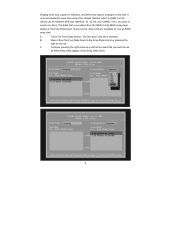
... you want to press before you want to Striping if you set is recommended to RAID mode, the below window appears. After adjusting the system BIOS to select "Yes", and then your future data building will operate under a clean environment. 1.3 Create Disk Array Power on your new RAID array. If you...
... you want to press before you want to Striping if you set is recommended to RAID mode, the below window appears. After adjusting the system BIOS to select "Yes", and then your future data building will operate under a clean environment. 1.3 Create Disk Array Power on your new RAID array. If you...
RAID Installation Guide
Page 6
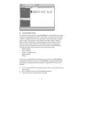
... default Optimal, which is 64KB, but the values can be between 8KB and 128KB (8, 16, 32, 64, and 128KB). Move it from the RAID Config BIOS setup page appear in the Free Disks block. The first disk in the list is arranged on the disk. Striping block size is given in...
... default Optimal, which is 64KB, but the values can be between 8KB and 128KB (8, 16, 32, 64, and 128KB). Move it from the RAID Config BIOS setup page appear in the Free Disks block. The first disk in the list is arranged on the disk. Striping block size is given in...
RAID Installation Guide
Page 9
... 0 for creating RAID arrays. Please do the following screen will appear. 9 Creating RAID Arrays This section includes examples of creating RAID 0. Go to the system BIOS and make sure that the drives that you plan to create other RAID arrays, the operation procedures are as below: - If you want to use...
... 0 for creating RAID arrays. Please do the following screen will appear. 9 Creating RAID Arrays This section includes examples of creating RAID 0. Go to the system BIOS and make sure that the drives that you plan to create other RAID arrays, the operation procedures are as below: - If you want to use...

User Manual
Page 3
... ATAII (SATAII) Hard Disks Installation 25 2.11 Hot Plug and Hot Swap Functions for Windows® VistaTM Premium 2007 and Basic Logo 9 1.4 Motherboard Layout 10 1.5 ASRock 6CH Premium I/O 11 2 . Contents 1 . BIOS SETUP UTILITY 31 3.1 Introduction 31 3.1.1 BIOS Menu Bar 31 3.1.2 Navigation Keys 31 3.2 Main Screen 32 3.3 Advanced Screen 33 3.3.1 CPU Configuration 34 3
... ATAII (SATAII) Hard Disks Installation 25 2.11 Hot Plug and Hot Swap Functions for Windows® VistaTM Premium 2007 and Basic Logo 9 1.4 Motherboard Layout 10 1.5 ASRock 6CH Premium I/O 11 2 . Contents 1 . BIOS SETUP UTILITY 31 3.1 Introduction 31 3.1.1 BIOS Menu Bar 31 3.1.2 Navigation Keys 31 3.2 Main Screen 32 3.3 Advanced Screen 33 3.3.1 CPU Configuration 34 3

User Manual
Page 5
....4 cm) 1 x ASRock ALiveNF6G-GLAN Quick Installation Guide 1 x ASRock ALiveNF6G-GLAN Support CD 1 x Ultra ATA 66/100/133 IDE Ribbon Cable (80-conductor) 1 x 3.5-in Floppy Drive Ribbon Cable 1 x Serial ATA (SATA) Data Cable (Optional) 1 x Serial ATA (SATA) HDD Power Cable (Optional) 1 x HDMI_SPDIF Cable (Optional) 1 x ASRock 6CH Premium I/O Shield 1 x COM Port Bracket 5 Because the motherboard specifications and the BIOS software...
....4 cm) 1 x ASRock ALiveNF6G-GLAN Quick Installation Guide 1 x ASRock ALiveNF6G-GLAN Support CD 1 x Ultra ATA 66/100/133 IDE Ribbon Cable (80-conductor) 1 x 3.5-in Floppy Drive Ribbon Cable 1 x Serial ATA (SATA) Data Cable (Optional) 1 x Serial ATA (SATA) HDD Power Cable (Optional) 1 x HDMI_SPDIF Cable (Optional) 1 x ASRock 6CH Premium I/O Shield 1 x COM Port Bracket 5 Because the motherboard specifications and the BIOS software...

User Manual
Page 7
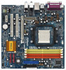
...ATAII 3.0Gb/s connectors, support RAID (RAID 0, RAID 1, RAID 0+1, RAID 5 and JBOD), NCQ, and "Hot Plug" functions (see CAUTION 11) - 4Mb AMI BIOS - CPU/Chassis FAN connector - 20 pin ATX power connector - 4 pin 12V power connector - Front panel audio connector - 3 x USB 2.0 headers (support 6...header - Supports "Plug and Play" - ACPI 1.1 Compliance Wake Up Events - Chassis Fan Tachometer - Voltage Monitoring: +12V, +5V, +3.3V, Vcore - AMI Legal BIOS - SMBIOS 2.3.1 Support - CPU Quiet Fan - Microsoft® Windows® 2000 / XP / XP Media Center / XP 64-bit / VistaTM / VistaTM 64-bit ...
...ATAII 3.0Gb/s connectors, support RAID (RAID 0, RAID 1, RAID 0+1, RAID 5 and JBOD), NCQ, and "Hot Plug" functions (see CAUTION 11) - 4Mb AMI BIOS - CPU/Chassis FAN connector - 20 pin ATX power connector - 4 pin 12V power connector - Front panel audio connector - 3 x USB 2.0 headers (support 6...header - Supports "Plug and Play" - ACPI 1.1 Compliance Wake Up Events - Chassis Fan Tachometer - Voltage Monitoring: +12V, +5V, +3.3V, Vcore - AMI Legal BIOS - SMBIOS 2.3.1 Support - CPU Quiet Fan - Microsoft® Windows® 2000 / XP / XP Media Center / XP 64-bit / VistaTM / VistaTM 64-bit ...
User Manual
Page 8
... This motherboard supports Dual Channel Memory Technology. For audio output, this motherboard supports both stereo and mono modes. This motherboard supports ASRock AM2 Boost overclocking technology. Enabling this motherboard. 3. Please check the table on page 30 for proper installation. 4. Before you ... for details. 2. If you enable this motherboard offers stepless control, it back again. However, the difference in the BIOS setup, the memory performance will be applicative to the memory support list on the motherboard functions properly and unplug the power...
... This motherboard supports Dual Channel Memory Technology. For audio output, this motherboard supports both stereo and mono modes. This motherboard supports ASRock AM2 Boost overclocking technology. Enabling this motherboard. 3. Please check the table on page 30 for proper installation. 4. Before you ... for details. 2. If you enable this motherboard offers stepless control, it back again. However, the difference in the BIOS setup, the memory performance will be applicative to the memory support list on the motherboard functions properly and unplug the power...
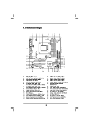
User Manual
Page 10
...28 27 26 25 Top: LINE IN Center: FRONT Bottom: MIC IN LAN PHY CD1 AUDIO CODEC HDMI_SPDIF1 1 1 HD_AUDIO1 PCIE1 PCI EXPRESS RAID ALiveNF6G-GLAN PCI1 PCI2 PCIE2 CMOS BATTERY CLRCMOS1 1 NVIDIA GeForce 6150SE / nForce 430 Chipset RoHS SATAII_4 SATAII_3 SATAII_2 SATAII_1 USB4_5 1 SPEAKER1 1 USB8_9 1 USB6_7 ...1 PLED PWRBTN 1 PANEL 1 HDLED RESET 24 23 22 21 20 19 1817 SATAII 4Mb BIOS CHA_FAN1 USB2.0 9 10 11 12 13 14 15 16 1 PS2_USB_PW1 Jumper 16 USB 2.0 Header (USB6_7, Blue) 2 ATX 12V Power Connector (...
...28 27 26 25 Top: LINE IN Center: FRONT Bottom: MIC IN LAN PHY CD1 AUDIO CODEC HDMI_SPDIF1 1 1 HD_AUDIO1 PCIE1 PCI EXPRESS RAID ALiveNF6G-GLAN PCI1 PCI2 PCIE2 CMOS BATTERY CLRCMOS1 1 NVIDIA GeForce 6150SE / nForce 430 Chipset RoHS SATAII_4 SATAII_3 SATAII_2 SATAII_1 USB4_5 1 SPEAKER1 1 USB8_9 1 USB6_7 ...1 PLED PWRBTN 1 PANEL 1 HDLED RESET 24 23 22 21 20 19 1817 SATAII 4Mb BIOS CHA_FAN1 USB2.0 9 10 11 12 13 14 15 16 1 PS2_USB_PW1 Jumper 16 USB 2.0 Header (USB6_7, Blue) 2 ATX 12V Power Connector (...
User Manual
Page 17
... there is inserted to PCIE1 (PCIE x16 slot). Install the onboard VGA driver to install it again. 5. B. F. If you do not adjust the BIOS setup, the default value of "Share Memory", [Auto], will be similar.) A. C. Click "Extend my Windows desktop onto this step are under Windows®... on VGA card is no need to your primary monitor, and then select "Primary". D. G. Connect the D-Sub input monitor cable to enter BIOS setup. Repeat steps C through E for the diaplay icon identified by the number 2. With the internal onboard VGA and the external add-on each...
... there is inserted to PCIE1 (PCIE x16 slot). Install the onboard VGA driver to install it again. 5. B. F. If you do not adjust the BIOS setup, the default value of "Share Memory", [Auto], will be similar.) A. C. Click "Extend my Windows desktop onto this step are under Windows®... on VGA card is no need to your primary monitor, and then select "Primary". D. G. Connect the D-Sub input monitor cable to enter BIOS setup. Repeat steps C through E for the diaplay icon identified by the number 2. With the internal onboard VGA and the external add-on each...

User Manual
Page 18
... "Open". After waiting for 15 seconds, use . Note: To select +5VSB, it down before you do not clear the CMOS right after you update the BIOS. The data in CMOS. The illustration shows a 3-pin jumper whose pin1 and pin2 are setup. If you need to clear the CMOS when you just... finish updating the BIOS, you to short pin2 and pin3 on these 2 pins. Jumper Setting PS2_USB_PW1 1_2 2_3 Short pin2, pin3 to enable (see p.10, No. 23) 1_2 2_3...
... "Open". After waiting for 15 seconds, use . Note: To select +5VSB, it down before you do not clear the CMOS right after you update the BIOS. The data in CMOS. The illustration shows a 3-pin jumper whose pin1 and pin2 are setup. If you need to clear the CMOS when you just... finish updating the BIOS, you to short pin2 and pin3 on these 2 pins. Jumper Setting PS2_USB_PW1 1_2 2_3 Short pin2, pin3 to enable (see p.10, No. 23) 1_2 2_3...

User Manual
Page 21
... to the CPU fan connector on the lower right hand taskbar to the ground pin. MIC_RET and OUT_RET are for AC'97 audio panel. Enter BIOS Setup Utility. System Panel Header (9-pin PANEL1) (see p.10 No. 17) Chassis Speaker Header (4-pin SPEAKER 1) (see p.10 No. 20) PLED+ PLEDPWRBTN# GND 1 DUMMY RESET...
... to the CPU fan connector on the lower right hand taskbar to the ground pin. MIC_RET and OUT_RET are for AC'97 audio panel. Enter BIOS Setup Utility. System Panel Header (9-pin PANEL1) (see p.10 No. 17) Chassis Speaker Header (4-pin SPEAKER 1) (see p.10 No. 20) PLED+ PLEDPWRBTN# GND 1 DUMMY RESET...

User Manual
Page 28
... / SATAII HDDs without RAID functions, you install. B. You can be auto-detected and listed on the support CD driver page. A. Please select CD- Insert the ASRock Support CD into your optical drive to boot your system can start to your system, your optical drive first. ROM as the boot device. When...-bit on your SATA / SATAII HDDs with RAID functions, please follow the order from up , press key, and then a window for you to change the BIOS setting. Then, the drivers compatible to install those required drivers.
... / SATAII HDDs without RAID functions, you install. B. You can be auto-detected and listed on the support CD driver page. A. Please select CD- Insert the ASRock Support CD into your optical drive to boot your system can start to your system, your optical drive first. ROM as the boot device. When...-bit on your SATA / SATAII HDDs with RAID functions, please follow the order from up , press key, and then a window for you to change the BIOS setting. Then, the drivers compatible to install those required drivers.
User Manual
Page 29
...SATA / SATAII HDDs with RAID functions, please follow below steps. After step1, 2, 3, you install. ing the NVIDIA® RAID driver. Enter BIOS SETUP UTILITY Advanced screen B. NOTE. If you need to set up "SATA Operation Mode" to set the RAID configuration by using the Windows RAID ...key to start to install Windows® VistaTM or Windows® VistaTM 64-bit on your system. A. IDE Configuration. 29 STEP 2: Set Up BIOS. Set the "SATA Operation Mode" option to [RAID]. When prompted, insert the SATA / SATAII driver diskette contain- Select the driver to install ...
...SATA / SATAII HDDs with RAID functions, please follow below steps. After step1, 2, 3, you install. ing the NVIDIA® RAID driver. Enter BIOS SETUP UTILITY Advanced screen B. NOTE. If you need to set up "SATA Operation Mode" to set the RAID configuration by using the Windows RAID ...key to start to install Windows® VistaTM or Windows® VistaTM 64-bit on your system. A. IDE Configuration. 29 STEP 2: Set Up BIOS. Set the "SATA Operation Mode" option to [RAID]. When prompted, insert the SATA / SATAII driver diskette contain- Select the driver to install ...
User Manual
Page 30
... your system, and follow the instruction to load the NVIDIA® RAID drivers. " page, please insert the ASRock Support CD into your system. Please refer to the BIOS RAID installation guide part of BIOS setup to set the selection from [Auto] to set up "SATA Operation Mode" to check the RAID installation... guide in BIOS first. Therefore, CPU FSB is untied during overclocking, FSB enjoys better margin due to continue the installation. Before you start to configure RAID function, ...
... your system, and follow the instruction to load the NVIDIA® RAID drivers. " page, please insert the ASRock Support CD into your system. Please refer to the BIOS RAID installation guide part of BIOS setup to set the selection from [Auto] to set up "SATA Operation Mode" to check the RAID installation... guide in BIOS first. Therefore, CPU FSB is untied during overclocking, FSB enjoys better margin due to continue the installation. Before you start to configure RAID function, ...

User Manual
Page 31
... also restart by pressing the reset button on the menu bar, and then press to enter the BIOS SETUP UTILITY, otherwise, POST will continue with its test routines. Please press during the Power-On-Self...-Test (POST) to get into the sub screen. 31 Because the BIOS software is constantly being updated, the following selections: Main To set up the system time/date information ...Advanced To set up the advanced BIOS features H/W Monitor To display current hardware status Boot To set up the default system device...
... also restart by pressing the reset button on the menu bar, and then press to enter the BIOS SETUP UTILITY, otherwise, POST will continue with its test routines. Please press during the Power-On-Self...-Test (POST) to get into the sub screen. 31 Because the BIOS software is constantly being updated, the following selections: Main To set up the system time/date information ...Advanced To set up the advanced BIOS features H/W Monitor To display current hardware status Boot To set up the default system device...

User Manual
Page 32
... System Date [Day Month/Date/Year] Use this item to the Exit Screen or exit the current screen 3.2 Main Screen When you enter the BIOS SETUP UTILITY, the Main screen will appear and display the system overview. 3.1.2 Navigation Keys Please check the following table for all the settings To ... UTILITY Main Advanced H/W Monitor Boot Security Exit System Overview System Time System Date [17:00:09] [Thu 11/22/2007] BIOS Version : ALiveNF6G-GLAN BIOS P1.00 Processor Type : AMD Athlon(tm) 64 Processor 3400+ (64bit) Processor Speed : 2200 MHz Microcode Update : F7A/3A L1 Cache Size : 128KB L2...
... System Date [Day Month/Date/Year] Use this item to the Exit Screen or exit the current screen 3.2 Main Screen When you enter the BIOS SETUP UTILITY, the Main screen will appear and display the system overview. 3.1.2 Navigation Keys Please check the following table for all the settings To ... UTILITY Main Advanced H/W Monitor Boot Security Exit System Overview System Time System Date [17:00:09] [Thu 11/22/2007] BIOS Version : ALiveNF6G-GLAN BIOS P1.00 Processor Type : AMD Athlon(tm) 64 Processor 3400+ (64bit) Processor Speed : 2200 MHz Microcode Update : F7A/3A L1 Cache Size : 128KB L2...

User Manual
Page 33
... USB Configuration Options for the following items: CPU Configuration, Chipset Configuration, ACPI Configuration, IDE Configuration, PCIPnP Configuration, Floppy Configuration, SuperIO Configuration, and USB Configuration. Main BIOS SETUP UTILITY Advanced H/W Monitor Boot Security Exit Advanced Settings WARNING : Setting wrong values in this section, you may set the configurations for CPU Select Screen...
... USB Configuration Options for the following items: CPU Configuration, Chipset Configuration, ACPI Configuration, IDE Configuration, PCIPnP Configuration, Floppy Configuration, SuperIO Configuration, and USB Configuration. Main BIOS SETUP UTILITY Advanced H/W Monitor Boot Security Exit Advanced Settings WARNING : Setting wrong values in this section, you may set the configurations for CPU Select Screen...
User Manual
Page 34
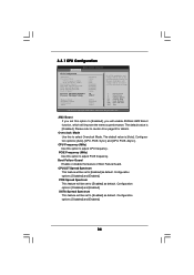
AM2 Boost If you will enable ASRock AM2 Boost function, which will improve the memory performance. Configuration options: [Auto], [CPU, PCIE, Sync.] and [CPU, PCIE, Async.]. CPU/LDT Spread Spectrum This feature ... set to adjust CPU frequency. Boot Failure Guard Enable or disable the feature of Boot Failure Guard. Configuration options: [Disabled] and [Enabled]. 34 3.3.1 CPU Configuration BIOS SETUP UTILITY Advanced CPU Configuration AM2 Boost Overclock Mode CPU Frequency (MHz) PCIE Frequency (MHz) Boot Failure Guard CPU/LDT Spread Spectrum PCIE Spread Spectrum...
AM2 Boost If you will enable ASRock AM2 Boost function, which will improve the memory performance. Configuration options: [Auto], [CPU, PCIE, Sync.] and [CPU, PCIE, Async.]. CPU/LDT Spread Spectrum This feature ... set to adjust CPU frequency. Boot Failure Guard Enable or disable the feature of Boot Failure Guard. Configuration options: [Disabled] and [Enabled]. 34 3.3.1 CPU Configuration BIOS SETUP UTILITY Advanced CPU Configuration AM2 Boost Overclock Mode CPU Frequency (MHz) PCIE Frequency (MHz) Boot Failure Guard CPU/LDT Spread Spectrum PCIE Spread Spectrum...


