
RAID Installation Guide
Page 2
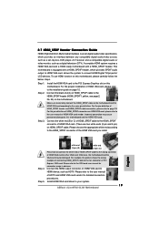
...-Plug any fault tolerance. Please refer to configure RAID. SATAII_2 (port 1.1) --> Means controller 1 's second port. For optimal performance, please install identical drives of the "User Manual" in our support CD or "Quick Installation Guide", you install. RAID 0 (Data Striping) RAID 0 is equipped with your motherboard provides in advance and follow the...
...-Plug any fault tolerance. Please refer to configure RAID. SATAII_2 (port 1.1) --> Means controller 1 's second port. For optimal performance, please install identical drives of the "User Manual" in our support CD or "Quick Installation Guide", you install. RAID 0 (Data Striping) RAID 0 is equipped with your motherboard provides in advance and follow the...

User Manual
Page 1
ALiveNF6G-GLAN User Manual Version 1.0 Published November 2007 Copyright©2007 ASRock INC. All rights reserved. 1
ALiveNF6G-GLAN User Manual Version 1.0 Published November 2007 Copyright©2007 ASRock INC. All rights reserved. 1

User Manual
Page 2
...any errors or omissions that may cause undesired operation. "Perchlorate Material-special handling may appear in this manual. With respect to the contents of this manual, ASRock does not provide warranty of any kind, either expressed or implied, including but not limited to ...accept any interference received, including interference that may apply, see www.dtsc.ca.gov/hazardouswaste/perchlorate" ASRock Website: http://www.asrock.com 2 Copyright Notice: No part of this manual may be liable for any indirect, special, incidental, or consequential damages (including damages for loss ...
...any errors or omissions that may cause undesired operation. "Perchlorate Material-special handling may appear in this manual. With respect to the contents of this manual, ASRock does not provide warranty of any kind, either expressed or implied, including but not limited to ...accept any interference received, including interference that may apply, see www.dtsc.ca.gov/hazardouswaste/perchlorate" ASRock Website: http://www.asrock.com 2 Copyright Notice: No part of this manual may be liable for any indirect, special, incidental, or consequential damages (including damages for loss ...

User Manual
Page 5
... and CPU support lists on ASRock website without notice. www.asrock.com/support/index.asp 1.1 Package Contents 1 x ASRock ALiveNF6G-GLAN Motherboard (Micro ATX Form Factor: 9.6-in x 9.6-in, 24.4 cm x 24.4 cm) 1 x ASRock ALiveNF6G-GLAN Quick Installation Guide 1 x ASRock ALiveNF6G-GLAN Support CD 1 x Ultra ...ASRock 6CH Premium I/O Shield 1 x COM Port Bracket 5 ASRock website http://www.asrock.com If you are using. Introduction Thank you for specific information about the model you require technical support related to the hardware installation. In case any modifications of this manual...
... and CPU support lists on ASRock website without notice. www.asrock.com/support/index.asp 1.1 Package Contents 1 x ASRock ALiveNF6G-GLAN Motherboard (Micro ATX Form Factor: 9.6-in x 9.6-in, 24.4 cm x 24.4 cm) 1 x ASRock ALiveNF6G-GLAN Quick Installation Guide 1 x ASRock ALiveNF6G-GLAN Support CD 1 x Ultra ...ASRock 6CH Premium I/O Shield 1 x COM Port Bracket 5 ASRock website http://www.asrock.com If you are using. Introduction Thank you for specific information about the model you require technical support related to the hardware installation. In case any modifications of this manual...

User Manual
Page 13
... And Lock To The Socket Corner The Socket Lever 2.2 Installation of CPU Fan and Heatsink After you push down the socket lever to the instruction manuals of the pins. Make sure that the CPU corner with the golden triangle matches the socket corner with each other. Position the CPU directly above...
... And Lock To The Socket Corner The Socket Lever 2.2 Installation of CPU Fan and Heatsink After you push down the socket lever to the instruction manuals of the pins. Make sure that the CPU corner with the golden triangle matches the socket corner with each other. Position the CPU directly above...

User Manual
Page 20
... P+4 P-4 USB_PWR IRTX +5VSB DUMMY 1 GND IRRX CD1 This header supports an optional wireless transmitting and receiving infrared module. Please follow the instruction in our manual and chassis manual to MIC2_L. Connect Audio_R (RIN) to OUT2_R and Audio_L (LIN) to function correctly. This connector allows you use AC'97 audio panel, please install...
... P+4 P-4 USB_PWR IRTX +5VSB DUMMY 1 GND IRRX CD1 This header supports an optional wireless transmitting and receiving infrared module. Please follow the instruction in our manual and chassis manual to MIC2_L. Connect Audio_R (RIN) to OUT2_R and Audio_L (LIN) to function correctly. This connector allows you use AC'97 audio panel, please install...
User Manual
Page 23
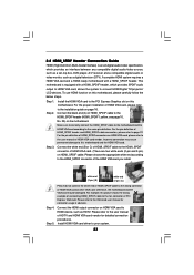
...card. For the pin definition of HDMI VGA card or other VGA card. Incorrect connection may be damaged. Please refer to the user manual of HDMI_SPDIF cable to the installation guide on the motherboard. Install HDMI VGA card driver to the same pin definition. For the proper ... VGA card vendor. Connect the HDMI output connector on HDMI_SPDIF cable. Connect the white end (B or C) of HDMI_SPDIF cable to the VGA card user manual for detailed connection procedures. Step 3. Connect the black end (A) of HDTV and HDMI VGA card vendor for connector usage in advance. Step 5. 2.8 ...
...card. For the pin definition of HDMI VGA card or other VGA card. Incorrect connection may be damaged. Please refer to the user manual of HDMI_SPDIF cable to the installation guide on the motherboard. Install HDMI VGA card driver to the same pin definition. For the proper ... VGA card vendor. Connect the HDMI output connector on HDMI_SPDIF cable. Connect the white end (B or C) of HDMI_SPDIF cable to the VGA card user manual for detailed connection procedures. Step 3. Connect the black end (A) of HDTV and HDMI VGA card vendor for connector usage in advance. Step 5. 2.8 ...

User Manual
Page 26
...interfaces, the IDE 1x4-pin conventional power connector interface is indicated in the product spec on our support website: www.asrock.com 4. The SATA / SATAII HDD, which are from the motherboard gift box pack. SATA power cable SATA 7-pin... B. Before you process the Hot Plug: 1. Please make sure the SATA / SATAII driver is available on our website: www.asrock.com 2. Please read below instructions step by the chipset because of its limitation, the SATA / SATAII Hot Plug support information of... SATA / SATAII HDD can support Hot Plug function from your dealer or HDD user manual.
...interfaces, the IDE 1x4-pin conventional power connector interface is indicated in the product spec on our support website: www.asrock.com 4. The SATA / SATAII HDD, which are from the motherboard gift box pack. SATA power cable SATA 7-pin... B. Before you process the Hot Plug: 1. Please make sure the SATA / SATAII driver is available on our website: www.asrock.com 2. Please read below instructions step by the chipset because of its limitation, the SATA / SATAII Hot Plug support information of... SATA / SATAII HDD can support Hot Plug function from your dealer or HDD user manual.
User Manual
Page 34
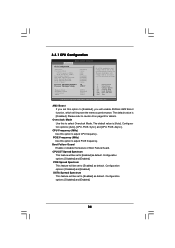
If Manual, multiplier and voltage will be set based on page 8 for details. AM2 Boost If you set this option to adjust CPU frequency. Please refer to ...: [Disabled] and [Enabled]. Configuration options: [Disabled] and [Enabled]. 34 The default value is [Auto]. CPU Frequency (MHz) Use this option to [Enabled], you will enable ASRock AM2 Boost function, which will improve the memory performance. PCIE Spread Spectrum This feature will be set to [Enabled] as default. Overclock Mode Use this...
If Manual, multiplier and voltage will be set based on page 8 for details. AM2 Boost If you set this option to adjust CPU frequency. Please refer to ...: [Disabled] and [Enabled]. Configuration options: [Disabled] and [Enabled]. 34 The default value is [Auto]. CPU Frequency (MHz) Use this option to [Enabled], you will enable ASRock AM2 Boost function, which will improve the memory performance. PCIE Spread Spectrum This feature will be set to [Enabled] as default. Overclock Mode Use this...
User Manual
Page 35
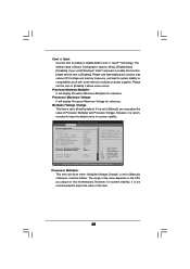
... or compatibility issue with some memory modules or power supplies. Configuration options: [Auto], [Enabled] and [Disabled]. If Manual, multiplier and voltage will be set to [Enabled]. However, for system stability. Please note that enabling this function may...] [Enabled] [Enabled] [Enabled] [Auto] Processor Maximum Multiplier Processor Maximum Voltage Multiplier/Voltage Change Processor Multiplier Processor Voltage x11 1.550 V [Manual] [x8] [1.500V] If AUTO, multiplier and voltage will be left at the rated frequency/voltage. Processor Multiplier This item will display Processor...
... or compatibility issue with some memory modules or power supplies. Configuration options: [Auto], [Enabled] and [Disabled]. If Manual, multiplier and voltage will be set to [Enabled]. However, for system stability. Please note that enabling this function may...] [Enabled] [Enabled] [Enabled] [Auto] Processor Maximum Multiplier Processor Maximum Voltage Multiplier/Voltage Change Processor Multiplier Processor Voltage x11 1.550 V [Manual] [x8] [1.500V] If AUTO, multiplier and voltage will be left at the rated frequency/voltage. Processor Multiplier This item will display Processor...

User Manual
Page 36
... code using [Auto]. The default value is [Auto]. Configuration options: [Auto], [3CLK], [4CLK], [5CLK] and [6CLK]. The default value is [Auto]. TRTP Use this to [Manual]; Configuration options: [Auto], [3CLK], [4CLK], [5CLK] and [6CLK]. otherwise, it is set to adjust TRAS values. The default value is [Disabled]. The range of this...
... code using [Auto]. The default value is [Auto]. Configuration options: [Auto], [3CLK], [4CLK], [5CLK] and [6CLK]. The default value is [Auto]. TRTP Use this to [Manual]; Configuration options: [Auto], [3CLK], [4CLK], [5CLK] and [6CLK]. otherwise, it is set to adjust TRAS values. The default value is [Disabled]. The range of this...

Quick Installation Guide
Page 4
... this manual will be updated, the content of this motherboard, please visit our website for specific information about the model you for purchasing ASRock ALiveNF6G-GLAN motherboard, a reliable motherboard produced under ASRock's consistently stringent quality control. www.asrock.com/support/index.asp 1.1 Package Contents 1 x ASRock ALiveNF6G-GLAN Motherboard (Micro ATX Form Factor: 9.6-in x 9.6-in, 24.4 cm x 24.4 cm) 1 x ASRock ALiveNF6G-GLAN Quick...
... this manual will be updated, the content of this motherboard, please visit our website for specific information about the model you for purchasing ASRock ALiveNF6G-GLAN motherboard, a reliable motherboard produced under ASRock's consistently stringent quality control. www.asrock.com/support/index.asp 1.1 Package Contents 1 x ASRock ALiveNF6G-GLAN Motherboard (Micro ATX Form Factor: 9.6-in x 9.6-in, 24.4 cm x 24.4 cm) 1 x ASRock ALiveNF6G-GLAN Quick...

Quick Installation Guide
Page 9
...a grounded antstatic pad or in place, press it firmly on the socket while you push down the socket lever to the instruction manuals of the following precautions before you install motherboard components or change any component. Step 2. When the CPU is locked. The lever clicks...socket corner with the component. 5. Position the CPU directly above the socket such that it fits in one correct orientation. English 9 ASRock ALiveNF6G-GLAN Motherboard When placing screws into the socket to the chassis, please do not over-tighten the screws! DO NOT force the CPU into...
...a grounded antstatic pad or in place, press it firmly on the socket while you push down the socket lever to the instruction manuals of the following precautions before you install motherboard components or change any component. Step 2. When the CPU is locked. The lever clicks...socket corner with the component. 5. Position the CPU directly above the socket such that it fits in one correct orientation. English 9 ASRock ALiveNF6G-GLAN Motherboard When placing screws into the socket to the chassis, please do not over-tighten the screws! DO NOT force the CPU into...

Quick Installation Guide
Page 16
This connector allows you use AC'97 audio panel, please install it to MIC2_L. Please follow the instruction in our manual and chassis manual to receive stereo audio input from sound sources such as below: A. Connect Mic_IN (MIC) to the front panel audio header as ... of audio devices. 1. If you CD1 to install your system. 2. Connect Audio_R (RIN) to OUT2_R and Audio_L (LIN) to OUT2_L. 16 ASRock ALiveNF6G-GLAN Motherboard English High Definition Audio supports Jack Sensing, but the panel wire on this motherboard. Each USB 2.0 header can support two USB 2.0 ports. ...
This connector allows you use AC'97 audio panel, please install it to MIC2_L. Please follow the instruction in our manual and chassis manual to receive stereo audio input from sound sources such as below: A. Connect Mic_IN (MIC) to the front panel audio header as ... of audio devices. 1. If you CD1 to install your system. 2. Connect Audio_R (RIN) to OUT2_R and Audio_L (LIN) to OUT2_L. 16 ASRock ALiveNF6G-GLAN Motherboard English High Definition Audio supports Jack Sensing, but the panel wire on this motherboard. Each USB 2.0 header can support two USB 2.0 ports. ...
Quick Installation Guide
Page 19
...Step 1. For example, this motherboard and the HDMI VGA card. Please refer to your system. 19 ASRock ALiveNF6G-GLAN Motherboard Connect the HDMI output connector on HDMI VGA card, please refer to the user manual of PCI Express VGA card. Please choose the appropriate white end according to the HDMI_SPDIF connector of ...the white end of HDMI_SPDIF cable to the wrong connector of the HDMI VGA card you install. Please refer to the user manual of HDMI_SPDIF header and HDMI_SPDIF cable connectors, please refer to page 18. Install HDMI VGA card driver to the VGA card user...
...Step 1. For example, this motherboard and the HDMI VGA card. Please refer to your system. 19 ASRock ALiveNF6G-GLAN Motherboard Connect the HDMI output connector on HDMI VGA card, please refer to the user manual of PCI Express VGA card. Please choose the appropriate white end according to the HDMI_SPDIF connector of ...the white end of HDMI_SPDIF cable to the wrong connector of the HDMI VGA card you install. Please refer to the user manual of HDMI_SPDIF header and HDMI_SPDIF cable connectors, please refer to page 18. Install HDMI VGA card driver to the VGA card user...

Quick Installation Guide
Page 25
..." is designed to enter BIOS Setup utility; It will enhance motherboard features. The BIOS Setup program is enabled in the Support CD to the User Manual (PDF file) contained in the Support CD. 4. To begin using the Support CD, insert the CD into your computer. 3. When you to scroll through its... pressing the reset button on the motherboard stores BIOS Setup Utility. For the detailed information about BIOS Setup, please refer to display the menus. 25 ASRock ALiveNF6G-GLAN Motherboard English
..." is designed to enter BIOS Setup utility; It will enhance motherboard features. The BIOS Setup program is enabled in the Support CD to the User Manual (PDF file) contained in the Support CD. 4. To begin using the Support CD, insert the CD into your computer. 3. When you to scroll through its... pressing the reset button on the motherboard stores BIOS Setup Utility. For the detailed information about BIOS Setup, please refer to display the menus. 25 ASRock ALiveNF6G-GLAN Motherboard English
