User Manual
Page 5
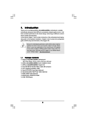
... notice. Introduction Thank you for purchasing ASRock ALiveNF5-eSATA2+ motherboard, a reliable motherboard produced under ASRock's consistently stringent quality control. In this manual will be subject to the hardware installation. ASRock website http://www.asrock.com 1.1 Package Contents 1 x ASRock ALiveNF5-eSATA2+ Motherboard (ATX Form Factor: 12.0-in x 8.0-in, 30.5 cm x 20.3 cm) 1 x ASRock ALiveNF5-eSATA2+ Quick Installation Guide 1 x ASRock ALiveNF5-eSATA2+ Support CD 1 x Ultra ATA 66...
... notice. Introduction Thank you for purchasing ASRock ALiveNF5-eSATA2+ motherboard, a reliable motherboard produced under ASRock's consistently stringent quality control. In this manual will be subject to the hardware installation. ASRock website http://www.asrock.com 1.1 Package Contents 1 x ASRock ALiveNF5-eSATA2+ Motherboard (ATX Form Factor: 12.0-in x 8.0-in, 30.5 cm x 20.3 cm) 1 x ASRock ALiveNF5-eSATA2+ Quick Installation Guide 1 x ASRock ALiveNF5-eSATA2+ Support CD 1 x Ultra ATA 66...

Quick Installation Guide
Page 1
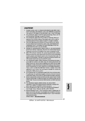
...Material-special handling may apply, see www.dtsc.ca.gov/hazardouswaste/perchlorate" ASRock Website: http://www.asrock.com Published March 2007 Copyright©2007 ASRock INC. ASRock assumes no event shall ASRock, its directors, officers, employees, or agents be liable for any indirect...interference, and (2) this device must accept any errors or omissions that may cause undesired operation. All rights reserved. 1 ASRock ALiveNF5-eSATA2+ Motherboard English CALIFORNIA, USA ONLY The Lithium battery adopted on this motherboard contains Perchlorate, a toxic substance controlled in Perchlorate ...
...Material-special handling may apply, see www.dtsc.ca.gov/hazardouswaste/perchlorate" ASRock Website: http://www.asrock.com Published March 2007 Copyright©2007 ASRock INC. ASRock assumes no event shall ASRock, its directors, officers, employees, or agents be liable for any indirect...interference, and (2) this device must accept any errors or omissions that may cause undesired operation. All rights reserved. 1 ASRock ALiveNF5-eSATA2+ Motherboard English CALIFORNIA, USA ONLY The Lithium battery adopted on this motherboard contains Perchlorate, a toxic substance controlled in Perchlorate ...
Quick Installation Guide
Page 2
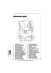
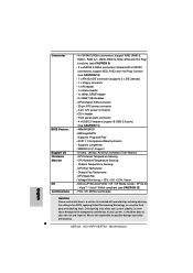
... Connector (ATXPWR1) 16 USB 2.0 Header (USB4_5, Blue) 36 eSATAII Connector (eSATAII_TOP) 17 USB 2.0 Header (USB2_3, Blue) 37 eSATAII Connector (eSATAII_BOTTOM) 18 Chassis Fan Connector (CHA_FAN1) 2 ASRock ALiveNF5-eSATA2+ Motherboard Yellow) 25 Front Panel Audio Header (HD_AUDIO1) 7 2 x 240-pin DDRII DIMM Slots 26 PCI Slots (PCI1- 3) (Dual Channel B: DDRII_3, DDRII_4;
... Connector (ATXPWR1) 16 USB 2.0 Header (USB4_5, Blue) 36 eSATAII Connector (eSATAII_TOP) 17 USB 2.0 Header (USB2_3, Blue) 37 eSATAII Connector (eSATAII_BOTTOM) 18 Chassis Fan Connector (CHA_FAN1) 2 ASRock ALiveNF5-eSATA2+ Motherboard Yellow) 25 Front Panel Audio Header (HD_AUDIO1) 7 2 x 240-pin DDRII DIMM Slots 26 PCI Slots (PCI1- 3) (Dual Channel B: DDRII_3, DDRII_4;
Quick Installation Guide
Page 3
...(No. 4) (No. 5) 2 V -- -- 4 V V -- 6 V V V 8 V V V Side Speaker (No. 3) ---V * To enable Multi-Streaming function, you use. Free Bundle ASRock provides you will find "Mixer" tool on your system. Please select "Mixer ToolBox" , click "Enable playback multi-streaming", and click "ok". After restarting your computer...in accordance with one USB+1394 bracket, which can support 2 additional USB 2.0 ports and 1 IEEE 1394 port. 3 ASRock ALiveNF5-eSATA2+ Motherboard English Choose "2CH", "4CH", "6CH", or "8CH" and then you use 2-channel speaker, please connect the speaker's...
...(No. 4) (No. 5) 2 V -- -- 4 V V -- 6 V V V 8 V V V Side Speaker (No. 3) ---V * To enable Multi-Streaming function, you use. Free Bundle ASRock provides you will find "Mixer" tool on your system. Please select "Mixer ToolBox" , click "Enable playback multi-streaming", and click "ok". After restarting your computer...in accordance with one USB+1394 bracket, which can support 2 additional USB 2.0 ports and 1 IEEE 1394 port. 3 ASRock ALiveNF5-eSATA2+ Motherboard English Choose "2CH", "4CH", "6CH", or "8CH" and then you use 2-channel speaker, please connect the speaker's...
Quick Installation Guide
Page 4
... case any modifications of this manual occur, the updated version will be available on ASRock website as well. ASRock website http://www.asrock.com 1.1 Package Contents 1 x ASRock ALiveNF5-eSATA2+ Motherboard (ATX Form Factor: 12.0-in x 8.0-in, 30.5 cm x 20.3 cm) 1 x ASRock ALiveNF5-eSATA2+ Quick Installation Guide 1 x ASRock ALiveNF5-eSATA2+ Support CD 1 x Ultra ATA 66/100/133 IDE Ribbon Cable (80-conductor) 1 x 3.5-in...
... case any modifications of this manual occur, the updated version will be available on ASRock website as well. ASRock website http://www.asrock.com 1.1 Package Contents 1 x ASRock ALiveNF5-eSATA2+ Motherboard (ATX Form Factor: 12.0-in x 8.0-in, 30.5 cm x 20.3 cm) 1 x ASRock ALiveNF5-eSATA2+ Quick Installation Guide 1 x ASRock ALiveNF5-eSATA2+ Support CD 1 x Ultra ATA 66/100/133 IDE Ribbon Cable (80-conductor) 1 x 3.5-in...
Quick Installation Guide
Page 5
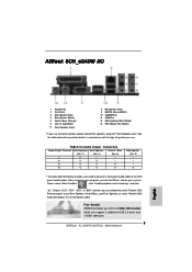
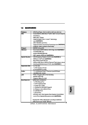
...64X2 / 64 and Sempron processors - Supports Untied Overclocking Technology (see CAUTION 6) - ASRock U-COP (see CAUTION 2) - FSB 1000 MHz (2.0 GT/s) - Supports Hyper-Transport Technology - ASRock AM2 Boost: ASRock Patented Technology to boost memory performance up to -Use USB 2.0 Ports - 2 x...CAUTION 8) Free Bundle: USB+1394 bracket, providing 2 additional USB 2.0 ports and 1 IEEE 1394 port 5 ASRock ALiveNF5-eSATA2+ Motherboard English Dual Channel DDRII Memory Technology (see CAUTION 1) - Support DDRII800/667/533 - Boot Failure Guard (B.F.G.) - Realtek RTL8111B - Supports...
...64X2 / 64 and Sempron processors - Supports Untied Overclocking Technology (see CAUTION 6) - ASRock U-COP (see CAUTION 2) - FSB 1000 MHz (2.0 GT/s) - Supports Hyper-Transport Technology - ASRock AM2 Boost: ASRock Patented Technology to boost memory performance up to -Use USB 2.0 Ports - 2 x...CAUTION 8) Free Bundle: USB+1394 bracket, providing 2 additional USB 2.0 ports and 1 IEEE 1394 port 5 ASRock ALiveNF5-eSATA2+ Motherboard English Dual Channel DDRII Memory Technology (see CAUTION 1) - Support DDRII800/667/533 - Boot Failure Guard (B.F.G.) - Realtek RTL8111B - Supports...
Quick Installation Guide
Page 6
... damage to the components and devices of your own risk and expense. CPU Quiet Fan - We are not responsible for possible damage caused by overclocking. 6 ASRock ALiveNF5-eSATA2+ Motherboard CPU Ambient Temperature Sensing - Drivers, Utilities, AntiVirus Software (Trial Version) - CPU/Chassis FAN connector - 20 pin ATX power connector - 4 pin 12V power connector - Supports...
... damage to the components and devices of your own risk and expense. CPU Quiet Fan - We are not responsible for possible damage caused by overclocking. 6 ASRock ALiveNF5-eSATA2+ Motherboard CPU Ambient Temperature Sensing - Drivers, Utilities, AntiVirus Software (Trial Version) - CPU/Chassis FAN connector - 20 pin ATX power connector - 4 pin 12V power connector - Supports...
Quick Installation Guide
Page 7
...Dual Channel Memory Technology. Although this function in the BIOS setup, the memory performance will automatically shutdown. This motherboard supports ASRock AM2 Boost overclocking technology. If your system is unstable after AM2 Boost function is enabled, it is not recommended to ... recommended to read "eSATAII Interface Introduction" on page 54 of "User Manual" in the future. If you adopt. ASRock website http://www.asrock.com 7 ASRock ALiveNF5-eSATA2+ Motherboard English See APPENDIX on page 22 for details. 3. For Windows® XP 64-bit and Windows® VistaTM...
...Dual Channel Memory Technology. Although this function in the BIOS setup, the memory performance will automatically shutdown. This motherboard supports ASRock AM2 Boost overclocking technology. If your system is unstable after AM2 Boost function is enabled, it is not recommended to ... recommended to read "eSATAII Interface Introduction" on page 54 of "User Manual" in the future. If you adopt. ASRock website http://www.asrock.com 7 ASRock ALiveNF5-eSATA2+ Motherboard English See APPENDIX on page 22 for details. 3. For Windows® XP 64-bit and Windows® VistaTM...

Quick Installation Guide
Page 8
English 8 ASRock ALiveNF5-eSATA2+ Motherboard 1.3 Minimum Hardware Requirement Table for Windows® VistaTM Premium 2007 and Basic Logo For system integrators and users who purchase this motherboard and plan ...
English 8 ASRock ALiveNF5-eSATA2+ Motherboard 1.3 Minimum Hardware Requirement Table for Windows® VistaTM Premium 2007 and Basic Logo For system integrators and users who purchase this motherboard and plan ...

Quick Installation Guide
Page 9
.... Whenever you handle components. 3. Also remember to ensure that comes with the component. 5. Hold components by the edges and do so may damage the motherboard. 9 ASRock ALiveNF5-eSATA2+ Motherboard English Pre-installation Precautions Take note of your motherboard directly on a grounded antistatic pad or in , 30.5 cm x 20.3 cm) motherboard. Installation This is...
.... Whenever you handle components. 3. Also remember to ensure that comes with the component. 5. Hold components by the edges and do so may damage the motherboard. 9 ASRock ALiveNF5-eSATA2+ Motherboard English Pre-installation Precautions Take note of your motherboard directly on a grounded antistatic pad or in , 30.5 cm x 20.3 cm) motherboard. Installation This is...
Quick Installation Guide
Page 10
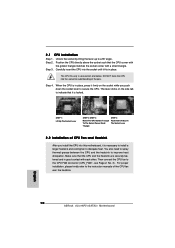
... Step 1. Step 2. Step 3. Step 4. When the CPU is necessary to install a larger heatsink and cooling fan to the instruction manuals of the pins. English 10 ASRock ALiveNF5-eSATA2+ Motherboard DO NOT force the CPU into the socket to secure the CPU. Lever 90° Up CPU Golden Triangle STEP 1: Lift Up The Socket...
... Step 1. Step 2. Step 3. Step 4. When the CPU is necessary to install a larger heatsink and cooling fan to the instruction manuals of the pins. English 10 ASRock ALiveNF5-eSATA2+ Motherboard DO NOT force the CPU into the socket to secure the CPU. Lever 90° Up CPU Golden Triangle STEP 1: Lift Up The Socket...
Quick Installation Guide
Page 11
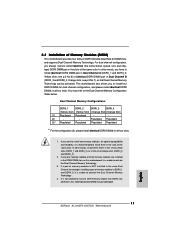
... of Memory Modules (DIMM) This motherboard provides four 240-pin DDRII (Double Data Rate II) DIMM slots, and supports Dual Channel Memory Technology. English 11 ASRock ALiveNF5-eSATA2+ Motherboard see p.2 No.7), so that Dual Channel Memory Technology can be damaged. In other words, install them in Dual Channel B (DDRII_3 and DDRII_4; Orange slots...
... of Memory Modules (DIMM) This motherboard provides four 240-pin DDRII (Double Data Rate II) DIMM slots, and supports Dual Channel Memory Technology. English 11 ASRock ALiveNF5-eSATA2+ Motherboard see p.2 No.7), so that Dual Channel Memory Technology can be damaged. In other words, install them in Dual Channel B (DDRII_3 and DDRII_4; Orange slots...

Quick Installation Guide
Page 12
... the slot at both ends fully snap back in one correct orientation. The DIMM only fits in place and the DIMM is properly seated. 12 ASRock ALiveNF5-eSATA2+ Motherboard English Align a DIMM on the slot such that the notch on the DIMM matches the break on the slot. Step 3. Installing a DIMM Please make...
... the slot at both ends fully snap back in one correct orientation. The DIMM only fits in place and the DIMM is properly seated. 12 ASRock ALiveNF5-eSATA2+ Motherboard English Align a DIMM on the slot such that the notch on the DIMM matches the break on the slot. Step 3. Installing a DIMM Please make...
Quick Installation Guide
Page 13
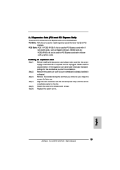
... hardware settings for PCI Express cards with screws. Step 5. Keep the screws for later use . Fasten the card to use . Replace the system cover. 13 ASRock ALiveNF5-eSATA2+ Motherboard English Align the card connector with x1 lane width cards, such as Gigabit LAN card, SATA2 card, etc. Installing an expansion card Step 1. Step...
... hardware settings for PCI Express cards with screws. Step 5. Keep the screws for later use . Fasten the card to use . Replace the system cover. 13 ASRock ALiveNF5-eSATA2+ Motherboard English Align the card connector with x1 lane width cards, such as Gigabit LAN card, SATA2 card, etc. Installing an expansion card Step 1. Step...

Quick Installation Guide
Page 14
...-CMOS action. To clear and reset the system parameters to enable (see p.2, No. 9) Default Clear CMOS Note: CLRCMOS1 allows you update the BIOS. English 14 ASRock ALiveNF5-eSATA2+ Motherboard If no jumper cap is placed on pins, the jumper is "Open". After waiting for 15 seconds, use a jumper cap to clear the data...
...-CMOS action. To clear and reset the system parameters to enable (see p.2, No. 9) Default Clear CMOS Note: CLRCMOS1 allows you update the BIOS. English 14 ASRock ALiveNF5-eSATA2+ Motherboard If no jumper cap is placed on pins, the jumper is "Open". After waiting for 15 seconds, use a jumper cap to clear the data...
Quick Installation Guide
Page 15
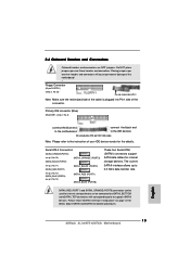
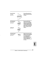
The current SATAII interface allows up to support eSATAII devices. English 15 ASRock ALiveNF5-eSATA2+ Motherboard Placing jumper caps over these headers and connectors. Please read "eSATAII Interface Introduction" on page 22 for internal storage devices. Serial ATA II Connectors (...
The current SATAII interface allows up to support eSATAII devices. English 15 ASRock ALiveNF5-eSATA2+ Motherboard Placing jumper caps over these headers and connectors. Please read "eSATAII Interface Introduction" on page 22 for internal storage devices. Serial ATA II Connectors (...
Quick Installation Guide
Page 16
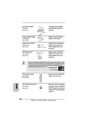
... 2.0 ports on the I/O panel, there are four USB 2.0 headers on this motherboard. USB 2.0 Headers (9-pin USB8_9) (see p.2 No. 14) (9-pin USB6_7) (see p.2 No. 16) 16 ASRock ALiveNF5-eSATA2+ Motherboard Then connect the white end of SATA power cable to the power connector of the SATA data cable can be connected to the power...
... 2.0 ports on the I/O panel, there are four USB 2.0 headers on this motherboard. USB 2.0 Headers (9-pin USB8_9) (see p.2 No. 14) (9-pin USB6_7) (see p.2 No. 16) 16 ASRock ALiveNF5-eSATA2+ Motherboard Then connect the white end of SATA power cable to the power connector of the SATA data cable can be connected to the power...
Quick Installation Guide
Page 17
... from sound sources such as below: A. Click "Audio I/O", select "Connector Settings" , choose "Disable front panel jack detection", and save the change by clicking "OK". 17 ASRock ALiveNF5-eSATA2+ Motherboard English Enter BIOS Setup Utility. F. Connect Audio_R (RIN) to OUT2_R and Audio_L (LIN) to install your system. 2. D. High Definition Audio supports Jack Sensing, but...
... from sound sources such as below: A. Click "Audio I/O", select "Connector Settings" , choose "Disable front panel jack detection", and save the change by clicking "OK". 17 ASRock ALiveNF5-eSATA2+ Motherboard English Enter BIOS Setup Utility. F. Connect Audio_R (RIN) to OUT2_R and Audio_L (LIN) to install your system. 2. D. High Definition Audio supports Jack Sensing, but...
Quick Installation Guide
Page 18
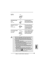
... p.2, No. 3) 1 2 3 4 Please connect the CPU fan cable to this connector and match the black wire to do so will cause power up failure. English 18 ASRock ALiveNF5-eSATA2+ Motherboard Though this connector. Failing to the ground pin. Please connect a chassis fan cable to this connector and match the black wire to Pin 1-3. If...
... p.2, No. 3) 1 2 3 4 Please connect the CPU fan cable to this connector and match the black wire to do so will cause power up failure. English 18 ASRock ALiveNF5-eSATA2+ Motherboard Though this connector. Failing to the ground pin. Please connect a chassis fan cable to this connector and match the black wire to Pin 1-3. If...
Quick Installation Guide
Page 19
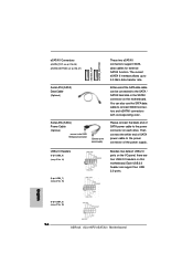
... GAME1) (see p.2, No. 24) Connect a Game cable to this header. Each IEEE 1394 header can support one back panel IEEE 1394 header (BACK_1394). English 19 ASRock ALiveNF5-eSATA2+ Motherboard HDMI_SPDIF Header HDMI_SPDIF header, providing (3-pin HDMI_SPDIF1) SPDIF audio output to HDMI VGA i (see p.2, No. 29) There are two IEEE 1394 headers on this...
... GAME1) (see p.2, No. 24) Connect a Game cable to this header. Each IEEE 1394 header can support one back panel IEEE 1394 header (BACK_1394). English 19 ASRock ALiveNF5-eSATA2+ Motherboard HDMI_SPDIF Header HDMI_SPDIF header, providing (3-pin HDMI_SPDIF1) SPDIF audio output to HDMI VGA i (see p.2, No. 29) There are two IEEE 1394 headers on this...


