
User Manual
Page 4
3.3.7 Super IO Configuration 39 3.3.8 USB Configuration 40 3.4 Hardware Health Event Monitoring Screen 41 3.5 Boot Screen 42 3.5.1 Boot Settings Configuration 42 3.6 Security Screen 43 3.7 Exit Screen 44 4 . Software Support 45 4.1 Install Operating System 45 4.2 Support CD Information 45 4.2.1 Running Support CD 45 4.2.2 Drivers Menu 45 4.2.3 Utilities Menu 45 4.2.4 Contact Information 45 APPENDIX: AMD's Cool 'n' QuietTM Technology ...... 46 4
3.3.7 Super IO Configuration 39 3.3.8 USB Configuration 40 3.4 Hardware Health Event Monitoring Screen 41 3.5 Boot Screen 42 3.5.1 Boot Settings Configuration 42 3.6 Security Screen 43 3.7 Exit Screen 44 4 . Software Support 45 4.1 Install Operating System 45 4.2 Support CD Information 45 4.2.1 Running Support CD 45 4.2.2 Drivers Menu 45 4.2.3 Utilities Menu 45 4.2.4 Contact Information 45 APPENDIX: AMD's Cool 'n' QuietTM Technology ...... 46 4
User Manual
Page 5
...://www.asrock.com 1.1 Package Contents 1 x ASRock ALiveNF4G-DVI Motherboard (Micro ATX Form Factor: 9.6-in x 9.6-in, 24.4 cm x 24.4 cm) 1 x ASRock ALiveNF4G-DVI Quick Installation Guide 1 x ASRock ALiveNF4G-DVI Support CD 1 x Ultra ATA 66/100/133 IDE Ribbon Cable (80-conductor) 1 x 3.5-in Floppy Drive Ribbon Cable 1 x Serial ATA (SATA) Data Cable (Optional) 1 x Serial ATA (SATA) HDD Power Cable (Optional) 1 x ASRock DVI I/O Shield 1 x USB+COM...
...://www.asrock.com 1.1 Package Contents 1 x ASRock ALiveNF4G-DVI Motherboard (Micro ATX Form Factor: 9.6-in x 9.6-in, 24.4 cm x 24.4 cm) 1 x ASRock ALiveNF4G-DVI Quick Installation Guide 1 x ASRock ALiveNF4G-DVI Support CD 1 x Ultra ATA 66/100/133 IDE Ribbon Cable (80-conductor) 1 x 3.5-in Floppy Drive Ribbon Cable 1 x Serial ATA (SATA) Data Cable (Optional) 1 x Serial ATA (SATA) HDD Power Cable (Optional) 1 x ASRock DVI I/O Shield 1 x USB+COM...

User Manual
Page 7
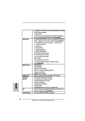
...x Floppy connector - 1 x IR header - 1 x Game header - 1 x COM port header - 1 x HDMI_SPDIF header - Front panel audio connector - 3 x USB 2.0 headers (support 6 USB 2.0 ports) (see CAUTION 9) - SMBIOS 2.3.1 Support - CPU Ambient Temperature Sensing - CPU/Chassis FAN connector - 20 pin ATX power connector - 4 pin 12V power connector...Internal Temperature Sensing - Connector BIOS Feature Support CD Hardware Monitor OS Certifications - 4 x Ready-to-Use USB 2.0 Ports (including 2 ports on bundled USB+COM port bracket) - 1 x RJ-45 Port - CPU Quiet Fan - AMI Legal BIOS - ...
...x Floppy connector - 1 x IR header - 1 x Game header - 1 x COM port header - 1 x HDMI_SPDIF header - Front panel audio connector - 3 x USB 2.0 headers (support 6 USB 2.0 ports) (see CAUTION 9) - SMBIOS 2.3.1 Support - CPU Ambient Temperature Sensing - CPU/Chassis FAN connector - 20 pin ATX power connector - 4 pin 12V power connector...Internal Temperature Sensing - Connector BIOS Feature Support CD Hardware Monitor OS Certifications - 4 x Ready-to-Use USB 2.0 Ports (including 2 ports on bundled USB+COM port bracket) - 1 x RJ-45 Port - CPU Quiet Fan - AMI Legal BIOS - ...

User Manual
Page 8
... the PC system. 6. Before installing SATAII hard disk to read the installation guide of the system or damage the CPU. 5. ASRock website http://www.asrock.com 8 This motherboard supports Untied Overclocking Technology. Microsoft® Windows® VistaTM driver is not recommended to our website in the...memory modules on page 25 to adjust your SATAII hard disk drive to SATAII connector directly. 8. Please check the table on page 28 for USB 2.0 works fine under Windows system. CAUTION! 1. For power-saving's sake, it back again. Please read the "SATAII Hard Disk Setup...
... the PC system. 6. Before installing SATAII hard disk to read the installation guide of the system or damage the CPU. 5. ASRock website http://www.asrock.com 8 This motherboard supports Untied Overclocking Technology. Microsoft® Windows® VistaTM driver is not recommended to our website in the...memory modules on page 25 to adjust your SATAII hard disk drive to SATAII connector directly. 8. Please check the table on page 28 for USB 2.0 works fine under Windows system. CAUTION! 1. For power-saving's sake, it back again. Please read the "SATAII Hard Disk Setup...

User Manual
Page 11
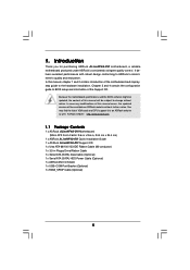
... select "Realtek HDA Audio 2nd output" to the front panel audio header. TABLE for connection details in accordance with the type of speaker you use. 1.5 ASRock DVI I/O 1 2 3 4 7 5 8 6 9 13 12 11 10 1 PS/2 Mouse Port (Green) 2 Parallel Port 3 RJ-45 Port 4 Side Speaker (Gray) 5 Rear Speaker (Black...) 6 Central / Bass (Orange) 7 Line In (Light Blue) * 8 Front Speaker (Lime) 9 Microphone (Pink) 10 USB 2.0 Ports (USB01) 11 VGA/D-Sub Port 12 VGA/DVI-D Port 13 PS/2 Keyboard Port (Purple) * If you use front panel audio. 11 Please select "Mixer ToolBox" , click "Enable ...
... select "Realtek HDA Audio 2nd output" to the front panel audio header. TABLE for connection details in accordance with the type of speaker you use. 1.5 ASRock DVI I/O 1 2 3 4 7 5 8 6 9 13 12 11 10 1 PS/2 Mouse Port (Green) 2 Parallel Port 3 RJ-45 Port 4 Side Speaker (Gray) 5 Rear Speaker (Black...) 6 Central / Bass (Orange) 7 Line In (Light Blue) * 8 Front Speaker (Lime) 9 Microphone (Pink) 10 USB 2.0 Ports (USB01) 11 VGA/D-Sub Port 12 VGA/DVI-D Port 13 PS/2 Keyboard Port (Purple) * If you use front panel audio. 11 Please select "Mixer ToolBox" , click "Enable ...

User Manual
Page 18
... . Use Surround Display. However, please do the clear-CMOS action. 18 If no jumper cap is placed on these 2 pins. After waiting for PS/2 or USB wake up the system first, and then shut it requires 2 Amp and higher standby current provided by power supply. The illustration shows a 3-pin jumper whose...
... . Use Surround Display. However, please do the clear-CMOS action. 18 If no jumper cap is placed on these 2 pins. After waiting for PS/2 or USB wake up the system first, and then shut it requires 2 Amp and higher standby current provided by power supply. The illustration shows a 3-pin jumper whose...

User Manual
Page 20
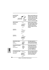
...-ROM, TV tuner card, or MPEG card. This header supports an optional wireless transmitting and receiving infrared module. Each USB 2.0 header can support two USB 2.0 ports. This is an interface for the front panel audio cable that allows convenient connection and control of the power... supply. Serial ATA (SATA) Power Cable (Optional) connect to the SATA HDD power connector connect to the power supply USB 2.0 Headers (9-pin USB6_7) (see p.10 No. 15) USB_PWR P-7 P+7 GND DUMMY 1 GND P+6 P-6 USB_PWR (9-pin USB4_5) (see p.10 No. 17) USB_PWR P-5 P+5 GND...
...-ROM, TV tuner card, or MPEG card. This header supports an optional wireless transmitting and receiving infrared module. Each USB 2.0 header can support two USB 2.0 ports. This is an interface for the front panel audio cable that allows convenient connection and control of the power... supply. Serial ATA (SATA) Power Cable (Optional) connect to the SATA HDD power connector connect to the power supply USB 2.0 Headers (9-pin USB6_7) (see p.10 No. 15) USB_PWR P-7 P+7 GND DUMMY 1 GND P+6 P-6 USB_PWR (9-pin USB4_5) (see p.10 No. 17) USB_PWR P-5 P+5 GND...

User Manual
Page 23
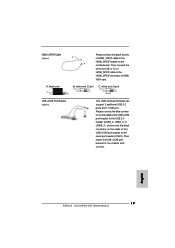
... GND blue black C. Please connect the blue connector on the cable of this USB+COM port bracket to the USB 2.0 header (USB2_3, USB4_5, or USB6_7), and connect the black connector on the cable of this USB+COM port bracket to the HDMI_SPDIF header on the motherboard. A. black end +... to the serial port header (COM1). white end (3-pin) SPDIFOUT GND blue black USB+COM Port Bracket (Optional) This USB+COM port bracket can support 2 additional USB 2.0 ports and 1 COM port. Then fasten the USB+COM port bracket to the HDMI_SPDIF connector of HDMI_SPDIF cable to the chassis with screws....
... GND blue black C. Please connect the blue connector on the cable of this USB+COM port bracket to the USB 2.0 header (USB2_3, USB4_5, or USB6_7), and connect the black connector on the cable of this USB+COM port bracket to the HDMI_SPDIF header on the motherboard. A. black end +... to the serial port header (COM1). white end (3-pin) SPDIFOUT GND blue black USB+COM Port Bracket (Optional) This USB+COM port bracket can support 2 additional USB 2.0 ports and 1 COM port. Then fasten the USB+COM port bracket to the HDMI_SPDIF connector of HDMI_SPDIF cable to the chassis with screws....

User Manual
Page 31
...frequency. CPU Configuration Chipset Configuration ACPI Configuration IDE Configuration PCIPnP Configuration Floppy Configuration SuperIO Configuration USB Configuration Options for the following items: CPU Configuration, Chipset Configuration, ACPI Configuration, IDE Configuration, PCIPnP Configuration, Floppy ...Configuration, SuperIO Configuration, and USB Configuration. BIOS SETUP UTILITY Overclock Mode Use this to malfunction. Setting wrong values in this section may...
...frequency. CPU Configuration Chipset Configuration ACPI Configuration IDE Configuration PCIPnP Configuration Floppy Configuration SuperIO Configuration USB Configuration Options for the following items: CPU Configuration, Chipset Configuration, ACPI Configuration, IDE Configuration, PCIPnP Configuration, Floppy ...Configuration, SuperIO Configuration, and USB Configuration. BIOS SETUP UTILITY Overclock Mode Use this to malfunction. Setting wrong values in this section may...

User Manual
Page 40
.... Configuration options: [Disabled], [300], and [330]. 3.3.8 USB Configuration BIOS SETUP UTILITY Advanced USB Configuration USB Controller USB 2.0 Support Legacy USB Support [Enabled] [Enabled] [Disabled] To enable or disable the onboard USB controllers. +F1 F9 F10 ESC Select Screen Select Item Change Option...parallel port. Configuration options: [Disabled], [378], and [278]. Parallel Port Address Use this item to set the operation mode of USB controller. Configuration options: [Normal], [Bi-Directional], and [ECP+EPP]. Configuration options: [IRQ5] and [IRQ7]. OnBoard Game Port ...
.... Configuration options: [Disabled], [300], and [330]. 3.3.8 USB Configuration BIOS SETUP UTILITY Advanced USB Configuration USB Controller USB 2.0 Support Legacy USB Support [Enabled] [Enabled] [Disabled] To enable or disable the onboard USB controllers. +F1 F9 F10 ESC Select Screen Select Item Change Option...parallel port. Configuration options: [Disabled], [378], and [278]. Parallel Port Address Use this item to set the operation mode of USB controller. Configuration options: [Normal], [Bi-Directional], and [ECP+EPP]. Configuration options: [IRQ5] and [IRQ7]. OnBoard Game Port ...

User Manual
Page 41
...allows you to monitor the status of the hardware on your system, including the parameters of legacy OS (DOS) such as mouse, keyboard, USB flash... CPU Ambient Temperature This item shows the temperature sensed by dual current source CPU. if there is [Disabled]. 41 etc. Configuration ...devices of the CPU temperature, motherboard temperature, CPU fan speed, chassis fan speed, and the critical voltage. The default value is no USB device connected, "Auto" option will start to identify the temperature of CPU fan. CPU Internal Temperature This item shows the temperature sensed ...
...allows you to monitor the status of the hardware on your system, including the parameters of legacy OS (DOS) such as mouse, keyboard, USB flash... CPU Ambient Temperature This item shows the temperature sensed by dual current source CPU. if there is [Disabled]. 41 etc. Configuration ...devices of the CPU temperature, motherboard temperature, CPU fan speed, chassis fan speed, and the critical voltage. The default value is no USB device connected, "Auto" option will start to identify the temperature of CPU fan. CPU Internal Temperature This item shows the temperature sensed ...

Quick Installation Guide
Page 2
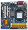
... (USB4_5, Blue) 3 ATX 12V Power Connector (ATX12V1) 18 CPU Fan Connector (CPU_FAN1) 4 CPU Heatsink Retention Module 19 USB 2.0 Header (USB2_3, Blue) 5 AM2 940-Pin CPU Socket 20 Clear CMOS Jumper (CLRCMOS1) 6 2 x 240-pin DDRII DIMM Slots 21 ...Header (SPEAKER 1) 30 PCI Express x16 Slot (PCIE1) 14 Chassis Fan Connector (CHA_FAN1) 31 Internal Audio Connector: CD1 (Black) 15 USB 2.0 Header (USB6_7, Blue) 32 North Bridge Controller 2 ASRock ALiveNF4G-DVI Motherboard Yellow) 22 Floppy Connector (FLOPPY1) 7 2 x 240-pin DDRII DIMM Slots 23 Flash Memory (Dual Channel B: DDRII_3, DDRII_4;...
... (USB4_5, Blue) 3 ATX 12V Power Connector (ATX12V1) 18 CPU Fan Connector (CPU_FAN1) 4 CPU Heatsink Retention Module 19 USB 2.0 Header (USB2_3, Blue) 5 AM2 940-Pin CPU Socket 20 Clear CMOS Jumper (CLRCMOS1) 6 2 x 240-pin DDRII DIMM Slots 21 ...Header (SPEAKER 1) 30 PCI Express x16 Slot (PCIE1) 14 Chassis Fan Connector (CHA_FAN1) 31 Internal Audio Connector: CD1 (Black) 15 USB 2.0 Header (USB6_7, Blue) 32 North Bridge Controller 2 ASRock ALiveNF4G-DVI Motherboard Yellow) 22 Floppy Connector (FLOPPY1) 7 2 x 240-pin DDRII DIMM Slots 23 Flash Memory (Dual Channel B: DDRII_3, DDRII_4;...
Quick Installation Guide
Page 3
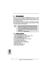
... cable to use front panel audio. 3 ASRock ALiveNF4G-DVI Motherboard English ASRock DVI I/O 1 PS/2 Mouse Port (Green) 2 Parallel Port 3 RJ-45 Port 4 Side Speaker (Gray) 5 Rear Speaker (Black) 6 Central / Bass (Orange) 7 Line In (Light Blue) * 8 Front Speaker (Lime) 9 Microphone (Pink) 10 USB 2.0 Ports (USB01) 11 VGA/D-Sub Port 12 VGA/DVI-D Port 13 PS/2 Keyboard Port (Purple...
... cable to use front panel audio. 3 ASRock ALiveNF4G-DVI Motherboard English ASRock DVI I/O 1 PS/2 Mouse Port (Green) 2 Parallel Port 3 RJ-45 Port 4 Side Speaker (Gray) 5 Rear Speaker (Black) 6 Central / Bass (Orange) 7 Line In (Light Blue) * 8 Front Speaker (Lime) 9 Microphone (Pink) 10 USB 2.0 Ports (USB01) 11 VGA/D-Sub Port 12 VGA/DVI-D Port 13 PS/2 Keyboard Port (Purple...
Quick Installation Guide
Page 4
...the motherboard can be subject to quality and endurance. ASRock website http://www.asrock.com 1.1 Package Contents 1 x ASRock ALiveNF4G-DVI Motherboard (Micro ATX Form Factor: 9.6-in x 9.6-in, 24.4 cm x 24.4 cm) 1 x ASRock ALiveNF4G-DVI Quick Installation Guide 1 x ASRock ALiveNF4G-DVI Support CD 1 x Ultra ATA 66/100/133 ...) Data Cable (Optional) 1 x Serial ATA (SATA) HDD Power Cable (Optional) 1 x ASRock DVI I/O Shield 1 x USB+COM Port Bracket (Optional) 1 x HDMI_SPDIF Cable (Optional) 4 ASRock ALiveNF4G-DVI Motherboard English You may find the latest VGA cards and CPU support lists on...
...the motherboard can be subject to quality and endurance. ASRock website http://www.asrock.com 1.1 Package Contents 1 x ASRock ALiveNF4G-DVI Motherboard (Micro ATX Form Factor: 9.6-in x 9.6-in, 24.4 cm x 24.4 cm) 1 x ASRock ALiveNF4G-DVI Quick Installation Guide 1 x ASRock ALiveNF4G-DVI Support CD 1 x Ultra ATA 66/100/133 ...) Data Cable (Optional) 1 x Serial ATA (SATA) HDD Power Cable (Optional) 1 x ASRock DVI I/O Shield 1 x USB+COM Port Bracket (Optional) 1 x HDMI_SPDIF Cable (Optional) 4 ASRock ALiveNF4G-DVI Motherboard English You may find the latest VGA cards and CPU support lists on...
Quick Installation Guide
Page 6
...Events - Drivers, Utilities, AntiVirus Software (Trial Version) - FCC, CE, Microsoft® WHQL Certificated English 6 ASRock ALiveNF4G-DVI Motherboard Front panel audio connector - 3 x USB 2.0 headers (support 6 USB 2.0 ports) (see CAUTION 9) - AMI Legal BIOS - Supports "Plug and Play" - Chassis Fan Tachometer ... - CPU Ambient Temperature Sensing - Connector BIOS Feature Support CD Hardware Monitor OS Certifications - 4 x Ready-to-Use USB 2.0 Ports (including 2 ports on bundled USB+COM port bracket) - 1 x RJ-45 Port - CD in /Front Speaker/Microphone (see CAUTION 6) - 2...
...Events - Drivers, Utilities, AntiVirus Software (Trial Version) - FCC, CE, Microsoft® WHQL Certificated English 6 ASRock ALiveNF4G-DVI Motherboard Front panel audio connector - 3 x USB 2.0 headers (support 6 USB 2.0 ports) (see CAUTION 9) - AMI Legal BIOS - Supports "Plug and Play" - Chassis Fan Tachometer ... - CPU Ambient Temperature Sensing - Connector BIOS Feature Support CD Hardware Monitor OS Certifications - 4 x Ready-to-Use USB 2.0 Ports (including 2 ports on bundled USB+COM port bracket) - 1 x RJ-45 Port - CD in /Front Speaker/Microphone (see CAUTION 6) - 2...
Quick Installation Guide
Page 7
... to spray thermal grease between the CPU and the heatsink when you resume the system, please check if the CPU fan on page 10 for USB 2.0 works fine under Windows system. For power-saving's sake, it to SATAII mode. To improve heat dissipation, remember to SATAII connector directly. 8. We will update... driver is not recommended to enable AMD's Cool 'n' QuietTM technology under Microsoft® Windows® VistaTM / XP 64-bit / XP SP1 or SP2 / 2000 SP4. 9. ASRock website http://www.asrock.com 7 ASRock ALiveNF4G-DVI Motherboard English
... to spray thermal grease between the CPU and the heatsink when you resume the system, please check if the CPU fan on page 10 for USB 2.0 works fine under Windows system. For power-saving's sake, it to SATAII mode. To improve heat dissipation, remember to SATAII connector directly. 8. We will update... driver is not recommended to enable AMD's Cool 'n' QuietTM technology under Microsoft® Windows® VistaTM / XP 64-bit / XP SP1 or SP2 / 2000 SP4. 9. ASRock website http://www.asrock.com 7 ASRock ALiveNF4G-DVI Motherboard English
Quick Installation Guide
Page 14
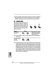
.... Note: To select +5VSB, it down before you move items from the power supply. After waiting for 15 seconds, use . English 14 ASRock ALiveNF4G-DVI Motherboard Short Open Jumper Setting PS2_USB_PW1 Short pin2, pin3 to another. 2.5 Jumpers Setup The illustration shows how jumpers are "Short" when jumper cap is... "Open". Use Surround Display. When the jumper cap is placed on pins, the jumper is placed on CLRCMOS1 for PS/2 or USB wake up the system first, and then shut it requires 2 Amp and higher standby current provided by power supply. The illustration shows a...
.... Note: To select +5VSB, it down before you move items from the power supply. After waiting for 15 seconds, use . English 14 ASRock ALiveNF4G-DVI Motherboard Short Open Jumper Setting PS2_USB_PW1 Short pin2, pin3 to another. 2.5 Jumpers Setup The illustration shows how jumpers are "Short" when jumper cap is... "Open". Use Surround Display. When the jumper cap is placed on pins, the jumper is placed on CLRCMOS1 for PS/2 or USB wake up the system first, and then shut it requires 2 Amp and higher standby current provided by power supply. The illustration shows a...
Quick Installation Guide
Page 16
... connector of the power supply. This is an interface for the front panel audio cable that allows convenient connection and control of audio devices. 16 ASRock ALiveNF4G-DVI Motherboard USB 2.0 Headers (9-pin USB6_7) (see p.2, No. 26) This header supports an optional wireless transmitting and receiving infrared module. Then connect the white end of SATA...
... connector of the power supply. This is an interface for the front panel audio cable that allows convenient connection and control of audio devices. 16 ASRock ALiveNF4G-DVI Motherboard USB 2.0 Headers (9-pin USB6_7) (see p.2, No. 26) This header supports an optional wireless transmitting and receiving infrared module. Then connect the white end of SATA...
Quick Installation Guide
Page 19
... ASRock ALiveNF4G-DVI Motherboard B. Please connect the blue connector on the cable of this USB+COM port bracket to the HDMI_SPDIF header on the cable of HDMI VGA card. white end (2-pin) C. white end (3-pin) USB+COM Port Bracket (Optional) This USB+COM port bracket can support 2 additional USB ...2.0 ports and 1 COM port. black end C B A Please connect the black end (A) of HDMI_SPDIF cable to the USB 2.0 header (USB2_3, USB4_5, or USB6_7), and ...
... ASRock ALiveNF4G-DVI Motherboard B. Please connect the blue connector on the cable of this USB+COM port bracket to the HDMI_SPDIF header on the cable of HDMI VGA card. white end (2-pin) C. white end (3-pin) USB+COM Port Bracket (Optional) This USB+COM port bracket can support 2 additional USB ...2.0 ports and 1 COM port. black end C B A Please connect the black end (A) of HDMI_SPDIF cable to the USB 2.0 header (USB2_3, USB4_5, or USB6_7), and ...


