RAID Installation Guide
Page 8
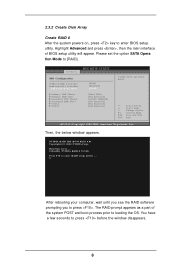
...you see the RAID software prompting you to enter RAID setup utility . . . 2.3.2 Create Disk Array Create RAID 0 After the system powers on, press key to loading the OS. The RAID prompt appears as a part of BIOS setup utility will appear. Advanced BIOS SETUP UTILITY IDE Configuration OnBoard IDE Controller OnBoard SATA Controller SATA Operation Mode Primary IDE Master Primary IDE Slave Secondary IDE Master Secondary IDE Slave SATA1 SATA2 [Both] [Enabled] [RAID] [Hard Disk] [Not Detected] [ATAPI CDROM] [Not Detected] [Not Detected] [Not Detected] Config SATA operation mode. +F1 F10...
...you see the RAID software prompting you to enter RAID setup utility . . . 2.3.2 Create Disk Array Create RAID 0 After the system powers on, press key to loading the OS. The RAID prompt appears as a part of BIOS setup utility will appear. Advanced BIOS SETUP UTILITY IDE Configuration OnBoard IDE Controller OnBoard SATA Controller SATA Operation Mode Primary IDE Master Primary IDE Slave Secondary IDE Master Secondary IDE Slave SATA1 SATA2 [Both] [Enabled] [RAID] [Hard Disk] [Not Detected] [ATAPI CDROM] [Not Detected] [Not Detected] [Not Detected] Config SATA operation mode. +F1 F10...
RAID Installation Guide
Page 12
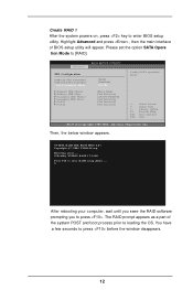
... until you seee the RAID software prompting you to [RAID]. Detecting array . . . 0 Healthy NVIDIA RAID 1 74.54G Press F10 to enter BIOS setup utility. American Megatrends, Inc. NVIDIA RAID IDE ROM BIOS 4.81 Copyright (C) 2004 NVIDIA Corp. Create RAID 1 After the system powers on, press key to enter RAID setup utility . . . Advanced BIOS SETUP UTILITY IDE Configuration OnBoard IDE Controller OnBoard SATA Controller SATA Operation Mode Primary IDE Master Primary IDE Slave Secondary IDE Master Secondary IDE Slave SATA1 SATA2 [Both] [Enabled] [RAID] [Hard Disk] [Not Detected] [ATAPI...
... until you seee the RAID software prompting you to [RAID]. Detecting array . . . 0 Healthy NVIDIA RAID 1 74.54G Press F10 to enter BIOS setup utility. American Megatrends, Inc. NVIDIA RAID IDE ROM BIOS 4.81 Copyright (C) 2004 NVIDIA Corp. Create RAID 1 After the system powers on, press key to enter RAID setup utility . . . Advanced BIOS SETUP UTILITY IDE Configuration OnBoard IDE Controller OnBoard SATA Controller SATA Operation Mode Primary IDE Master Primary IDE Slave Secondary IDE Master Secondary IDE Slave SATA1 SATA2 [Both] [Enabled] [RAID] [Hard Disk] [Not Detected] [ATAPI...
RAID Installation Guide
Page 15
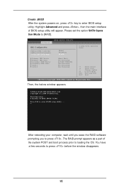
... enter BIOS setup utility. Advanced BIOS SETUP UTILITY IDE Configuration OnBoard IDE Controller OnBoard SATA Controller SATA Operation Mode Primary IDE Master Primary IDE Slave Secondary IDE Master Secondary IDE Slave SATA1 SATA2 [Both] [Enabled] [RAID] [Hard Disk] [Not Detected] [ATAPI CDROM] [Not Detected] [Not Detected] [Not Detected] Config SATA operation mode. +F1 F10 ESC Select Screen Select Item Change Option General Help Save and Exit Exit v02.53 (C) Copyright 1985-2004. Create JBOD After the system powers on, press key to enter RAID setup utility . . . The RAID...
... enter BIOS setup utility. Advanced BIOS SETUP UTILITY IDE Configuration OnBoard IDE Controller OnBoard SATA Controller SATA Operation Mode Primary IDE Master Primary IDE Slave Secondary IDE Master Secondary IDE Slave SATA1 SATA2 [Both] [Enabled] [RAID] [Hard Disk] [Not Detected] [ATAPI CDROM] [Not Detected] [Not Detected] [Not Detected] Config SATA operation mode. +F1 F10 ESC Select Screen Select Item Change Option General Help Save and Exit Exit v02.53 (C) Copyright 1985-2004. Create JBOD After the system powers on, press key to enter RAID setup utility . . . The RAID...

User Manual
Page 8
... over-clocking. Before installing SATAII hard disk to SATAII connector, please read "Untied Overclocking Technology" on page 11 for Microsoft® Windows® VistaTM driver and related information. Power Management for details. 3. This motherboard supports Dual Channel Memory Technology. Before you resume the system, please check if the CPU fan on page 25 to adjust your SATAII hard disk drive to SATAII connector directly. 8. For audio output, this motherboard supports both stereo and mono modes. ASRock website...
... over-clocking. Before installing SATAII hard disk to SATAII connector, please read "Untied Overclocking Technology" on page 11 for Microsoft® Windows® VistaTM driver and related information. Power Management for details. 3. This motherboard supports Dual Channel Memory Technology. Before you resume the system, please check if the CPU fan on page 25 to adjust your SATAII hard disk drive to SATAII connector directly. 8. For audio output, this motherboard supports both stereo and mono modes. ASRock website...

User Manual
Page 16
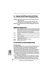
... (PCIE x1 slot) is unplugged. Remove the system unit cover (if your system boots. Step 4. Step 5. Connect the DVI-D input monitor cable to the VGA/DVI-D port on the I /O panel of this motherboard. Step 2. Align the card connector with the slot and press firmly until the card is already installed in a chassis). Replace the system cover. 2.5 Dual Monitor and Surround Display Features Dual Monitor Feature This motherboard supports dual monitor feature. 2.4 Expansion Slots (PCI Express Slots and PCI Slots) There are used to install expansion cards that have installed onboard VGA driver...
... (PCIE x1 slot) is unplugged. Remove the system unit cover (if your system boots. Step 4. Step 5. Connect the DVI-D input monitor cable to the VGA/DVI-D port on the I /O panel of this motherboard. Step 2. Align the card connector with the slot and press firmly until the card is already installed in a chassis). Replace the system cover. 2.5 Dual Monitor and Surround Display Features Dual Monitor Feature This motherboard supports dual monitor feature. 2.4 Expansion Slots (PCI Express Slots and PCI Slots) There are used to install expansion cards that have installed onboard VGA driver...

User Manual
Page 21
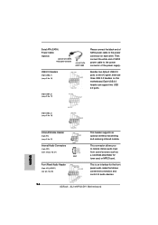
...[Enabled]. D. F. Please connect the chassis speaker to this motherboard provides 4-Pin CPU fan (Quiet Fan) support, the 3-Pin CPU fan still can work successfully even without the fan speed control function. Enter Windows system. Please connect a chassis fan cable to this connector and match the black wire to the front panel audio header as below: A. If you use AC'97 audio panel, please install it to the ground pin. Connect Mic_IN (MIC) to install your system. 2. B. Click "Audio I/O", select "Connector Settings" , choose "Disable front panel jack detection", and save the change...
...[Enabled]. D. F. Please connect the chassis speaker to this motherboard provides 4-Pin CPU fan (Quiet Fan) support, the 3-Pin CPU fan still can work successfully even without the fan speed control function. Enter Windows system. Please connect a chassis fan cable to this connector and match the black wire to the front panel audio header as below: A. If you use AC'97 audio panel, please install it to the ground pin. Connect Mic_IN (MIC) to install your system. 2. B. Click "Audio I/O", select "Connector Settings" , choose "Disable front panel jack detection", and save the change...

User Manual
Page 24
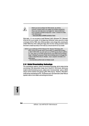
... wrong connector of PCI Express VGA card. For the pin definition of HDMI VGA card, please refer to the installation guide on HDMI VGA card, please refer to the VGA card user manual for detailed connection procedures. white end (2-pin) (B) white end (3-pin) (C) Step 4. Incorrect connection may be damaged. Install HDMI VGA card driver to page 22. Step 3. A complete HDMI system requires a HDMI VGA card and a HDMI ready motherboard with a HDMI_SPDIF header, which provides an interface between any compatible digital audio/video source, such as a set-top box, DVD...
... wrong connector of PCI Express VGA card. For the pin definition of HDMI VGA card, please refer to the installation guide on HDMI VGA card, please refer to the VGA card user manual for detailed connection procedures. white end (2-pin) (B) white end (3-pin) (C) Step 4. Incorrect connection may be damaged. Install HDMI VGA card driver to page 22. Step 3. A complete HDMI system requires a HDMI VGA card and a HDMI ready motherboard with a HDMI_SPDIF header, which provides an interface between any compatible digital audio/video source, such as a set-top box, DVD...

User Manual
Page 26
... hard disk. 2.11 Hot Plug and Hot Swap Functions for SATA / SATAII HDDs This motherboard supports Hot Plug and Hot Swap functions for SATA / SATAII Devices. What is Hot Plug Function? If SATA / SATAII HDDs are NOT set for RAID configuration, it is called "Hot Plug" for internal storage devices. Then, the drivers compatible to insert and remove the SATA / SATAII HDDs while the system is still power-on and in working condition. 2.10 Serial ATA (SATA) / Serial ATAII (SATAII) Hard Disks Installation...
... hard disk. 2.11 Hot Plug and Hot Swap Functions for SATA / SATAII HDDs This motherboard supports Hot Plug and Hot Swap functions for SATA / SATAII Devices. What is Hot Plug Function? If SATA / SATAII HDDs are NOT set for RAID configuration, it is called "Hot Plug" for internal storage devices. Then, the drivers compatible to insert and remove the SATA / SATAII HDDs while the system is still power-on and in working condition. 2.10 Serial ATA (SATA) / Serial ATAII (SATAII) Hard Disks Installation...

User Manual
Page 28
... from [Auto] to install a third-party SCSI or RAID driver. Before you enable Untied Overclocking function, please enter "Overclock Mode" option of Windows® setup, press F6 to [CPU, PCIE, Async.]. Before you start to configure the RAID function, you need to check the installation guide in the Support CD for Windows Guide 2.15 Untied Overclocking Technology This motherboard supports Untied Overclocking Technology, which means during overclocking, but PCI / PCIE buses are in the folder at the following path: .. \Information\Manual\RAID Installation Guide After...
... from [Auto] to install a third-party SCSI or RAID driver. Before you enable Untied Overclocking function, please enter "Overclock Mode" option of Windows® setup, press F6 to [CPU, PCIE, Async.]. Before you start to configure the RAID function, you need to check the installation guide in the Support CD for Windows Guide 2.15 Untied Overclocking Technology This motherboard supports Untied Overclocking Technology, which means during overclocking, but PCI / PCIE buses are in the folder at the following path: .. \Information\Manual\RAID Installation Guide After...

User Manual
Page 36
... F9 F10 ESC Select Screen Select Item Change Option General Help Load Defaults Save and Exit Exit v02.54 (C) Copyright 1985-2003, American Megatrends, Inc. PS/2 Keyboard Power On Use this item to enable or disable PS/2 keyboard to submit Windows® VistaTM certification. 3.3.4 IDE Configuration Advanced BIOS SETUP UTILITY IDE Configuration OnBoard IDE Controller OnBoard SATA Controller SATA Operation Mode HDD Fast Detection Primary IDE Master Primary IDE Slave Secondary IDE Master Secondary IDE Slave SATAII 1 SATAII 2 [Both] [Enabled] [non-RAID] [Disabled] [Hard Disk] [Not Detected...
... F9 F10 ESC Select Screen Select Item Change Option General Help Load Defaults Save and Exit Exit v02.54 (C) Copyright 1985-2003, American Megatrends, Inc. PS/2 Keyboard Power On Use this item to enable or disable PS/2 keyboard to submit Windows® VistaTM certification. 3.3.4 IDE Configuration Advanced BIOS SETUP UTILITY IDE Configuration OnBoard IDE Controller OnBoard SATA Controller SATA Operation Mode HDD Fast Detection Primary IDE Master Primary IDE Slave Secondary IDE Master Secondary IDE Slave SATAII 1 SATAII 2 [Both] [Enabled] [non-RAID] [Disabled] [Hard Disk] [Not Detected...

User Manual
Page 38
... cards' specifications require other settings. Configuration options: [Disabled], [Auto], [Enabled]. 32Bit Data Transfer Use this item to enable or disable the PCI IDE BusMaster feature. 38 PCI Latency Timer PCI IDE BusMaster [64] [Enabled] +F1 F9 F10 ESC Select Screen Select Item Change Option General Help Load Defaults Save and Exit Exit v02.54 (C) Copyright 1985-2003, American Megatrends, Inc. PCI IDE BusMaster Use this item to enable 32-bit access to maximize the IDE hard disk data transfer rate. 3.3.5 PCIPnP Configuration BIOS SETUP UTILITY...
... cards' specifications require other settings. Configuration options: [Disabled], [Auto], [Enabled]. 32Bit Data Transfer Use this item to enable or disable the PCI IDE BusMaster feature. 38 PCI Latency Timer PCI IDE BusMaster [64] [Enabled] +F1 F9 F10 ESC Select Screen Select Item Change Option General Help Load Defaults Save and Exit Exit v02.54 (C) Copyright 1985-2003, American Megatrends, Inc. PCI IDE BusMaster Use this item to enable 32-bit access to maximize the IDE hard disk data transfer rate. 3.3.5 PCIPnP Configuration BIOS SETUP UTILITY...

User Manual
Page 45
... ASRock Express GbL PCI Express LAN card driver if the system detects the installed devices. The CD automatically displays the Main Menu if "AUTORUN" is enabled in your dealer for general reference only. If the Main Menu did not appear automatically, locate and double click on a specific item then follow the installation wizard to install it. 4.2.4 Contact Information If you may contact your computer. Because motherboard settings and hardware options vary, use the setup...
... ASRock Express GbL PCI Express LAN card driver if the system detects the installed devices. The CD automatically displays the Main Menu if "AUTORUN" is enabled in your dealer for general reference only. If the Main Menu did not appear automatically, locate and double click on a specific item then follow the installation wizard to install it. 4.2.4 Contact Information If you may contact your computer. Because motherboard settings and hardware options vary, use the setup...

User Manual
Page 46
... Settings, then Control Panel. 2. Switch to enable AMD's Cool 'n' QuietTM technology under Windows® system. The following dialog box appears. 5. Double-click the Display icon in the Control Panel then select the Screen Saver tab. 4. Click the "Power..." From the Power schemes combo list box, select Minimal Power Management. 6. If you are using this feature, please make sure to install "AMD Processor Driver" from the "Support CD" first. Click OK to enable AMD's Cool...
... Settings, then Control Panel. 2. Switch to enable AMD's Cool 'n' QuietTM technology under Windows® system. The following dialog box appears. 5. Double-click the Display icon in the Control Panel then select the Screen Saver tab. 4. Click the "Power..." From the Power schemes combo list box, select Minimal Power Management. 6. If you are using this feature, please make sure to install "AMD Processor Driver" from the "Support CD" first. Click OK to enable AMD's Cool...

Quick Installation Guide
Page 2
... PCI Slots (PCI1- 2) 13 Chassis Speaker Header (SPEAKER 1) 30 PCI Express x16 Slot (PCIE1) 14 Chassis Fan Connector (CHA_FAN1) 31 Internal Audio Connector: CD1 (Black) 15 USB 2.0 Header (USB6_7, Blue) 32 North Bridge Controller 2 ASRock ALiveNF4G-DVI Motherboard Motherboard Layout English 1 ATX Power Connector (ATXPWR1) 16 South Bridge Controller 2 PS2_USB_PW1 Jumper 17 USB 2.0 Header (USB4_5, Blue) 3 ATX 12V Power Connector (ATX12V1) 18 CPU Fan Connector (CPU_FAN1) 4 CPU Heatsink Retention Module 19 USB 2.0 Header (USB2_3, Blue) 5 AM2 940-Pin CPU Socket 20 Clear CMOS Jumper...
... PCI Slots (PCI1- 2) 13 Chassis Speaker Header (SPEAKER 1) 30 PCI Express x16 Slot (PCIE1) 14 Chassis Fan Connector (CHA_FAN1) 31 Internal Audio Connector: CD1 (Black) 15 USB 2.0 Header (USB6_7, Blue) 32 North Bridge Controller 2 ASRock ALiveNF4G-DVI Motherboard Motherboard Layout English 1 ATX Power Connector (ATXPWR1) 16 South Bridge Controller 2 PS2_USB_PW1 Jumper 17 USB 2.0 Header (USB4_5, Blue) 3 ATX 12V Power Connector (ATX12V1) 18 CPU Fan Connector (CPU_FAN1) 4 CPU Heatsink Retention Module 19 USB 2.0 Header (USB2_3, Blue) 5 AM2 940-Pin CPU Socket 20 Clear CMOS Jumper...
Quick Installation Guide
Page 7
... if the CPU fan on page 3 for proper installation. 4. Power Management for USB 2.0 works fine under Windows system. ASRock website http://www.asrock.com 7 ASRock ALiveNF4G-DVI Motherboard English See APPENDIX on page 10 for proper connection. 7. This motherboard supports Dual Channel Memory Technology. Before you install the PC system. 6. We will automatically shutdown. This motherboard supports Untied Overclocking Technology. Before you implement Dual Channel Memory Technology, make sure to SATAII mode. Before installing SATAII hard disk to SATAII connector, please read...
... if the CPU fan on page 3 for proper installation. 4. Power Management for USB 2.0 works fine under Windows system. ASRock website http://www.asrock.com 7 ASRock ALiveNF4G-DVI Motherboard English See APPENDIX on page 10 for proper connection. 7. This motherboard supports Dual Channel Memory Technology. Before you install the PC system. 6. We will automatically shutdown. This motherboard supports Untied Overclocking Technology. Before you implement Dual Channel Memory Technology, make sure to SATAII mode. Before installing SATAII hard disk to SATAII connector, please read...
Quick Installation Guide
Page 12
... graphics cards. If you can drive same or different display contents. If you have the 32-bit PCI interface. Remove the system unit cover (if your system boots. Connect the D-Sub input monitor cable to support dual VGA output so that the power supply is switched off or the power cord is already installed in a chassis). PCIE Slots: PCIE1 (PCIE x16 slot) is used for DVI-D and D-Sub to the VGA/D-Sub port on ALiveNF4G-DVI motherboard. Step 2. Step 6. Align the card connector...
... graphics cards. If you can drive same or different display contents. If you have the 32-bit PCI interface. Remove the system unit cover (if your system boots. Connect the D-Sub input monitor cable to support dual VGA output so that the power supply is switched off or the power cord is already installed in a chassis). PCIE Slots: PCIE1 (PCIE x16 slot) is used for DVI-D and D-Sub to the VGA/D-Sub port on ALiveNF4G-DVI motherboard. Step 2. Step 6. Align the card connector...
Quick Installation Guide
Page 16
...) Internal Audio Connectors (4-pin CD1) (CD1: see p.2 No. 31) CD1 Front Panel Audio Header (9-pin HD_AUDIO1) (see p.2 No. 15) Besides two default USB 2.0 ports on the I/O panel, there are three USB 2.0 headers on each drive. Serial ATA (SATA) Power Cable (Optional) connect to the SATA HDD power connector connect to the power supply Please connect the black end of SATA power cable to the power connector on this motherboard. Then connect the white end of SATA power cable to receive stereo audio input from sound sources such as a CD-ROM, DVD-ROM, TV tuner card...
...) Internal Audio Connectors (4-pin CD1) (CD1: see p.2 No. 31) CD1 Front Panel Audio Header (9-pin HD_AUDIO1) (see p.2 No. 15) Besides two default USB 2.0 ports on the I/O panel, there are three USB 2.0 headers on each drive. Serial ATA (SATA) Power Cable (Optional) connect to the SATA HDD power connector connect to the power supply Please connect the black end of SATA power cable to the power connector on this motherboard. Then connect the white end of SATA power cable to receive stereo audio input from sound sources such as a CD-ROM, DVD-ROM, TV tuner card...

Quick Installation Guide
Page 20
... system. 20 ASRock ALiveNF4G-DVI Motherboard 2.7 HDMI_SPDIF Header Connection Guide HDMI (High-Definition Multi-media Interface) is equipped with a HDMI_SPDIF header. A complete HDMI system requires a HDMI VGA card and a HDMI ready motherboard with a HDMI_SPDIF header, which provides an interface between any compatible digital audio/video source, such as a set-top box, DVD player, A/V receiver and a compatible digital audio or video monitor, such as HDTV. To use HDMI function on HDMI VGA card, please refer to the fan connector of PCI Express VGA card. For the pin definition of...
... system. 20 ASRock ALiveNF4G-DVI Motherboard 2.7 HDMI_SPDIF Header Connection Guide HDMI (High-Definition Multi-media Interface) is equipped with a HDMI_SPDIF header. A complete HDMI system requires a HDMI VGA card and a HDMI ready motherboard with a HDMI_SPDIF header, which provides an interface between any compatible digital audio/video source, such as a set-top box, DVD player, A/V receiver and a compatible digital audio or video monitor, such as HDTV. To use HDMI function on HDMI VGA card, please refer to the fan connector of PCI Express VGA card. For the pin definition of...
Quick Installation Guide
Page 24
... need to [CPU, PCIE, Async.]. When prompted, insert a floppy disk containing the nVidia® RAID driver. NOTE. Please refer to the document in the fixed mode so that FSB can start to configure the RAID function, you need to set the RAID configuration by using "RAID Utility for Windows Guide 2.14 Untied Overclocking Technology This motherboard supports Untied Overclocking Technology, which is untied during overclocking, but PCI / PCIE buses are in the Support CD, "Guide to SATA Hard Disks Installation and RAID Configuration", which means...
... need to [CPU, PCIE, Async.]. When prompted, insert a floppy disk containing the nVidia® RAID driver. NOTE. Please refer to the document in the fixed mode so that FSB can start to configure the RAID function, you need to set the RAID configuration by using "RAID Utility for Windows Guide 2.14 Untied Overclocking Technology This motherboard supports Untied Overclocking Technology, which is untied during overclocking, but PCI / PCIE buses are in the Support CD, "Guide to SATA Hard Disks Installation and RAID Configuration", which means...
Quick Installation Guide
Page 25
When you start up the computer, please press during the Power-On-Self-Test (POST) to display the menus. 25 ASRock ALiveNF4G-DVI Motherboard English The BIOS Setup program is enabled in your CD-ROM drive. Software Support CD information This motherboard supports various Microsoft® Windows® operating systems: 2000 / XP / XP Media Center / XP 64-bit / VistaTM. EXE" from the "BIN" folder in the Support CD. 4. BIOS Information The Flash Memory on...
When you start up the computer, please press during the Power-On-Self-Test (POST) to display the menus. 25 ASRock ALiveNF4G-DVI Motherboard English The BIOS Setup program is enabled in your CD-ROM drive. Software Support CD information This motherboard supports various Microsoft® Windows® operating systems: 2000 / XP / XP Media Center / XP 64-bit / VistaTM. EXE" from the "BIN" folder in the Support CD. 4. BIOS Information The Flash Memory on...


