
User Manual
Page 1
All rights reserved. 1 ALiveDual-eSATA2 User Manual Version 1.2 Published February 2008 Copyright©2008 ASRock INC.
All rights reserved. 1 ALiveDual-eSATA2 User Manual Version 1.2 Published February 2008 Copyright©2008 ASRock INC.

User Manual
Page 2
...respect to the contents of this manual, ASRock does not provide warranty of any kind, either expressed or implied, including but not limited to infringe. When you discard the Lithium battery in California, USA, please follow the related regulations in this manual are used only for identification or...the FCC Rules. "Perchlorate Material-special handling may apply, see www.dtsc.ca.gov/hazardouswaste/perchlorate" ASRock Website: http://www.asrock.com 2 Products and corporate names appearing in this manual may or may not be liable for any defect or error in any form or by any interference...
...respect to the contents of this manual, ASRock does not provide warranty of any kind, either expressed or implied, including but not limited to infringe. When you discard the Lithium battery in California, USA, please follow the related regulations in this manual are used only for identification or...the FCC Rules. "Perchlorate Material-special handling may apply, see www.dtsc.ca.gov/hazardouswaste/perchlorate" ASRock Website: http://www.asrock.com 2 Products and corporate names appearing in this manual may or may not be liable for any defect or error in any form or by any interference...
User Manual
Page 5
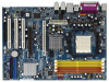
... and endurance. You may find the latest VGA cards and CPU support lists on ASRock website without notice. 1. In this manual, chapter 1 and 2 contain introduction of this motherboard, please visit our website for purchasing ASRock ALiveDual-eSATA2 motherboard, a reliable motherboard produced under ASRock's consistently stringent quality control. In case any modifications of the motherboard and step...
... and endurance. You may find the latest VGA cards and CPU support lists on ASRock website without notice. 1. In this manual, chapter 1 and 2 contain introduction of this motherboard, please visit our website for purchasing ASRock ALiveDual-eSATA2 motherboard, a reliable motherboard produced under ASRock's consistently stringent quality control. In case any modifications of the motherboard and step...

User Manual
Page 13
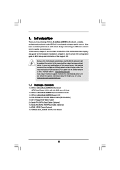
... CPU is in good contact with a small triangle. Step 2. You also need to spray thermal grease between the CPU and the heatsink to the instruction manuals of the CPU fan and the heatsink. 13 DO NOT force the CPU into the socket to indicate that the CPU and the heatsink are...
... CPU is in good contact with a small triangle. Step 2. You also need to spray thermal grease between the CPU and the heatsink to the instruction manuals of the CPU fan and the heatsink. 13 DO NOT force the CPU into the socket to indicate that the CPU and the heatsink are...

User Manual
Page 23
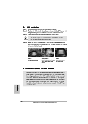
...the motherboard and the HDMI VGA card according to the installation guide on the motherboard. Step 5. Please refer to the VGA card user manual for detailed connection procedures. For the proper installation of HDMI_SPDIF cable to HDMI device, such as a digital television (DTV). white end ...Incorrect connection may be damaged. For the pin definition of HDMI_SPDIF header and HDMI_SPDIF cable connectors, please refer to the user manual of HDMI_SPDIF connectors on this motherboard. Please do not connect the white end of HDMI_SPDIF cable to the HDMI_SPDIF connector of...
...the motherboard and the HDMI VGA card according to the installation guide on the motherboard. Step 5. Please refer to the VGA card user manual for detailed connection procedures. For the proper installation of HDMI_SPDIF cable to HDMI device, such as a digital television (DTV). white end ...Incorrect connection may be damaged. For the pin definition of HDMI_SPDIF header and HDMI_SPDIF cable connectors, please refer to the user manual of HDMI_SPDIF connectors on this motherboard. Please do not connect the white end of HDMI_SPDIF cable to the HDMI_SPDIF connector of...

User Manual
Page 30
... 1x4-pin conventional power connector interface is definitely not able to power supply Caution 1. Below operation procedure is available on our website: www.asrock.com 2. Please follow below instructions step by the chipset because of its limitation, the SATA / SATAII Hot Plug support information of attention,...SATA / SATAII HDD Hot Plug, please check below operation guide of HDD crash or data loss. 30 Make sure your dealer or HDD user manual. Please make sure the SATA / SATAII driver is indicated in RAID / AHCI mode. The latest SATA / SATAII driver is designed only ...
... 1x4-pin conventional power connector interface is definitely not able to power supply Caution 1. Below operation procedure is available on our website: www.asrock.com 2. Please follow below instructions step by the chipset because of its limitation, the SATA / SATAII Hot Plug support information of attention,...SATA / SATAII HDD Hot Plug, please check below operation guide of HDD crash or data loss. 30 Make sure your dealer or HDD user manual. Please make sure the SATA / SATAII driver is indicated in RAID / AHCI mode. The latest SATA / SATAII driver is designed only ...

User Manual
Page 40
...Help Load Defaults Save and Exit Exit v02.54 (C) Copyright 1985-2003, American Megatrends, Inc. Please refer to [Enabled], you will enable ASRock AM2 Boost function, which will be left at the rated frequency/voltage. 3.3 Advanced Screen In this section, you may set based on page... and voltage will be set the configurations for details. Overclock Mode Use this option to malfunction. The default value is [Disabled]. If Manual, multiplier and voltage will improve the memory performance. The default value is [Auto]. Setting wrong values in below sections may cause the ...
...Help Load Defaults Save and Exit Exit v02.54 (C) Copyright 1985-2003, American Megatrends, Inc. Please refer to [Enabled], you will enable ASRock AM2 Boost function, which will be left at the rated frequency/voltage. 3.3 Advanced Screen In this section, you may set based on page... and voltage will be set the configurations for details. Overclock Mode Use this option to malfunction. The default value is [Disabled]. If Manual, multiplier and voltage will improve the memory performance. The default value is [Auto]. Setting wrong values in below sections may cause the ...

User Manual
Page 41
...'n' Quiet Use this option to adjust PCIE frequency. Configuration options: [Enabled] and [Disabled]. Multiplier/Voltage Change This item is set to [Manual], you install Windows® VistaTM and want to enable this function, please set to [Enabled], a VMM (Virtual Machine Architecture) can utilize...Processor Voltage Memory Clock Flexibility Option [Disabled] [Auto] [200] [100] [Auto] [Enabled] [Auto] [Enabled] x10.0 2000 MHz 1.250 V [Manual] [x8] [1.500V] [Auto] [Disabled] If AUTO, multiplier and voltage will be left at the rated frequency/voltage. Boot Failure Guard Enable or ...
...'n' Quiet Use this option to adjust PCIE frequency. Configuration options: [Enabled] and [Disabled]. Multiplier/Voltage Change This item is set to [Manual], you install Windows® VistaTM and want to enable this function, please set to [Enabled], a VMM (Virtual Machine Architecture) can utilize...Processor Voltage Memory Clock Flexibility Option [Disabled] [Auto] [200] [100] [Auto] [Enabled] [Auto] [Enabled] x10.0 2000 MHz 1.250 V [Manual] [x8] [1.500V] [Auto] [Disabled] If AUTO, multiplier and voltage will be left at the rated frequency/voltage. Boot Failure Guard Enable or ...

User Manual
Page 42
Processor Voltage This item will show when "Multiplier/Voltage Change" is set to [Manual]; The range of memory accessing. You can be hidden. CAS Latency (CL) Use this item to adjust the means of the value depends on the .... The default value is [Auto]. TWR Use this to adjust TRP values. Processor Multiplier This item will show when "Multiplier/Voltage Change" is set to [Manual]; However, for safety and system stability, it is [Disabled]. TRP Use this to adjust TRC values. Configuration options: [Auto], [2-4CLK] and [3-5CLK]. Configuration options: [Auto...
Processor Voltage This item will show when "Multiplier/Voltage Change" is set to [Manual]; The range of memory accessing. You can be hidden. CAS Latency (CL) Use this item to adjust the means of the value depends on the .... The default value is [Auto]. TWR Use this to adjust TRP values. Processor Multiplier This item will show when "Multiplier/Voltage Change" is set to [Manual]; However, for safety and system stability, it is [Disabled]. TRP Use this to adjust TRC values. Configuration options: [Auto], [2-4CLK] and [3-5CLK]. Configuration options: [Auto...

Quick Installation Guide
Page 4
... be updated, the content of this motherboard, please visit our website for purchasing ASRock ALiveDual-eSATA2 motherboard, a reliable motherboard produced under ASRock's consistently stringent quality control. This Quick Installation Guide contains introduction of the motherboard can be found in the user manual presented in Floppy Drive Ribbon Cable 2 x Serial ATA (SATA) Data Cables (Optional) 1 x Serial...
... be updated, the content of this motherboard, please visit our website for purchasing ASRock ALiveDual-eSATA2 motherboard, a reliable motherboard produced under ASRock's consistently stringent quality control. This Quick Installation Guide contains introduction of the motherboard can be found in the user manual presented in Floppy Drive Ribbon Cable 2 x Serial ATA (SATA) Data Cables (Optional) 1 x Serial...
Quick Installation Guide
Page 10
... that the CPU and the heatsink are securely fastened and in place, press it firmly on the side tab to secure the CPU. English 10 ASRock ALiveDual-eSATA2 Motherboard Step 3. DO NOT force the CPU into this motherboard, it is locked. Step 4. When the CPU is necessary to install a larger heatsink ... FAN connector (CPU_FAN1, see Page 2, No. 6). The lever clicks on the socket while you install the CPU into the socket to the instruction manuals of CPU Fan and Heatsink After you push down the socket lever to indicate that the CPU corner with the golden triangle matches the socket...
... that the CPU and the heatsink are securely fastened and in place, press it firmly on the side tab to secure the CPU. English 10 ASRock ALiveDual-eSATA2 Motherboard Step 3. DO NOT force the CPU into this motherboard, it is locked. Step 4. When the CPU is necessary to install a larger heatsink ... FAN connector (CPU_FAN1, see Page 2, No. 6). The lever clicks on the socket while you install the CPU into the socket to the instruction manuals of CPU Fan and Heatsink After you push down the socket lever to indicate that the CPU corner with the golden triangle matches the socket...
Quick Installation Guide
Page 20
... VGA card vendor for connector usage in advance. For example, this motherboard. Please refer to the user manual of connecting HDMI_SPDIF cable to the VGA card user manual for detailed connection procedures. A complete HDMI system requires a HDMI VGA card and a HDMI ready motherboard ...HDMI_SPDIF connector of PCI Express VGA card. Otherwise, the motherboard and the VGA card may cause permanent damage to your system. 20 ASRock ALiveDual-eSATA2 Motherboard Please choose the appropriate white end according to the HDMI_SPDIF header (HDMI_SPDIF1, yellow, see page 2, No. 29) on ...
... VGA card vendor for connector usage in advance. For example, this motherboard. Please refer to the user manual of connecting HDMI_SPDIF cable to the VGA card user manual for detailed connection procedures. A complete HDMI system requires a HDMI VGA card and a HDMI ready motherboard ...HDMI_SPDIF connector of PCI Express VGA card. Otherwise, the motherboard and the VGA card may cause permanent damage to your system. 20 ASRock ALiveDual-eSATA2 Motherboard Please choose the appropriate white end according to the HDMI_SPDIF header (HDMI_SPDIF1, yellow, see page 2, No. 29) on ...
Quick Installation Guide
Page 33
...-Test (POST) to display the menus. 33 ASRock ALiveDual-eSATA2 Motherboard English To begin using the Support CD, insert the CD into your computer. The BIOS Setup program is enabled in your CDROM drive. For the detailed information about BIOS Setup, please refer to the User Manual (PDF file) contained in the Support CD...
...-Test (POST) to display the menus. 33 ASRock ALiveDual-eSATA2 Motherboard English To begin using the Support CD, insert the CD into your computer. The BIOS Setup program is enabled in your CDROM drive. For the detailed information about BIOS Setup, please refer to the User Manual (PDF file) contained in the Support CD...

RAID Installation Guide
Page 6
... install identical drives of the data in the other drive if one drive to RAID The term "RAID" stands for "Redundant Array of the "User Manual" in our support CD or "Quick Installation Guide", you to read and write data in this section to configure RAID functions.. 2.1.1 Introduction to a second drive...
... install identical drives of the data in the other drive if one drive to RAID The term "RAID" stands for "Redundant Array of the "User Manual" in our support CD or "Quick Installation Guide", you to read and write data in this section to configure RAID functions.. 2.1.1 Introduction to a second drive...
