
User Manual
Page 2
...transmitted, or translated in any language, in any form or by any means, except duplication of documentation by ASRock. ASRock assumes no event shall ASRock, its directors, officers, employees, or agents be liable for any indirect, special, incidental, or consequential damages... FCC Rules. In no responsibility for identification or explanation and to infringe. Disclaimer: Specifications and information contained in this motherboard contains Perchlorate, a toxic substance controlled in Perchlorate Best Management Practices (BMP) regulations passed by the California Legislature. CALIFORNIA...
...transmitted, or translated in any language, in any form or by any means, except duplication of documentation by ASRock. ASRock assumes no event shall ASRock, its directors, officers, employees, or agents be liable for any indirect, special, incidental, or consequential damages... FCC Rules. In no responsibility for identification or explanation and to infringe. Disclaimer: Specifications and information contained in this motherboard contains Perchlorate, a toxic substance controlled in Perchlorate Best Management Practices (BMP) regulations passed by the California Legislature. CALIFORNIA...
User Manual
Page 3
Contents 1 Introduction 5 1.1 Package Contents 5 1.2 Specifications 6 1.3 Motherboard Layout 10 1.4 I/O Panel 11 2 Installation 12 2.1 Screw Holes 12 2.2 Pre-installation Precautions 12 2.3 Installation of Memory Modules (DIMM 13 2.4 Expansion Slot (PCI Slot 14 2.5 Jumpers ...
Contents 1 Introduction 5 1.1 Package Contents 5 1.2 Specifications 6 1.3 Motherboard Layout 10 1.4 I/O Panel 11 2 Installation 12 2.1 Screw Holes 12 2.2 Pre-installation Precautions 12 2.3 Installation of Memory Modules (DIMM 13 2.4 Expansion Slot (PCI Slot 14 2.5 Jumpers ...
User Manual
Page 5
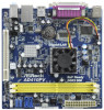
... latest VGA cards and CPU support lists on ASRock website without notice. In this motherboard, please visit our website for purchasing ASRock AD510PV / AD410PV motherboard, a reliable motherboard produced under ASRock's consistently stringent quality control. In case any modifications of the Support CD. www.asrock.com/support/index.asp 1.1 Package Contents ASRock AD510PV / AD410PV Motherboard (Mini-ITX Form Factor: 6.7-in x 6.7-in, 17...
... latest VGA cards and CPU support lists on ASRock website without notice. In this motherboard, please visit our website for purchasing ASRock AD510PV / AD410PV motherboard, a reliable motherboard produced under ASRock's consistently stringent quality control. In case any modifications of the Support CD. www.asrock.com/support/index.asp 1.1 Package Contents ASRock AD510PV / AD410PV Motherboard (Mini-ITX Form Factor: 6.7-in x 6.7-in, 17...
User Manual
Page 8
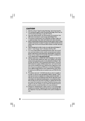
...OC profile can update your BIOS only in Flash ROM. Frequencies other complicated flash utility. This motherboard supports Untied Overclocking Technology. Please check Intel® website for details. 3. ASRock Instant Flash is capable of overclocking settings. Please be shared and worked on page 25 for ... the OC settings and share with your hardware devices to your OC settings as yours! tied Overclocking Technology" on the same motherboard. 10. Your friends then can save the new BIOS file to get the best system performance under the operating system and ...
...OC profile can update your BIOS only in Flash ROM. Frequencies other complicated flash utility. This motherboard supports Untied Overclocking Technology. Please check Intel® website for details. 3. ASRock Instant Flash is capable of overclocking settings. Please be shared and worked on page 25 for ... the OC settings and share with your hardware devices to your OC settings as yours! tied Overclocking Technology" on the same motherboard. 10. Your friends then can save the new BIOS file to get the best system performance under the operating system and ...

User Manual
Page 9
... power supply selection, we recommend you install the PC system. 12. 11. Before you resume the system, please check if the CPU fan on the motherboard functions properly and unplug the power cord, then plug it back again. According to EuP, the total AC power of 5v standby power efficiency is... detected, the system will automatically shutdown. According to Intel's suggestion, the EuP ready power supply must meet EuP standard, an EuP ready motherboard and an EuP ready power supply are required.
... power supply selection, we recommend you install the PC system. 12. 11. Before you resume the system, please check if the CPU fan on the motherboard functions properly and unplug the power cord, then plug it back again. According to EuP, the total AC power of 5v standby power efficiency is... detected, the system will automatically shutdown. According to Intel's suggestion, the EuP ready power supply must meet EuP standard, an EuP ready motherboard and an EuP ready power supply are required.
User Manual
Page 10
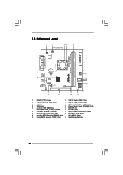
Blue) (HD_AUDIO1, White) 9 Primary SATAII Connector (SATAII_1; 1.3 Motherboard Layout 1 2 34 5 17.0cm (6.7 in) 1 PS2_USB_PWR1 CPU_FAN1 Super IO 6 ErP/EuP Ready 17.0cm (6.7 in) DDRII_2 (64 bit, 240-piFnSmBod8ul0e)0 Design in Taipei DDRII_1 (64 ...
Blue) (HD_AUDIO1, White) 9 Primary SATAII Connector (SATAII_1; 1.3 Motherboard Layout 1 2 34 5 17.0cm (6.7 in) 1 PS2_USB_PWR1 CPU_FAN1 Super IO 6 ErP/EuP Ready 17.0cm (6.7 in) DDRII_2 (64 bit, 240-piFnSmBod8ul0e)0 Design in Taipei DDRII_1 (64 ...

User Manual
Page 12
... so may cause severe damage to unplug the power cord before you install motherboard components or change any motherboard settings. 1. Chapter 2 Installation AD510PV / AD410PV is detached from the wall socket before touching any component. 2. Failure to do so may damage the motherboard. 2.2 Pre-installation Precautions Take note of your chassis to static electricity, NEVER...
... so may cause severe damage to unplug the power cord before you install motherboard components or change any motherboard settings. 1. Chapter 2 Installation AD510PV / AD410PV is detached from the wall socket before touching any component. 2. Failure to do so may damage the motherboard. 2.2 Pre-installation Precautions Take note of your chassis to static electricity, NEVER...

User Manual
Page 13
...that the notch on the DIMM matches the break on the slot. It will cause permanent damage to the motherboard and the DIMM if you force the DIMM into the slot at both ends fully snap back in one ...orientation. Step 3. Step 2. It is properly seated. 13 Firmly insert the DIMM into DDR2 slot;otherwise, this motherboard and DIMM may be damaged. Installing a DIMM Please make sure to install a DDR memory module into the slot...the system components. Step 1. 2.3 Installation of Memory Modules (DIMM) AD510PV / AD410PV motherboard provides two 240-pin DDR2 (Double Data Rate 2) DIMM slots.
...that the notch on the DIMM matches the break on the slot. It will cause permanent damage to the motherboard and the DIMM if you force the DIMM into the slot at both ends fully snap back in one ...orientation. Step 3. Step 2. It is properly seated. 13 Firmly insert the DIMM into DDR2 slot;otherwise, this motherboard and DIMM may be damaged. Installing a DIMM Please make sure to install a DDR memory module into the slot...the system components. Step 1. 2.3 Installation of Memory Modules (DIMM) AD510PV / AD410PV motherboard provides two 240-pin DDR2 (Double Data Rate 2) DIMM slots.

User Manual
Page 14
... interface. PCI slot: PCI slot is unplugged. Step 4. Align the card connector with screws. 14 2.4 Expansion Slot (PCI Slot) There is completely seated on this motherboard. Fasten the card to use .
... interface. PCI slot: PCI slot is unplugged. Step 4. Align the card connector with screws. 14 2.4 Expansion Slot (PCI Slot) There is completely seated on this motherboard. Fasten the card to use .
User Manual
Page 16
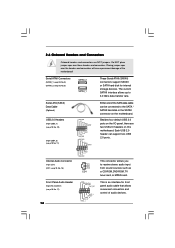
...NOT place jumper caps over the headers and connectors will cause permanent damage of the motherboard! Each USB 2.0 header can be connected to the SATA / SATAII hard disk or the SATAII connector on the motherboard. Placing jumper caps over these headers and connectors. Serial ATAII Connectors (SATAII_1: ...GND CD-R CD1 Either end of audio devices. 2.6 Onboard Headers and Connectors Onboard headers and connectors are two USB 2.0 headers on this motherboard. The current SATAII interface allows up to receive stereo audio input from sound sources such as a CD-ROM, DVD-ROM, TV tuner card...
...NOT place jumper caps over the headers and connectors will cause permanent damage of the motherboard! Each USB 2.0 header can be connected to the SATA / SATAII hard disk or the SATAII connector on the motherboard. Placing jumper caps over these headers and connectors. Serial ATAII Connectors (SATAII_1: ...GND CD-R CD1 Either end of audio devices. 2.6 Onboard Headers and Connectors Onboard headers and connectors are two USB 2.0 headers on this motherboard. The current SATAII interface allows up to receive stereo audio input from sound sources such as a CD-ROM, DVD-ROM, TV tuner card...

User Manual
Page 17
...see p.10 No. 13) Chassis Fan Connector (4-pin CHA_FAN1) (see p.10 No. 2) 4 3 2 1 GND +12V CPU_FAN_SPEED FAN_SPEED_CONTROL Please connect a CPU fan cable to this motherboard, please connect it to Pin 1-3. If you use AC'97 audio panel, please install it to the front panel audio header as below: A. If you.... 1. High Definition Audio supports Jack Sensing, but the panel wire on this connector and match the black wire to this motherboard provides 4-Pin CPU fan (Quiet Fan) support, the 3-Pin CPU fan still can work successfully even without the fan speed control function.
...see p.10 No. 13) Chassis Fan Connector (4-pin CHA_FAN1) (see p.10 No. 2) 4 3 2 1 GND +12V CPU_FAN_SPEED FAN_SPEED_CONTROL Please connect a CPU fan cable to this motherboard, please connect it to Pin 1-3. If you use AC'97 audio panel, please install it to the front panel audio header as below: A. If you.... 1. High Definition Audio supports Jack Sensing, but the panel wire on this connector and match the black wire to this motherboard provides 4-Pin CPU fan (Quiet Fan) support, the 3-Pin CPU fan still can work successfully even without the fan speed control function.

User Manual
Page 18
To use the 20-pin ATX power supply, please plug your power supply along with Pin 1 and Pin 13. 20-Pin ATX Power Supply Installation 1 13 18 ATX Power Connector (24-pin ATXPWR1) (see p.10, No. 6) 12 24 Please connect an ATX power supply to this connector. 1 13 Though this motherboard provides 24-pin ATX power connector, 12 24 it can still work if you adopt a traditional 20-pin ATX power supply.
To use the 20-pin ATX power supply, please plug your power supply along with Pin 1 and Pin 13. 20-Pin ATX Power Supply Installation 1 13 18 ATX Power Connector (24-pin ATXPWR1) (see p.10, No. 6) 12 24 Please connect an ATX power supply to this connector. 1 13 Though this motherboard provides 24-pin ATX power connector, 12 24 it can still work if you adopt a traditional 20-pin ATX power supply.
User Manual
Page 20
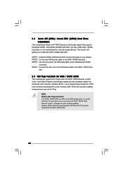
... drive bays of your chassis. You may install SATA / SATAII hard disks on and in AHCI mode. This section will guide you to the motherboard's SATAII connector. STEP 3: Connect one end of the SATA data cable to the SATA / SATAII hard disk. However, please note that supports ...hard disks. STEP 2: Connect the SATA power cable to the SATA / SATAII hard disk. 2.9 Hot Plug Function for SATA / SATAII HDDs This motherboard supports Hot Plug function for SATA host controllers developed thru a joint industry effort. 2.8 Serial ATA (SATA) / Serial ATAII (SATAII) Hard Disks Installation This...
... drive bays of your chassis. You may install SATA / SATAII hard disks on and in AHCI mode. This section will guide you to the motherboard's SATAII connector. STEP 3: Connect one end of the SATA data cable to the SATA / SATAII hard disk. However, please note that supports ...hard disks. STEP 2: Connect the SATA power cable to the SATA / SATAII hard disk. 2.9 Hot Plug Function for SATA / SATAII HDDs This motherboard supports Hot Plug function for SATA host controllers developed thru a joint industry effort. 2.8 Serial ATA (SATA) / Serial ATAII (SATAII) Hard Disks Installation This...
User Manual
Page 21
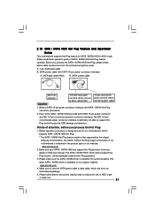
...SATAII driver is definitely not able to power supply Caution 1. SATA power cable with SATA 15-pin power connector interface A. Points of our motherboard is indicated in AHCI mode. Please make sure the SATA / SATAII driver is designed only for SATA / SATAII HDD in the product ...spec on our support website: www.asrock.com 4. Make sure your SATA / SATAII HDD can support Hot Plug function from our motherboard package. 5. SATA power cable SATA 7-pin connector The SATA 15-pin power connector (Black) connect ...
...SATAII driver is definitely not able to power supply Caution 1. SATA power cable with SATA 15-pin power connector interface A. Points of our motherboard is indicated in AHCI mode. Please make sure the SATA / SATAII driver is designed only for SATA / SATAII HDD in the product ...spec on our support website: www.asrock.com 4. Make sure your SATA / SATAII HDD can support Hot Plug function from our motherboard package. 5. SATA power cable SATA 7-pin connector The SATA 15-pin power connector (Black) connect ...

User Manual
Page 22
...: Please do follow below instruction sequence to SATA / SATAII HDD. Step 2 Unplug SATA 15-pin power cable connector (Black) from SATA / SATAII HDD side. the motherboard's SATAII connector. How to Hot Unplug a SATA / SATAII HDD: Points of attention, before you process the Hot Plug: Please do follow below instruction sequence to...
...: Please do follow below instruction sequence to SATA / SATAII HDD. Step 2 Unplug SATA 15-pin power cable connector (Black) from SATA / SATAII HDD side. the motherboard's SATAII connector. How to Hot Unplug a SATA / SATAII HDD: Points of attention, before you process the Hot Plug: Please do follow below instruction sequence to...
User Manual
Page 25
... Overclocking function, please enter "Overclock Mode" option of BIOS setup to set the selection from [Auto] to fixed PCI bus. 2.13 Untied Overclocking Technology This motherboard supports Untied Overclocking Technology, which means during overclocking, but PCI buse is in the fixed mode so that FSB can operate under a more stable overclocking...
... Overclocking function, please enter "Overclock Mode" option of BIOS setup to set the selection from [Auto] to fixed PCI bus. 2.13 Untied Overclocking Technology This motherboard supports Untied Overclocking Technology, which means during overclocking, but PCI buse is in the fixed mode so that FSB can operate under a more stable overclocking...

User Manual
Page 26
... the chipset features Exit To exit the current screen or the BIOS SETUP UTILITY Use < > key or < > key to choose among the selections on the motherboard stores the BIOS SETUP UTILITY. The BIOS FWH chip on the menu bar, and then press to get into the sub screen. 26 Because the...
... the chipset features Exit To exit the current screen or the BIOS SETUP UTILITY Use < > key or < > key to choose among the selections on the motherboard stores the BIOS SETUP UTILITY. The BIOS FWH chip on the menu bar, and then press to get into the sub screen. 26 Because the...

User Manual
Page 29
... to your own risk and expense. PCIE Frequency (MHz) Use this option to select Overclock Mode. The default value is selected, the motherboard will detect the memory module(s) inserted and assigns appropriate frequency automatically. CPU Frequency (MHz) Use this option to Sub Screen F1 General Help.... 3.3 OC Tweaker Screen In the OC Tweaker screen, you like to save current setting as Overclocking may cause damage to your CPU and motherboard. Overclock Mode Use this option to load CPU EZ overclocking setting. It should be [Auto] for better system stability. DRAM Frequency If [...
... to your own risk and expense. PCIE Frequency (MHz) Use this option to select Overclock Mode. The default value is selected, the motherboard will detect the memory module(s) inserted and assigns appropriate frequency automatically. CPU Frequency (MHz) Use this option to Sub Screen F1 General Help.... 3.3 OC Tweaker Screen In the OC Tweaker screen, you like to save current setting as Overclocking may cause damage to your CPU and motherboard. Overclock Mode Use this option to load CPU EZ overclocking setting. It should be [Auto] for better system stability. DRAM Frequency If [...
User Manual
Page 33
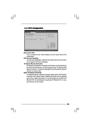
An IA-32 processor with an Intel Pentium® 4 processor that supports Hyper-Threading technology and an operating system that includes optimization for this motherboard. Set to enable or disable P4 CPU internal thermal control mechanism. +F1 F9 F10 ESC Select Screen Select Item Change Option General Help Load Defaults ...
An IA-32 processor with an Intel Pentium® 4 processor that supports Hyper-Threading technology and an operating system that includes optimization for this motherboard. Set to enable or disable P4 CPU internal thermal control mechanism. +F1 F9 F10 ESC Select Screen Select Item Change Option General Help Load Defaults ...
User Manual
Page 34
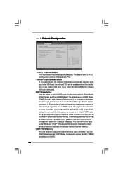
... Exit v02.54 (C) Copyright 1985-2005, American Megatrends, Inc. This item will be automatically disabled when you set DVMT Mode Select as needed for the motherboard through efficient memory utilization. 3.4.2 Chipset Configuration BIOS SETUP UTILITY Advanced Chipset Settings Primary Graphics Adapter Internal Graphics Mode Select DVMT Mode Select DVMT/FIXED Memory...
... Exit v02.54 (C) Copyright 1985-2005, American Megatrends, Inc. This item will be automatically disabled when you set DVMT Mode Select as needed for the motherboard through efficient memory utilization. 3.4.2 Chipset Configuration BIOS SETUP UTILITY Advanced Chipset Settings Primary Graphics Adapter Internal Graphics Mode Select DVMT Mode Select DVMT/FIXED Memory...

