User Manual
Page 1
All rights reserved. 1 AD2550B-ITX User Manual Version 1.0 Published April 2012 Copyright©2012 ASRock INC.
All rights reserved. 1 AD2550B-ITX User Manual Version 1.0 Published April 2012 Copyright©2012 ASRock INC.

User Manual
Page 2
...interference that may appear in this manual may cause undesired operation. CALIFORNIA, USA ONLY The Lithium battery adopted on this manual, ASRock does not provide warranty of any errors or omissions that may be liable for any indirect, special, incidental, or consequential ...contains Perchlorate, a toxic substance controlled in this manual may or may apply, see www.dtsc.ca.gov/hazardouswaste/perchlorate" ASRock Website: http://www.asrock.com 2 Disclaimer: Specifications and information contained in Perchlorate Best Management Practices (BMP) regulations passed by the ...
...interference that may appear in this manual may cause undesired operation. CALIFORNIA, USA ONLY The Lithium battery adopted on this manual, ASRock does not provide warranty of any errors or omissions that may be liable for any indirect, special, incidental, or consequential ...contains Perchlorate, a toxic substance controlled in this manual may or may apply, see www.dtsc.ca.gov/hazardouswaste/perchlorate" ASRock Website: http://www.asrock.com 2 Disclaimer: Specifications and information contained in Perchlorate Best Management Practices (BMP) regulations passed by the ...

User Manual
Page 3
... Layout 10 1.4 I/O Panel 11 2 Installation 12 2.1 Screw Holes 12 2.2 Pre-installation Precautions 12 2.3 Installation of Memory Modules (SO-DIMM 13 2.4 Expansion Slot (PCI Slot 14 2.5 ASRock Smart Remote Installation Guide 15 2.6 Jumpers Setup 17 2.7 Onboard Headers and Connectors 18 2.8 Serial ATA (SATA) / Serial ATA2 (SATA2) Hard Disks Installation 21 2.9 Hot Plug...
... Layout 10 1.4 I/O Panel 11 2 Installation 12 2.1 Screw Holes 12 2.2 Pre-installation Precautions 12 2.3 Installation of Memory Modules (SO-DIMM 13 2.4 Expansion Slot (PCI Slot 14 2.5 ASRock Smart Remote Installation Guide 15 2.6 Jumpers Setup 17 2.7 Onboard Headers and Connectors 18 2.8 Serial ATA (SATA) / Serial ATA2 (SATA2) Hard Disks Installation 21 2.9 Hot Plug...
User Manual
Page 4
4 Software Support 39 4.1 Install Operating System 39 4.2 Support CD Information 39 4.2.1 Running Support CD 39 4.2.2 Drivers Menu 39 4.2.3 Utilities Menu 39 4.2.4 Contact Information 39 4
4 Software Support 39 4.1 Install Operating System 39 4.2 Support CD Information 39 4.2.1 Running Support CD 39 4.2.2 Drivers Menu 39 4.2.3 Utilities Menu 39 4.2.4 Contact Information 39 4
User Manual
Page 5
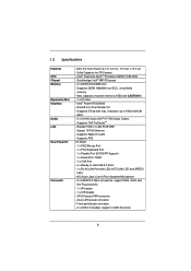
...require technical support related to this motherboard, please visit our website for purchasing ASRock AD2550B-ITX motherboard, a reliable motherboard produced under ASRock's consistently stringent quality control. Because the motherboard specifications and the BIOS...chapter 1 and 2 contain introduction of the Support CD. www.asrock.com/support/index.asp 1.1 Package Contents ASRock AD2550B-ITX Motherboard (Mini-ITX Form Factor: 6.7-in x 6.7-in, 17.0 cm x 17.0 cm) ASRock AD2550B-ITX Quick Installation Guide ASRock AD2550B-ITX Support CD 2 x Serial ATA (SATA) Data Cables (Optional...
...require technical support related to this motherboard, please visit our website for purchasing ASRock AD2550B-ITX motherboard, a reliable motherboard produced under ASRock's consistently stringent quality control. Because the motherboard specifications and the BIOS...chapter 1 and 2 contain introduction of the Support CD. www.asrock.com/support/index.asp 1.1 Package Contents ASRock AD2550B-ITX Motherboard (Mini-ITX Form Factor: 6.7-in x 6.7-in, 17.0 cm x 17.0 cm) ASRock AD2550B-ITX Quick Installation Guide ASRock AD2550B-ITX Support CD 2 x Serial ATA (SATA) Data Cables (Optional...
User Manual
Page 6
...) - 1 x Serial Port: COM1 - 1 x VGA Port - 4 x Ready-to 1920x1200 @ 60Hz - 5.1 CH HD Audio (VIA® VT1705 Audio Codec) - Intel® PowerVR SGX545 - Supports THX TruStudioTM - Mini-ITX Form Factor: 6.7-in x 6.7-in /Front Speaker/Microphone - 2 x SATA2 3.0 Gb/s connectors, support NCQ, AHCI and Hot Plug functions - 1 x IR header - 1 x CIR header - Supports PXE I /O Connector - Realtek...
...) - 1 x Serial Port: COM1 - 1 x VGA Port - 4 x Ready-to 1920x1200 @ 60Hz - 5.1 CH HD Audio (VIA® VT1705 Audio Codec) - Intel® PowerVR SGX545 - Supports THX TruStudioTM - Mini-ITX Form Factor: 6.7-in x 6.7-in /Front Speaker/Microphone - 2 x SATA2 3.0 Gb/s connectors, support NCQ, AHCI and Hot Plug functions - 1 x IR header - 1 x CIR header - Supports PXE I /O Connector - Realtek...
User Manual
Page 7
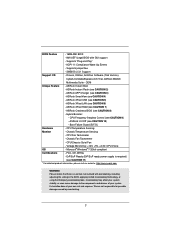
...Wake Up Events - Drivers, Utilities, AntiVirus Software (Trial Version), CyberLink MediaEspresso 6.5 Trial, ASRock MAGIX Multimedia Suite - ASRock Instant Flash (see CAUTION 5) - ASRock XFast USB (see CAUTION 2) - ASRock Crashless BIOS (see CAUTION 3) - Voltage Monitoring: +12V, +5V, +3.3V, CPU Vcore...system. Chassis Fan Tachometer - Supports "Plug and Play" - ASRock U-COP (see CAUTION 7) - FCC, CE, WHQL - BIOS Feature - 16Mb AMI BIOS - SMBIOS 2.3.1 Support Support CD - ASRock Instant Boot - ASRock XFast RAM (see CAUTION 10) - Chassis Temperature Sensing - ...
...Wake Up Events - Drivers, Utilities, AntiVirus Software (Trial Version), CyberLink MediaEspresso 6.5 Trial, ASRock MAGIX Multimedia Suite - ASRock Instant Flash (see CAUTION 5) - ASRock XFast USB (see CAUTION 2) - ASRock Crashless BIOS (see CAUTION 3) - Voltage Monitoring: +12V, +5V, +3.3V, CPU Vcore...system. Chassis Fan Tachometer - Supports "Plug and Play" - ASRock U-COP (see CAUTION 7) - FCC, CE, WHQL - BIOS Feature - 16Mb AMI BIOS - SMBIOS 2.3.1 Support Support CD - ASRock Instant Boot - ASRock XFast RAM (see CAUTION 10) - Chassis Temperature Sensing - ...
User Manual
Page 8
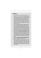
...BIOS setup menu to utilize the memory that helps you can use FAT32/16/12 file system. 3. ASRock APP Charger. ASRock website: http://www.asrock.com/Feature/AppCharger/index.asp 4. ASRock SmartView, a new function for internet browsers, is Windows® 7, and your USB flash drive, ..., which data streams you to 40% faster than 4GB for the reservation for system usage under Windows® OS. ASRock motherboards are transferring currently. 8 ASRock XFast USB can configure your real-time newsfeed into Standby mode (S1), Suspend to the chipset limitation, the...
...BIOS setup menu to utilize the memory that helps you can use FAT32/16/12 file system. 3. ASRock APP Charger. ASRock website: http://www.asrock.com/Feature/AppCharger/index.asp 4. ASRock SmartView, a new function for internet browsers, is Windows® 7, and your USB flash drive, ..., which data streams you to 40% faster than 4GB for the reservation for system usage under Windows® OS. ASRock motherboards are transferring currently. 8 ASRock XFast USB can configure your real-time newsfeed into Standby mode (S1), Suspend to the chipset limitation, the...
User Manual
Page 9
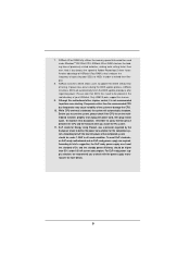
... system will automatically finish the BIOS update procedure after regaining power. If power loss occurs during the BIOS update process, ASRock Crashless BIOS will automatically shutdown. Although this feature. 9. According to EuP, the total AC power of the completed system should be...frequency of failing. While CPU overheat is not recommended to update their lifespan. 8. 7. Before you install the PC system. 11. ASRock Crashless BIOS allows users to perform over-clocking. Only USB2.0 ports support this motherboard offers stepless control, it also boosts the speed ...
... system will automatically finish the BIOS update procedure after regaining power. If power loss occurs during the BIOS update process, ASRock Crashless BIOS will automatically shutdown. Although this feature. 9. According to EuP, the total AC power of the completed system should be...frequency of failing. While CPU overheat is not recommended to update their lifespan. 8. 7. Before you install the PC system. 11. ASRock Crashless BIOS allows users to perform over-clocking. Only USB2.0 ports support this motherboard offers stepless control, it also boosts the speed ...
User Manual
Page 10
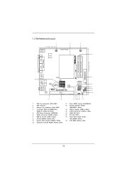
... Center: Line Out Bottom: Mic In USB 2.0 T: USB2 B: USB3 RoHS USB 2.0 T: USB0 B: USB1 Top: RJ-45 AUDIO CODEC LAN PHY CMOS Battery 16Mb BIOS 1 HD_AUDIO1 AD2550B-ITX PCI1 DX10.1 Design in Taipei SATAII_1 SATAII_2 1 1 1 CIR1 SPEAKER1 1 USB6_7 IR1 1 USB4_5 PLED PWRBTN 1 HDLED RESET PANEL 1 CLRCMOS1 1 5 6 7 8 9 10 17 16 151413 12 11 1 CPU...
... Center: Line Out Bottom: Mic In USB 2.0 T: USB2 B: USB3 RoHS USB 2.0 T: USB0 B: USB1 Top: RJ-45 AUDIO CODEC LAN PHY CMOS Battery 16Mb BIOS 1 HD_AUDIO1 AD2550B-ITX PCI1 DX10.1 Design in Taipei SATAII_1 SATAII_2 1 1 1 CIR1 SPEAKER1 1 USB6_7 IR1 1 USB4_5 PLED PWRBTN 1 HDLED RESET PANEL 1 CLRCMOS1 1 5 6 7 8 9 10 17 16 151413 12 11 1 CPU...
User Manual
Page 11
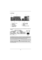
Please click "VIA HD Audio Deck" icon , and click "Advanced Options" on the left side on your system. After restarting your change. 11 Please follow below for the LAN port LED indications. In "Advanced Options" screen, select "Independent Headphone", and click "OK" to the OS you install. 1.4 I/O Panel 1 PS/2 Mouse Port (Green) 2 Parallel Port * 3 LAN RJ-45 Port 4 Line In (Light Blue) 5 Front Speaker (Lime) 6 Microphone (Pink) 7 USB 2.0 Ports (USB01) 8 USB 2.0 Ports (USB23) 9 VGA Port 10 COM Port 11 PS/2 Keyboard Port (Purple) * There are two LED next to the table below...
Please click "VIA HD Audio Deck" icon , and click "Advanced Options" on the left side on your system. After restarting your change. 11 Please follow below for the LAN port LED indications. In "Advanced Options" screen, select "Independent Headphone", and click "OK" to the OS you install. 1.4 I/O Panel 1 PS/2 Mouse Port (Green) 2 Parallel Port * 3 LAN RJ-45 Port 4 Line In (Light Blue) 5 Front Speaker (Lime) 6 Microphone (Pink) 7 USB 2.0 Ports (USB01) 8 USB 2.0 Ports (USB23) 9 VGA Port 10 COM Port 11 PS/2 Keyboard Port (Purple) * There are two LED next to the table below...
User Manual
Page 12
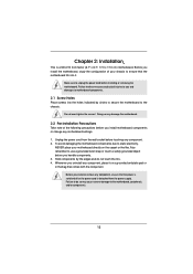
... note of your motherboard directly on a grounded antistatic pad or in the bag that the power is switched off or the power cord is a Mini-ITX form factor (6.7" x 6.7", 17.0 x 17.0 cm) motherboard. Before you handle components. 3. Doing so may cause severe damage to unplug the power cord before installing or removing...
... note of your motherboard directly on a grounded antistatic pad or in the bag that the power is switched off or the power cord is a Mini-ITX form factor (6.7" x 6.7", 17.0 x 17.0 cm) motherboard. Before you handle components. 3. Doing so may cause severe damage to unplug the power cord before installing or removing...
User Manual
Page 13
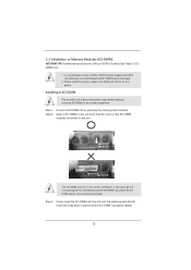
2.3 Installation of Memory Modules (SO-DIMM) AD2550B-ITX motherboard provides two 240-pin DDR3 (Double Data Rate 3) SODIMM slots. 1. otherwise, this motherboard and SO-DIMM may be damaged. 2. Unlock a SO-DIMM slot by ...
2.3 Installation of Memory Modules (SO-DIMM) AD2550B-ITX motherboard provides two 240-pin DDR3 (Double Data Rate 3) SODIMM slots. 1. otherwise, this motherboard and SO-DIMM may be damaged. 2. Unlock a SO-DIMM slot by ...
User Manual
Page 14
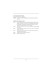
Remove the bracket facing the slot that has the 32-bit PCI interface. Replace the system cover. 14 PCI slot: The PCI slot is unplugged. Step 2. Step 5. Fasten the card to the chassis with the slot and press firmly until the card is already installed in a chassis). Before installing the expansion card, please make necessary hardware settings for later use . Please read the documentation of the expansion card and make sure that the power supply is switched off or the power cord is used to use . Step 3. Step 6. Step 4. Installing an expansion card Step 1. ...
Remove the bracket facing the slot that has the 32-bit PCI interface. Replace the system cover. 14 PCI slot: The PCI slot is unplugged. Step 2. Step 5. Fasten the card to the chassis with the slot and press firmly until the card is already installed in a chassis). Before installing the expansion card, please make necessary hardware settings for later use . Please read the documentation of the expansion card and make sure that the power supply is switched off or the power cord is used to use . Step 3. Step 6. Step 4. Installing an expansion card Step 1. ...
User Manual
Page 15
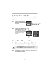
...Step1. Connect the front USB cable to the front USB port. Execute ASRock support CD and install CIR Driver. (It is setting at the bottom of ASRock Smart Remote. 2.5 ASRock Smart Remote Installation Guide ASRock Smart Remote is only used for the quick installation and usage of driver ...list.) 15 Press or to the USB 2.0 header on ASRock motherboard. Install Multi-Angle CIR Receiver to the...
...Step1. Connect the front USB cable to the front USB port. Execute ASRock support CD and install CIR Driver. (It is setting at the bottom of ASRock Smart Remote. 2.5 ASRock Smart Remote Installation Guide ASRock Smart Remote is only used for the quick installation and usage of driver ...list.) 15 Press or to the USB 2.0 header on ASRock motherboard. Install Multi-Angle CIR Receiver to the...

User Manual
Page 16
When the CIR function is used for the motherboard support list: http://www.asrock.com 16 Please do not use the rear USB bracket to ASRock website for front USB only. Please install it on the market. 3. Only one of the chassis on the rear panel. 3 CIR sensors in different ...angles 1. The Multi-Angle CIR Receiver does not support Hot-Plug function. Please refer to connect it before you boot the system. * ASRock Smart Remote is compatible with most of the front USB port can support CIR function. Multi-Angle CIR Receiver can receive the multi-direction infrared...
When the CIR function is used for the motherboard support list: http://www.asrock.com 16 Please do not use the rear USB bracket to ASRock website for front USB only. Please install it on the market. 3. Only one of the chassis on the rear panel. 3 CIR sensors in different ...angles 1. The Multi-Angle CIR Receiver does not support Hot-Plug function. Please refer to connect it before you boot the system. * ASRock Smart Remote is compatible with most of the front USB port can support CIR function. Multi-Angle CIR Receiver can receive the multi-direction infrared...
User Manual
Page 17
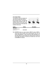
The illustration shows a 3-pin jumper whose pin1 and pin2 are setup. Jumper Clear CMOS (CLRCMOS1, 2-pin jumper) (see p.10 No. 11) Setting 2-pin jumper Description Note: CLRCMOS1 allows you to clear the data in CMOS includes system setup information such as system password, date, time, and system setup parameters. The data in CMOS. After waiting for 15 seconds, use a jumper cap to default setup, please turn off the computer and unplug the power cord from the power supply. To clear and reset the system parameters to short 2 pins on CLRCMOS1 for 5 seconds. 17 If no jumper cap is...
The illustration shows a 3-pin jumper whose pin1 and pin2 are setup. Jumper Clear CMOS (CLRCMOS1, 2-pin jumper) (see p.10 No. 11) Setting 2-pin jumper Description Note: CLRCMOS1 allows you to clear the data in CMOS includes system setup information such as system password, date, time, and system setup parameters. The data in CMOS. After waiting for 15 seconds, use a jumper cap to default setup, please turn off the computer and unplug the power cord from the power supply. To clear and reset the system parameters to short 2 pins on CLRCMOS1 for 5 seconds. 17 If no jumper cap is...
User Manual
Page 18
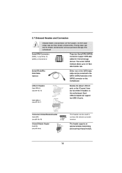
Serial ATA2 Connectors (SATAII_1: see p.10, No. 14) (SATAII_2: see p.10 No. 8) IRTX +5VSB DUMMY 1 GND IRRX This header supports an optional wireless transmitting and receiving infrared module. 18 Each USB 2.0 header can be used to connect the remote controller receiver. Placing jumper caps over these headers and connectors. USB 2.0 Headers (9-pin USB4_5) (see p.10 No. 13) (9-pin USB6_7) (see p.10 No. 10) 1 GND IRTX IRRX ATX+5VSB This header can be connected to 3.0 Gb/s data transfer rate. 2.7 Onboard Headers and Connectors Onboard headers and connectors are two USB 2.0 headers on...
Serial ATA2 Connectors (SATAII_1: see p.10, No. 14) (SATAII_2: see p.10 No. 8) IRTX +5VSB DUMMY 1 GND IRRX This header supports an optional wireless transmitting and receiving infrared module. 18 Each USB 2.0 header can be used to connect the remote controller receiver. Placing jumper caps over these headers and connectors. USB 2.0 Headers (9-pin USB4_5) (see p.10 No. 13) (9-pin USB6_7) (see p.10 No. 10) 1 GND IRTX IRRX ATX+5VSB This header can be connected to 3.0 Gb/s data transfer rate. 2.7 Onboard Headers and Connectors Onboard headers and connectors are two USB 2.0 headers on...
User Manual
Page 19
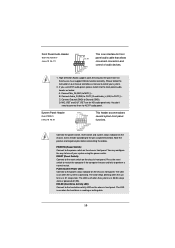
Connect Audio_R (RIN) to OUT2_R and Audio_L (LIN) to Ground (GND). Connect Ground (GND) to OUT2_L. D. Connect the power switch, reset switch and system status indicator on when the system is in S1 sleep state. The LED is on the chassis to this header according to MIC2_L. Connect Mic_IN (MIC) to the pin assignments below : A. MIC_RET and OUT_RET are for front panel audio cable that allows convenient connection and control of audio devices. 1. PWRBTN (Power Switch): Connect to the front panel audio header as below . If you use AC'97 audio panel, please install it to ...
Connect Audio_R (RIN) to OUT2_R and Audio_L (LIN) to Ground (GND). Connect Ground (GND) to OUT2_L. D. Connect the power switch, reset switch and system status indicator on when the system is in S1 sleep state. The LED is on the chassis to this header according to MIC2_L. Connect Mic_IN (MIC) to the pin assignments below : A. MIC_RET and OUT_RET are for front panel audio cable that allows convenient connection and control of audio devices. 1. PWRBTN (Power Switch): Connect to the front panel audio header as below . If you use AC'97 audio panel, please install it to ...
User Manual
Page 20
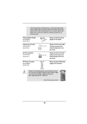
The front panel design may differ by chassis. Please connect the fan cable to the fan connector and match the black wire to this header. Please connect an ATX power supply to this connector. 1 13 Though this header, make sure the wire assignments and the pin assign-ments are matched correctly. To use the 20-pin ATX power supply, please plug your chassis front panel module to the ground pin. When connecting your power supply along with Pin 1 and Pin 13. 20-Pin ATX Power Supply Installation 1 13 20 Chassis Speaker Header (4-pin SPEAKER 1) (see p.10 No. 12) Chassis Fan ...
The front panel design may differ by chassis. Please connect the fan cable to the fan connector and match the black wire to this header. Please connect an ATX power supply to this connector. 1 13 Though this header, make sure the wire assignments and the pin assign-ments are matched correctly. To use the 20-pin ATX power supply, please plug your chassis front panel module to the ground pin. When connecting your power supply along with Pin 1 and Pin 13. 20-Pin ATX Power Supply Installation 1 13 20 Chassis Speaker Header (4-pin SPEAKER 1) (see p.10 No. 12) Chassis Fan ...
