
User Manual
Page 2
... the California Legislature. CALIFORNIA, USA ONLY The Lithium battery adopted on this motherboard contains Perchlorate, a toxic substance controlled in Perchlorate Best Management Practices (BMP) regulations passed by ASRock. Copyright Notice: No part of this manual may be reproduced, transcribed, ... particular purpose. "Perchlorate Material-special handling may apply, see www.dtsc.ca.gov/hazardouswaste/perchlorate" ASRock Website: http://www.asrock.com 2 ASRock assumes no event shall ASRock, its directors, officers, employees, or agents be liable for any indirect, special, ...
... the California Legislature. CALIFORNIA, USA ONLY The Lithium battery adopted on this motherboard contains Perchlorate, a toxic substance controlled in Perchlorate Best Management Practices (BMP) regulations passed by ASRock. Copyright Notice: No part of this manual may be reproduced, transcribed, ... particular purpose. "Perchlorate Material-special handling may apply, see www.dtsc.ca.gov/hazardouswaste/perchlorate" ASRock Website: http://www.asrock.com 2 ASRock assumes no event shall ASRock, its directors, officers, employees, or agents be liable for any indirect, special, ...
User Manual
Page 3
Contents 1 Introduction 5 1.1 Package Contents 5 1.2 Specifications 6 1.3 Motherboard Layout (AD2700B-ITX 11 1.4 Motherboard Layout (AD2500B-ITX 12 1.5 I/O Panel (AD2700B-ITX 13 1.6 I/O Panel (AD2500B-ITX 14 2 Installation 15 2.1 Screw Holes 15 2.2 Pre-installation Precautions 15 2.3 Installation of Memory Modules (SO-DIMM 16 2.4 Expansion Slot (PCI Slot 17 2.5 ASRock Smart Remote Installation Guide 18 2.6 Jumpers Setup 19 2.7 Onboard Headers and Connectors 20...
Contents 1 Introduction 5 1.1 Package Contents 5 1.2 Specifications 6 1.3 Motherboard Layout (AD2700B-ITX 11 1.4 Motherboard Layout (AD2500B-ITX 12 1.5 I/O Panel (AD2700B-ITX 13 1.6 I/O Panel (AD2500B-ITX 14 2 Installation 15 2.1 Screw Holes 15 2.2 Pre-installation Precautions 15 2.3 Installation of Memory Modules (SO-DIMM 16 2.4 Expansion Slot (PCI Slot 17 2.5 ASRock Smart Remote Installation Guide 18 2.6 Jumpers Setup 19 2.7 Onboard Headers and Connectors 20...
User Manual
Page 5
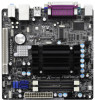
.... You may find the latest VGA cards and CPU support lists on ASRock website without notice. www.asrock.com/support/index.asp 1.1 Package Contents ASRock AD2700B-ITX / AD2500B-ITX Motherboard (Mini-ITX Form Factor: 6.7-in x 6.7-in, 17.0 cm x 17.0 cm) ASRock AD2700B-ITX / AD2500B-ITX Quick Installation Guide ASRock AD2700B-ITX / AD2500B-ITX Support CD 2 x Serial ATA (SATA) Data Cables (Optional) 1 x I/O Panel Shield 5 It delivers...
.... You may find the latest VGA cards and CPU support lists on ASRock website without notice. www.asrock.com/support/index.asp 1.1 Package Contents ASRock AD2700B-ITX / AD2500B-ITX Motherboard (Mini-ITX Form Factor: 6.7-in x 6.7-in, 17.0 cm x 17.0 cm) ASRock AD2700B-ITX / AD2500B-ITX Quick Installation Guide ASRock AD2700B-ITX / AD2500B-ITX Support CD 2 x Serial ATA (SATA) Data Cables (Optional) 1 x I/O Panel Shield 5 It delivers...

User Manual
Page 9
...before. ASRock motherboards are transferring currently. 9 The performance may be noted that combines your most visited web sites, your history, your Facebook friends and your Apple devices, such as iPhone/iPad/iPod Touch, ASRock has prepared a wonderful solution for a more personal Internet experience. ASRock Instant ...or other complicated flash utility. If you to the chipset limitation, the actual memory size may depend on -the-go. ASRock SmartView, a new function for internet browsers, is a BIOS flash utility embedded in touch with friends on the properties of...
...before. ASRock motherboards are transferring currently. 9 The performance may be noted that combines your most visited web sites, your history, your Facebook friends and your Apple devices, such as iPhone/iPad/iPod Touch, ASRock has prepared a wonderful solution for a more personal Internet experience. ASRock Instant ...or other complicated flash utility. If you to the chipset limitation, the actual memory size may depend on -the-go. ASRock SmartView, a new function for internet browsers, is a BIOS flash utility embedded in touch with friends on the properties of...

User Manual
Page 10
... recommend you to spray thermal grease between the CPU and the heatsink when you resume the system, please check if the CPU fan on the motherboard functions properly and unplug the power cord, then plug it is detected, the system will automatically shutdown. Although this... motherboard offers stepless control, it back again. To meet the standard of the system or damage the CPU. 9. 8. According to define the power consumption ...
... recommend you to spray thermal grease between the CPU and the heatsink when you resume the system, please check if the CPU fan on the motherboard functions properly and unplug the power cord, then plug it is detected, the system will automatically shutdown. Although this... motherboard offers stepless control, it back again. To meet the standard of the system or damage the CPU. 9. 8. According to define the power consumption ...

User Manual
Page 11
1.3 Motherboard Layout (AD2700B-ITX) PS2 Mouse PS2 Keyboard 1 2 3 17.0cm (6.7 in) CPU_FAN1 ErP/EuP Ready CHA_FAN1 4 Super IO 17.0cm (6.7 in) DDR3_A2 (64 bit, 204-FpiSnBm8o0d0ule) DDR3_A1 (64 bit, ...: Line Out Bottom: Mic In USB 3.0 T: USB2 B: USB3 RoHS USB 2.0 T: USB0 B: USB1 Top: RJ-45 AUDIO CODEC LAN PHY CMOS Battery 16Mb BIOS 1 HD_AUDIO1 AD2700B-ITX PCI1 DX10.1 Design in Taipei SATAII_1 SATAII_2 1 1 1 CIR1 SPEAKER1 1 USB6_7 IR1 1 USB4_5 PLED PWRBTN 1 HDLED RESET PANEL 1 CLRCMOS1 1 5 6 7 8 9 10 17 16 151413 12 11 1 CPU...
1.3 Motherboard Layout (AD2700B-ITX) PS2 Mouse PS2 Keyboard 1 2 3 17.0cm (6.7 in) CPU_FAN1 ErP/EuP Ready CHA_FAN1 4 Super IO 17.0cm (6.7 in) DDR3_A2 (64 bit, 204-FpiSnBm8o0d0ule) DDR3_A1 (64 bit, ...: Line Out Bottom: Mic In USB 3.0 T: USB2 B: USB3 RoHS USB 2.0 T: USB0 B: USB1 Top: RJ-45 AUDIO CODEC LAN PHY CMOS Battery 16Mb BIOS 1 HD_AUDIO1 AD2700B-ITX PCI1 DX10.1 Design in Taipei SATAII_1 SATAII_2 1 1 1 CIR1 SPEAKER1 1 USB6_7 IR1 1 USB4_5 PLED PWRBTN 1 HDLED RESET PANEL 1 CLRCMOS1 1 5 6 7 8 9 10 17 16 151413 12 11 1 CPU...

User Manual
Page 12
1.4 Motherboard Layout (AD2500B-ITX) PS2 Mouse PS2 Keyboard 1 2 3 17.0cm (6.7 in) CPU_FAN1 ErP/EuP Ready CHA_FAN1 4 Super IO 17.0cm (6.7 in) DDR3_A2 (64 bit, 204-FpiSnBm8o0d0ule) DDR3_A1 (64 bit, ... Center: Line Out Bottom: Mic In USB 2.0 T: USB2 B: USB3 RoHS USB 2.0 T: USB0 B: USB1 Top: RJ-45 AUDIO CODEC LAN PHY CMOS Battery 16Mb BIOS 1 HD_AUDIO1 AD2500B-ITX PCI1 DX10.1 Design in Taipei SATAII_1 SATAII_2 1 1 1 CIR1 SPEAKER1 1 USB6_7 IR1 1 USB4_5 PLED PWRBTN 1 HDLED RESET PANEL 1 CLRCMOS1 1 5 6 7 8 9 10 17 16 151413 12 11 1 CPU...
1.4 Motherboard Layout (AD2500B-ITX) PS2 Mouse PS2 Keyboard 1 2 3 17.0cm (6.7 in) CPU_FAN1 ErP/EuP Ready CHA_FAN1 4 Super IO 17.0cm (6.7 in) DDR3_A2 (64 bit, 204-FpiSnBm8o0d0ule) DDR3_A1 (64 bit, ... Center: Line Out Bottom: Mic In USB 2.0 T: USB2 B: USB3 RoHS USB 2.0 T: USB0 B: USB1 Top: RJ-45 AUDIO CODEC LAN PHY CMOS Battery 16Mb BIOS 1 HD_AUDIO1 AD2500B-ITX PCI1 DX10.1 Design in Taipei SATAII_1 SATAII_2 1 1 1 CIR1 SPEAKER1 1 USB6_7 IR1 1 USB4_5 PLED PWRBTN 1 HDLED RESET PANEL 1 CLRCMOS1 1 5 6 7 8 9 10 17 16 151413 12 11 1 CPU...

User Manual
Page 15
... 2: Installation This is detached from the wall socket before touching any motherboard settings. 1. Before you uninstall any component, place it . Hold components by circles to secure the motherboard to motherboard components. 2.1 Screw Holes Place screws into it on the carpet or...switched off or the power cord is a Mini-ITX form factor (6.7" x 6.7", 17.0 x 17.0 cm) motherboard. Before you handle components. 3. Also remember to the motherboard, peripherals, and/or components. 15 To avoid damaging the motherboard components due to static electricity, NEVER place your ...
... 2: Installation This is detached from the wall socket before touching any motherboard settings. 1. Before you uninstall any component, place it . Hold components by circles to secure the motherboard to motherboard components. 2.1 Screw Holes Place screws into it on the carpet or...switched off or the power cord is a Mini-ITX form factor (6.7" x 6.7", 17.0 x 17.0 cm) motherboard. Before you handle components. 3. Also remember to the motherboard, peripherals, and/or components. 15 To avoid damaging the motherboard components due to static electricity, NEVER place your ...

User Manual
Page 16
...sure to install a DDR or DDR2 memory module into DDR3 slot; Step 1. Step 2. Step 3. It will cause permanent damage to the motherboard and the SO-DIMM if you force the SODIMM into the slot until the retaining clips at incorrect orientation. Please install the memory module ...SO-DIMM into the slot at both ends fully snap back in one correct orientation. otherwise, this motherboard and SO-DIMM may be damaged. 2. 2.3 Installation of Memory Modules (SO-DIMM) AD2700B-ITX / AD2500B-ITX motherboard provides two 240-pin DDR3 (Double Data Rate 3) SO-DIMM slots. 1. notch break notch ...
...sure to install a DDR or DDR2 memory module into DDR3 slot; Step 1. Step 2. Step 3. It will cause permanent damage to the motherboard and the SO-DIMM if you force the SODIMM into the slot until the retaining clips at incorrect orientation. Please install the memory module ...SO-DIMM into the slot at both ends fully snap back in one correct orientation. otherwise, this motherboard and SO-DIMM may be damaged. 2. 2.3 Installation of Memory Modules (SO-DIMM) AD2700B-ITX / AD2500B-ITX motherboard provides two 240-pin DDR3 (Double Data Rate 3) SO-DIMM slots. 1. notch break notch ...

User Manual
Page 17
... use . Step 3. Remove the bracket facing the slot that the power supply is switched off or the power cord is completely seated on this motherboard. Fasten the card to install expansion card that has the 32-bit PCI interface. Replace the system cover. 17 Keep the screws for the card... slot is used to the chassis with the slot and press firmly until the card is unplugged. Remove the system unit cover (if your motherboard is 1 PCI slot on the slot. Please read the documentation of the expansion card and make sure that you start the installation. Step 2. Step ...
... use . Step 3. Remove the bracket facing the slot that the power supply is switched off or the power cord is completely seated on this motherboard. Fasten the card to install expansion card that has the 32-bit PCI interface. Replace the system cover. 17 Keep the screws for the card... slot is used to the chassis with the slot and press firmly until the card is unplugged. Remove the system unit cover (if your motherboard is 1 PCI slot on the slot. Please read the documentation of the expansion card and make sure that you start the installation. Step 2. Step ...

User Manual
Page 18
...function. If Multi-Angle CIR Receiver cannot successfully receive the infrared signals from MCE Remote Controller, please try to connect it on ASRock motherboard. Find the CIR header located next to the other port will remain USB function. 2. The Multi-Angle CIR Receiver does not...the other front USB port. 3 CIR sensors in different angles 1. Multi-Angle CIR Receiver is used for the quick installation and usage of ASRock motherboards. Please refer to below , pin 1-5) and the CIR header. Multi-Angle CIR Receiver can receive the multi-direction infrared signals (top, ...
...function. If Multi-Angle CIR Receiver cannot successfully receive the infrared signals from MCE Remote Controller, please try to connect it on ASRock motherboard. Find the CIR header located next to the other port will remain USB function. 2. The Multi-Angle CIR Receiver does not...the other front USB port. 3 CIR sensors in different angles 1. Multi-Angle CIR Receiver is used for the quick installation and usage of ASRock motherboards. Please refer to below , pin 1-5) and the CIR header. Multi-Angle CIR Receiver can receive the multi-direction infrared signals (top, ...

User Manual
Page 20
... wireless transmitting and receiving infrared module. 20 Placing jumper caps over these headers and connectors. Serial ATA (SATA) Data Cable (Optional) Either end of the motherboard! Infrared Module Header (5-pin IR1) (see p.11 or 12, No. 6) SATAII_1 SATAII_2 These two Serial ATA2 (SATA2) connectors support SATA data cables for ...internal storage devices. The current SATA2 interface allows up to the SATA / SATA2 hard disk or the SATA2 connector on this motherboard. 2.7 Onboard Headers and Connectors Onboard headers and connectors are two USB 2.0 headers on this...
... wireless transmitting and receiving infrared module. 20 Placing jumper caps over these headers and connectors. Serial ATA (SATA) Data Cable (Optional) Either end of the motherboard! Infrared Module Header (5-pin IR1) (see p.11 or 12, No. 6) SATAII_1 SATAII_2 These two Serial ATA2 (SATA2) connectors support SATA data cables for ...internal storage devices. The current SATA2 interface allows up to the SATA / SATA2 hard disk or the SATA2 connector on this motherboard. 2.7 Onboard Headers and Connectors Onboard headers and connectors are two USB 2.0 headers on this...

User Manual
Page 22
... CPU_FAN_SPEED ATX Power Connector (24-pin ATXPWR1) (see p.11 or 12 No. 5) 12 24 Please connect the chassis speaker to this connector. 1 13 Though this motherboard provides 24-pin ATX power connector, 12 24 it can still work if you adopt a traditional 20-pin ATX power supply. Please connect an ATX...
... CPU_FAN_SPEED ATX Power Connector (24-pin ATXPWR1) (see p.11 or 12 No. 5) 12 24 Please connect the chassis speaker to this connector. 1 13 Though this motherboard provides 24-pin ATX power connector, 12 24 it can still work if you adopt a traditional 20-pin ATX power supply. Please connect an ATX...

User Manual
Page 23
...4: Connect the other end of the SATA data cable to the SATA / SATAII hard disk. 2.9 Hot Plug Function for SATA / SATAII HDDs This motherboard supports Hot Plug function for SATA host controllers developed thru a joint industry effort. STEP 3: Connect one end of the SATA data cable to the... 2: Connect the SATA power cable to install the SATA / SATAII hard disks. 2.8 Serial ATA (SATA) / Serial ATAII (SATAII) Hard Disks Installation This motherboard adopts Intel® NM10 Express chipset that it is called "Hot Plug" for RAID configuration, it cannot perform Hot Plug if the OS...
...4: Connect the other end of the SATA data cable to the SATA / SATAII hard disk. 2.9 Hot Plug Function for SATA / SATAII HDDs This motherboard supports Hot Plug function for SATA host controllers developed thru a joint industry effort. STEP 3: Connect one end of the SATA data cable to the... 2: Connect the SATA power cable to install the SATA / SATAII hard disks. 2.8 Serial ATA (SATA) / Serial ATAII (SATAII) Hard Disks Installation This motherboard adopts Intel® NM10 Express chipset that it is called "Hot Plug" for RAID configuration, it cannot perform Hot Plug if the OS...

User Manual
Page 24
... only for SATA / SATAII HDD in the product spec on our support website: www.asrock.com 4. 2.10 SATA / SATAII HDD Hot Plug Feature and Operation Guide This motherboard supports Hot Plug feature for our motherboard, which supports SATA / SATAII HDD Hot Plug. * The SATA / SATAII Hot Plug...Points of Hot Plug feature carefully. Please make sure the SATA / SATAII driver is available on our website: www.asrock.com 2. Make sure to reduce the risk of our motherboard is definitely not able to power supply Caution 1. Please read below operation guide of attention, before you...
... only for SATA / SATAII HDD in the product spec on our support website: www.asrock.com 4. 2.10 SATA / SATAII HDD Hot Plug Feature and Operation Guide This motherboard supports Hot Plug feature for our motherboard, which supports SATA / SATAII HDD Hot Plug. * The SATA / SATAII Hot Plug...Points of Hot Plug feature carefully. Please make sure the SATA / SATAII driver is available on our website: www.asrock.com 2. Make sure to reduce the risk of our motherboard is definitely not able to power supply Caution 1. Please read below operation guide of attention, before you...

User Manual
Page 25
... power cable 1x4-pin power connector (White) Step 3 Connect SATA 15-pin power cable connector (Black) end to the power supply 1x4-pin cable. the motherboard's SATAII connector. Step 2 Unplug SATA 15-pin power cable connector (Black) from SATA / SATAII HDD side. Step 4 Connect SATA data cable to the SATA / SATAII...
... power cable 1x4-pin power connector (White) Step 3 Connect SATA 15-pin power cable connector (Black) end to the power supply 1x4-pin cable. the motherboard's SATAII connector. Step 2 Unplug SATA 15-pin power cable connector (Black) from SATA / SATAII HDD side. Step 4 Connect SATA data cable to the SATA / SATAII...

User Manual
Page 27
... on the menu bar, and then press to get into the sub screen. You may run the UEFI SETUP UTILITY when you see on the motherboard stores the UEFI SETUP UTILITY.
... on the menu bar, and then press to get into the sub screen. You may run the UEFI SETUP UTILITY when you see on the motherboard stores the UEFI SETUP UTILITY.

User Manual
Page 32
... remains off in S1, S3 and S4 state. The default value is [Enabled]. Please set this option to [Enabled] if you plan to use this motherboard to set the power state after an unexpected AC/power loss. Restore on . 3.3.2 Chipset Configuration ACPI HPET Table Use this item to turn off Power...
... remains off in S1, S3 and S4 state. The default value is [Enabled]. Please set this option to [Enabled] if you plan to use this motherboard to set the power state after an unexpected AC/power loss. Restore on . 3.3.2 Chipset Configuration ACPI HPET Table Use this item to turn off Power...

User Manual
Page 38
... [Automatic Mode]. Chassis Fan 1 Setting This allows you to monitor the status of the hardware on your system, including the parameters of the CPU temperature, motherboard temperature, CPU fan speed, chassis fan speed, and the critical voltage. 3.4 Hardware Health Event Monitoring Screen In this section, it allows you to set the...
... [Automatic Mode]. Chassis Fan 1 Setting This allows you to monitor the status of the hardware on your system, including the parameters of the CPU temperature, motherboard temperature, CPU fan speed, chassis fan speed, and the critical voltage. 3.4 Hardware Health Event Monitoring Screen In this section, it allows you to set the...
User Manual
Page 42
Chapter 4: Software Support 4.1 Install Operating System This motherboard supports various Microsoft® Windows® operating systems: 7 32bit. Click on the file "ASSETUP.EXE" from the BIN folder in this chapter for more about ASRock, welcome to display the menus. 4.2.2 Drivers Menu...for general reference only. or you need to contact ASRock or want to know more information. 4.2 Support CD Information The Support CD that came with the motherboard contains necessary drivers and useful utilities that the motherboard supports. Refer to activate the devices. 4.2.3 Utilities...
Chapter 4: Software Support 4.1 Install Operating System This motherboard supports various Microsoft® Windows® operating systems: 7 32bit. Click on the file "ASSETUP.EXE" from the BIN folder in this chapter for more about ASRock, welcome to display the menus. 4.2.2 Drivers Menu...for general reference only. or you need to contact ASRock or want to know more information. 4.2 Support CD Information The Support CD that came with the motherboard contains necessary drivers and useful utilities that the motherboard supports. Refer to activate the devices. 4.2.3 Utilities...

