User Manual
Page 3
... Guide 18 2.6 Jumpers Setup 19 2.7 Onboard Headers and Connectors 20 2.8 Serial ATA (SATA) / Serial ATA2 (SATA2) Hard Disks Installation 23 2.9 Hot Plug and Hot Swap Functions for SATA / SATA2 HDDs 23 2.10 SATA / SATA2 HDD Hot Plug Feature and Operation Guide 24 2.11 Driver Installation Guide 26 2.12 Installing Windows® 7 on SATA / SATAII HDDs ........ 26 3 UEFI SETUP UTILITY 27 3.1 Introduction 27 3.1.1 UEFI Menu Bar 27 3.1.2 Navigation Keys 28 3.2 Main Screen 28 3.3 Advanced Screen 30 3.3.1 CPU Configuration 31 3.3.2 Chipset Configuration 32 3.3.3 Storage...
... Guide 18 2.6 Jumpers Setup 19 2.7 Onboard Headers and Connectors 20 2.8 Serial ATA (SATA) / Serial ATA2 (SATA2) Hard Disks Installation 23 2.9 Hot Plug and Hot Swap Functions for SATA / SATA2 HDDs 23 2.10 SATA / SATA2 HDD Hot Plug Feature and Operation Guide 24 2.11 Driver Installation Guide 26 2.12 Installing Windows® 7 on SATA / SATAII HDDs ........ 26 3 UEFI SETUP UTILITY 27 3.1 Introduction 27 3.1.1 UEFI Menu Bar 27 3.1.2 Navigation Keys 28 3.2 Main Screen 28 3.3 Advanced Screen 30 3.3.1 CPU Configuration 31 3.3.2 Chipset Configuration 32 3.3.3 Storage...

User Manual
Page 7
...Speaker/Microphone - 2 x USB 3.0 ports by ASMedia ASM1042, support USB 1.0/2.0/3.0 up to -Use USB 2.0 Ports - 1 x RJ-45 LAN Port with LED (ACT/LINK LED and SPEED LED) - HD Audio Jack: Line in /Front Speaker/Microphone I /O (AD2500B-ITX) USB 3.0 (AD2700B-ITX) Connector BIOS Feature Support CD Unique Feature - 1 x RJ-45 LAN Port with GUI support - Trial; Supports "Plug and Play" - ASRock APP Charger (see CAUTION 6) - ASRock XFast LAN (see CAUTION 7) 7 AMI UEFI Legal BIOS with LED (ACT/LINK LED and SPEED LED) - CPU/Chassis FAN connector - 24 pin ATX power connector - ACPI...
...Speaker/Microphone - 2 x USB 3.0 ports by ASMedia ASM1042, support USB 1.0/2.0/3.0 up to -Use USB 2.0 Ports - 1 x RJ-45 LAN Port with LED (ACT/LINK LED and SPEED LED) - HD Audio Jack: Line in /Front Speaker/Microphone I /O (AD2500B-ITX) USB 3.0 (AD2700B-ITX) Connector BIOS Feature Support CD Unique Feature - 1 x RJ-45 LAN Port with GUI support - Trial; Supports "Plug and Play" - ASRock APP Charger (see CAUTION 6) - ASRock XFast LAN (see CAUTION 7) 7 AMI UEFI Legal BIOS with LED (ACT/LINK LED and SPEED LED) - CPU/Chassis FAN connector - 24 pin ATX power connector - ACPI...

User Manual
Page 9
... into the BIOS setup menu to RAM (S3), hibernation mode (S4) or power off (S5). Real-Time Analysis of the device. 7. CAUTION! 1. This convenient BIOS update tool allows you can easily recognize which includes the benefits listed below. Traffic Shaping: You can boost USB storage device performance. If you keep in games. ASRock motherboards are transferring currently. 9 ASRock XFast LAN provides a faster internet access, which...
... into the BIOS setup menu to RAM (S3), hibernation mode (S4) or power off (S5). Real-Time Analysis of the device. 7. CAUTION! 1. This convenient BIOS update tool allows you can easily recognize which includes the benefits listed below. Traffic Shaping: You can boost USB storage device performance. If you keep in games. ASRock motherboards are transferring currently. 9 ASRock XFast LAN provides a faster internet access, which...

User Manual
Page 11
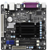
...CPU Fan Connector (CPU_FAN1) 2 CPU Heatsink 3 Chassis Fan Connector (CHA_FAN1) 4 2 x 240-pin DDR3 SO-DIMM Slots (DDR3_A1, DDR3_A2, Black) 5 ATX Power Connector (ATXPWR1) 6 SATA2 Connector (SATAII_2, Blue) 7 USB 2.0 Header (USB6_7, Blue) 8 Infrared Module Header (IR1) 9 System Panel Header (PANEL1, White) 10 Consumer Infrared Module Header (CIR1) 11 Clear CMOS Jumper (CLRCMOS1) 12 Chassis Speaker Header (SPEAKER 1, White) 13 USB 2.0 Header (USB4_5, Blue) 14 SATA2 Connector (SATAII_1, Blue) 15 16Mb SPI Flash 16 PCI Slot (PCI1) 17 Front Panel Audio Header (HD_AUDIO1, White) 18 Intel NM10 Express...
...CPU Fan Connector (CPU_FAN1) 2 CPU Heatsink 3 Chassis Fan Connector (CHA_FAN1) 4 2 x 240-pin DDR3 SO-DIMM Slots (DDR3_A1, DDR3_A2, Black) 5 ATX Power Connector (ATXPWR1) 6 SATA2 Connector (SATAII_2, Blue) 7 USB 2.0 Header (USB6_7, Blue) 8 Infrared Module Header (IR1) 9 System Panel Header (PANEL1, White) 10 Consumer Infrared Module Header (CIR1) 11 Clear CMOS Jumper (CLRCMOS1) 12 Chassis Speaker Header (SPEAKER 1, White) 13 USB 2.0 Header (USB4_5, Blue) 14 SATA2 Connector (SATAII_1, Blue) 15 16Mb SPI Flash 16 PCI Slot (PCI1) 17 Front Panel Audio Header (HD_AUDIO1, White) 18 Intel NM10 Express...

User Manual
Page 12
...CPU Fan Connector (CPU_FAN1) 2 CPU Heatsink 3 Chassis Fan Connector (CHA_FAN1) 4 2 x 240-pin DDR3 SO-DIMM Slots (DDR3_A1, DDR3_A2, Black) 5 ATX Power Connector (ATXPWR1) 6 SATA2 Connector (SATAII_2, Blue) 7 USB 2.0 Header (USB6_7, Blue) 8 Infrared Module Header (IR1) 9 System Panel Header (PANEL1, White) 10 Consumer Infrared Module Header (CIR1) 11 Clear CMOS Jumper (CLRCMOS1) 12 Chassis Speaker Header (SPEAKER 1, White) 13 USB 2.0 Header (USB4_5, Blue) 14 SATA2 Connector (SATAII_1, Blue) 15 16Mb SPI Flash 16 PCI Slot (PCI1) 17 Front Panel Audio Header (HD_AUDIO1, White) 18 Intel NM10 Express...
...CPU Fan Connector (CPU_FAN1) 2 CPU Heatsink 3 Chassis Fan Connector (CHA_FAN1) 4 2 x 240-pin DDR3 SO-DIMM Slots (DDR3_A1, DDR3_A2, Black) 5 ATX Power Connector (ATXPWR1) 6 SATA2 Connector (SATAII_2, Blue) 7 USB 2.0 Header (USB6_7, Blue) 8 Infrared Module Header (IR1) 9 System Panel Header (PANEL1, White) 10 Consumer Infrared Module Header (CIR1) 11 Clear CMOS Jumper (CLRCMOS1) 12 Chassis Speaker Header (SPEAKER 1, White) 13 USB 2.0 Header (USB4_5, Blue) 14 SATA2 Connector (SATAII_1, Blue) 15 16Mb SPI Flash 16 PCI Slot (PCI1) 17 Front Panel Audio Header (HD_AUDIO1, White) 18 Intel NM10 Express...

User Manual
Page 20
... header can be connected to connect the remote controller receiver. Infrared Module Header (5-pin IR1) (see p.11 or 12, No. 6) SATAII_1 SATAII_2 These two Serial ATA2 (SATA2) connectors support SATA data cables for internal storage devices. Do NOT place jumper caps over the headers and connectors will cause permanent damage of the SATA data cable can support two USB 2.0 ports. Serial ATA (SATA) Data Cable (Optional) Either end of the motherboard! Each USB 2.0 header can be used to the SATA / SATA2 hard disk...
... header can be connected to connect the remote controller receiver. Infrared Module Header (5-pin IR1) (see p.11 or 12, No. 6) SATAII_1 SATAII_2 These two Serial ATA2 (SATA2) connectors support SATA data cables for internal storage devices. Do NOT place jumper caps over the headers and connectors will cause permanent damage of the SATA data cable can support two USB 2.0 ports. Serial ATA (SATA) Data Cable (Optional) Either end of the motherboard! Each USB 2.0 header can be used to the SATA / SATA2 hard disk...

User Manual
Page 22
... connecting your power supply along with Pin 1 and Pin 13. 20-Pin ATX Power Supply Installation 1 13 22 Please connect an ATX power supply to this connector. 1 13 Though this header. A front panel module mainly consists of power switch, reset switch, power LED, hard drive activity LED, speaker and etc. The front panel design may differ by chassis. Please connect the CPU fan cable to the connector and match the black wire to the ground pin. To use the 20-pin ATX power supply, please plug your chassis front panel module to this motherboard provides 24-pin ATX power...
... connecting your power supply along with Pin 1 and Pin 13. 20-Pin ATX Power Supply Installation 1 13 22 Please connect an ATX power supply to this connector. 1 13 Though this header. A front panel module mainly consists of power switch, reset switch, power LED, hard drive activity LED, speaker and etc. The front panel design may differ by chassis. Please connect the CPU fan cable to the connector and match the black wire to the ground pin. To use the 20-pin ATX power supply, please plug your chassis front panel module to this motherboard provides 24-pin ATX power...

User Manual
Page 24
... in AHCI mode. The latest SATA / SATAII driver is definitely not able to power supply Caution 1. Before you process the Hot Plug: 1. Even some SATA / SATAII HDDs provide both SATA 15-pin power connector and IDE 1x4-pin conventional power connector interfaces, the IDE 1x4-pin conventional power connector interface is available on our website: www.asrock.com 2. The SATA / SATAII HDD, which are from your SATA / SATAII HDD can support Hot Plug function from our motherboard...
... in AHCI mode. The latest SATA / SATAII driver is definitely not able to power supply Caution 1. Before you process the Hot Plug: 1. Even some SATA / SATAII HDDs provide both SATA 15-pin power connector and IDE 1x4-pin conventional power connector interfaces, the IDE 1x4-pin conventional power connector interface is available on our website: www.asrock.com 2. The SATA / SATAII HDD, which are from your SATA / SATAII HDD can support Hot Plug function from our motherboard...

User Manual
Page 26
... Installing Windows® 7 on SATA / SATAII HDDs If you install can be auto-detected and listed on your optical drive first. Storage Configuration. Set the option "SATA Mode" to [IDE]. Enter UEFI SETUP UTILITY Advanced screen B. Using SATA / SATAII HDDs with NCQ function STEP 1: Set up UEFI. Enter UEFI SETUP UTILITY Advanced screen B. Therefore, the drivers you want to install Windows® 7 OS on the support CD driver page. STEP 2: Install Windows® 7 OS on your system. Storage Configuration. 26 A. Set the option "SATA Mode" to [AHCI...
... Installing Windows® 7 on SATA / SATAII HDDs If you install can be auto-detected and listed on your optical drive first. Storage Configuration. Set the option "SATA Mode" to [IDE]. Enter UEFI SETUP UTILITY Advanced screen B. Using SATA / SATAII HDDs with NCQ function STEP 1: Set up UEFI. Enter UEFI SETUP UTILITY Advanced screen B. Therefore, the drivers you want to install Windows® 7 OS on the support CD driver page. STEP 2: Install Windows® 7 OS on your system. Storage Configuration. 26 A. Set the option "SATA Mode" to [AHCI...

User Manual
Page 27
... motherboard stores the UEFI SETUP UTILITY. You may not exactly match what you wish to get into the sub screen. Because the UEFI software is constantly being updated, the following selections: Main To set up the system time/date information OC Tweaker To set up overclocking features Advanced To set up the advanced UEFI features H/W Monitor To display current hardware status Boot To set up the default system device to locate...
... motherboard stores the UEFI SETUP UTILITY. You may not exactly match what you wish to get into the sub screen. Because the UEFI software is constantly being updated, the following selections: Main To set up the system time/date information OC Tweaker To set up overclocking features Advanced To set up the advanced UEFI features H/W Monitor To display current hardware status Boot To set up the default system device to locate...

User Manual
Page 32
.... Onboard HD Audio Select [Auto], [Enabled] or [Disabled] for the onboard HD Audio Front Panel. If [Power On] is [Enabled]. 3.3.2 Chipset Configuration ACPI HPET Table Use this option to [Enabled] if you to enable or disable the "Onboard LAN" feature. The default value is selected, the AC/power resumes and the system starts to boot up when the power recovers. Front Panel Select [Auto] or [Disabled] for the onboard HD Audio feature. Restore on . The keyboard LED will also be disabled when PCI Sound Card is power...
.... Onboard HD Audio Select [Auto], [Enabled] or [Disabled] for the onboard HD Audio Front Panel. If [Power On] is [Enabled]. 3.3.2 Chipset Configuration ACPI HPET Table Use this option to [Enabled] if you to enable or disable the "Onboard LAN" feature. The default value is selected, the AC/power resumes and the system starts to boot up when the power recovers. Front Panel Select [Auto] or [Disabled] for the onboard HD Audio feature. Restore on . The keyboard LED will also be disabled when PCI Sound Card is power...

User Manual
Page 36
... or disable the use under UEFI setup and Windows / Linux OS. Please refer to below descriptions for legacy USB. [Auto] - Enables support for the details of USB 3.0 controller. USB 3.0 Controller Use this option to enable or disable legacy support for USB 3.0 devices. There are connected. [Disabled] - The default value is [Disabled]. 36 Legacy USB Support Use this item to enable or disable the use only under legacy OS and UEFI setup when [Disabled] is recommended to select [Disabled] to enter OS. [UEFI Setup Only] - 3.3.6 USB Configuration USB 2.0 Controller Use this...
... or disable the use under UEFI setup and Windows / Linux OS. Please refer to below descriptions for legacy USB. [Auto] - Enables support for the details of USB 3.0 controller. USB 3.0 Controller Use this option to enable or disable legacy support for USB 3.0 devices. There are connected. [Disabled] - The default value is [Disabled]. 36 Legacy USB Support Use this item to enable or disable the use only under legacy OS and UEFI setup when [Disabled] is recommended to select [Disabled] to enter OS. [UEFI Setup Only] - 3.3.6 USB Configuration USB 2.0 Controller Use this...
User Manual
Page 42
... the installation wizard to install it. 4.2.4 Contact Information If you may contact your computer. Chapter 4: Software Support 4.1 Install Operating System This motherboard supports various Microsoft® Windows® operating systems: 7 32bit. Because motherboard settings and hardware options vary, use the setup procedures in your dealer for general reference only. Please install the necessary drivers to display the menus. 4.2.2 Drivers Menu The Drivers Menu shows the available devices drivers if the system detects installed devices.
... the installation wizard to install it. 4.2.4 Contact Information If you may contact your computer. Chapter 4: Software Support 4.1 Install Operating System This motherboard supports various Microsoft® Windows® operating systems: 7 32bit. Because motherboard settings and hardware options vary, use the setup procedures in your dealer for general reference only. Please install the necessary drivers to display the menus. 4.2.2 Drivers Menu The Drivers Menu shows the available devices drivers if the system detects installed devices.

Quick Installation Guide
Page 2
...) 2 CPU Heatsink 3 Chassis Fan Connector (CHA_FAN1) 4 2 x 240-pin DDR3 SO-DIMM Slots (DDR3_A1, DDR3_A2, Black) 5 ATX Power Connector (ATXPWR1) 6 SATA2 Connector (SATAII_2, Blue) 7 USB 2.0 Header (USB6_7, Blue) 8 Infrared Module Header (IR1) 9 System Panel Header (PANEL1, White) 10 Consumer Infrared Module Header (CIR1) 11 Clear CMOS Jumper (CLRCMOS1) 12 Chassis Speaker Header (SPEAKER 1, White) 13 USB 2.0 Header (USB4_5, Blue) 14 SATA2 Connector (SATAII_1, Blue) 15 16Mb SPI Flash 16 PCI Slot (PCI1) 17 Front Panel Audio Header (HD_AUDIO1, White) 18 Intel NM10 Express Chip English 2 ASRock...
...) 2 CPU Heatsink 3 Chassis Fan Connector (CHA_FAN1) 4 2 x 240-pin DDR3 SO-DIMM Slots (DDR3_A1, DDR3_A2, Black) 5 ATX Power Connector (ATXPWR1) 6 SATA2 Connector (SATAII_2, Blue) 7 USB 2.0 Header (USB6_7, Blue) 8 Infrared Module Header (IR1) 9 System Panel Header (PANEL1, White) 10 Consumer Infrared Module Header (CIR1) 11 Clear CMOS Jumper (CLRCMOS1) 12 Chassis Speaker Header (SPEAKER 1, White) 13 USB 2.0 Header (USB4_5, Blue) 14 SATA2 Connector (SATAII_1, Blue) 15 16Mb SPI Flash 16 PCI Slot (PCI1) 17 Front Panel Audio Header (HD_AUDIO1, White) 18 Intel NM10 Express Chip English 2 ASRock...

Quick Installation Guide
Page 3
...) 2 CPU Heatsink 3 Chassis Fan Connector (CHA_FAN1) 4 2 x 240-pin DDR3 SO-DIMM Slots (DDR3_A1, DDR3_A2, Black) 5 ATX Power Connector (ATXPWR1) 6 SATA2 Connector (SATAII_2, Blue) 7 USB 2.0 Header (USB6_7, Blue) 8 Infrared Module Header (IR1) 9 System Panel Header (PANEL1, White) 10 Consumer Infrared Module Header (CIR1) 11 Clear CMOS Jumper (CLRCMOS1) 12 Chassis Speaker Header (SPEAKER 1, White) 13 USB 2.0 Header (USB4_5, Blue) 14 SATA2 Connector (SATAII_1, Blue) 15 16Mb SPI Flash 16 PCI Slot (PCI1) 17 Front Panel Audio Header (HD_AUDIO1, White) 18 Intel NM10 Express Chip English 3 ASRock...
...) 2 CPU Heatsink 3 Chassis Fan Connector (CHA_FAN1) 4 2 x 240-pin DDR3 SO-DIMM Slots (DDR3_A1, DDR3_A2, Black) 5 ATX Power Connector (ATXPWR1) 6 SATA2 Connector (SATAII_2, Blue) 7 USB 2.0 Header (USB6_7, Blue) 8 Infrared Module Header (IR1) 9 System Panel Header (PANEL1, White) 10 Consumer Infrared Module Header (CIR1) 11 Clear CMOS Jumper (CLRCMOS1) 12 Chassis Speaker Header (SPEAKER 1, White) 13 USB 2.0 Header (USB4_5, Blue) 14 SATA2 Connector (SATAII_1, Blue) 15 16Mb SPI Flash 16 PCI Slot (PCI1) 17 Front Panel Audio Header (HD_AUDIO1, White) 18 Intel NM10 Express Chip English 3 ASRock...
Quick Installation Guide
Page 6
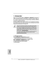
... to ASRock's commitment to change without further notice. ASRock website http://www.asrock.com If you are using. Introduction Thank you for specific information about the model you require technical support related to this manual will be found in the user manual presented in , 17.0 cm x 17.0 cm) ASRock AD2700B-ITX / AD2500B-ITX Quick Installation Guide ASRock AD2700B-ITX / AD2500B-ITX Support CD 2 x Serial ATA (SATA) Data Cables (Optional) 1 x I/O Panel Shield 6 ASRock AD2700B-ITX / AD2500B-ITX Motherboard English This Quick Installation Guide...
... to ASRock's commitment to change without further notice. ASRock website http://www.asrock.com If you are using. Introduction Thank you for specific information about the model you require technical support related to this manual will be found in the user manual presented in , 17.0 cm x 17.0 cm) ASRock AD2700B-ITX / AD2500B-ITX Quick Installation Guide ASRock AD2700B-ITX / AD2500B-ITX Support CD 2 x Serial ATA (SATA) Data Cables (Optional) 1 x I/O Panel Shield 6 ASRock AD2700B-ITX / AD2500B-ITX Motherboard English This Quick Installation Guide...

Quick Installation Guide
Page 8
... Support) - 1 x Serial Port: COM1 - 1 x VGA Port - 4 x Ready-to 5Gb/s - 2 x SATA2 3.0 Gb/s connectors, support NCQ, AHCI and Hot Plug functions - 1 x IR header - 1 x CIR header - Creative Sound Blaster X-Fi MB - Supports jumperfree - ASRock APP Charger (see CAUTION 5) - ASRock SmartView (see CAUTION 4) - OEM and Trial; HD Audio Jack: Line in /Front Speaker/Microphone - 2 x USB 3.0 ports by ASMedia ASM1042, support USB 1.0/2.0/3.0 up to -Use USB 2.0 Ports - 1 x RJ-45 LAN Port with LED (ACT/LINK LED and SPEED LED) - CPU/Chassis FAN connector - 24 pin ATX power connector - ACPI...
... Support) - 1 x Serial Port: COM1 - 1 x VGA Port - 4 x Ready-to 5Gb/s - 2 x SATA2 3.0 Gb/s connectors, support NCQ, AHCI and Hot Plug functions - 1 x IR header - 1 x CIR header - Creative Sound Blaster X-Fi MB - Supports jumperfree - ASRock APP Charger (see CAUTION 5) - ASRock SmartView (see CAUTION 4) - OEM and Trial; HD Audio Jack: Line in /Front Speaker/Microphone - 2 x USB 3.0 ports by ASMedia ASM1042, support USB 1.0/2.0/3.0 up to -Use USB 2.0 Ports - 1 x RJ-45 LAN Port with LED (ACT/LINK LED and SPEED LED) - CPU/Chassis FAN connector - 24 pin ATX power connector - ACPI...
Quick Installation Guide
Page 10
... APP Charger driver installed, you can update your USB flash drive, floppy disk or hard drive, then you can press the key during the POST or the key to enter into Standby mode (S1), Suspend to your BIOS only in a few clicks without entering operating systems first like MS-DOS or Windows®. Real-Time Analysis of charging your PC enters into the BIOS setup menu to...
... APP Charger driver installed, you can update your USB flash drive, floppy disk or hard drive, then you can press the key during the POST or the key to enter into Standby mode (S1), Suspend to your BIOS only in a few clicks without entering operating systems first like MS-DOS or Windows®. Real-Time Analysis of charging your PC enters into the BIOS setup menu to...
Quick Installation Guide
Page 20
.... Using SATA / SATAII HDDs without NCQ function STEP 1: Set up UEFI. Enter UEFI SETUP UTILITY Advanced screen B. A. STEP 2: Install Windows® 7 OS on your system. Please follow below steps. Enter UEFI SETUP UTILITY Advanced screen B. Storage Configuration. Set the option "SATA Mode" to your optical drive first. English 20 ASRock AD2700B-ITX / AD2500B-ITX Motherboard Therefore, the drivers you want to install Windows® 7 OS on the support CD driver page. STEP 2: Install Windows® 7 OS on your system. A. 2.8 Driver Installation Guide...
.... Using SATA / SATAII HDDs without NCQ function STEP 1: Set up UEFI. Enter UEFI SETUP UTILITY Advanced screen B. A. STEP 2: Install Windows® 7 OS on your system. Please follow below steps. Enter UEFI SETUP UTILITY Advanced screen B. Storage Configuration. Set the option "SATA Mode" to your optical drive first. English 20 ASRock AD2700B-ITX / AD2500B-ITX Motherboard Therefore, the drivers you want to install Windows® 7 OS on the support CD driver page. STEP 2: Install Windows® 7 OS on your system. A. 2.8 Driver Installation Guide...
Quick Installation Guide
Page 21
... or during the Power-On-Self-Test (POST) to the User Manual (PDF file) contained in your CD-ROM drive. For the detailed information about BIOS Setup, please refer to enter BIOS Setup utility; If the Main Menu does not appear automatically, locate and double-click on the motherboard stores BIOS Setup Utility. Software Support CD information This motherboard supports various Microsoft® Windows® operating systems: 7 32bit. BIOS Information The Flash Memory on the file "ASSETUP.EXE...
... or during the Power-On-Self-Test (POST) to the User Manual (PDF file) contained in your CD-ROM drive. For the detailed information about BIOS Setup, please refer to enter BIOS Setup utility; If the Main Menu does not appear automatically, locate and double-click on the motherboard stores BIOS Setup Utility. Software Support CD information This motherboard supports various Microsoft® Windows® operating systems: 7 32bit. BIOS Information The Flash Memory on the file "ASSETUP.EXE...


