
User Manual
Page 1
All rights reserved. 1 AD2700B-ITX / AD2500B-ITX User Manual Version 1.0 Published October 2011 Copyright©2011 ASRock INC.
All rights reserved. 1 AD2700B-ITX / AD2500B-ITX User Manual Version 1.0 Published October 2011 Copyright©2011 ASRock INC.

User Manual
Page 2
...the purchaser for identification or explanation and to the owners' benefit, without written consent of ASRock Inc. ASRock assumes no event shall ASRock, its directors, officers, employees, or agents be registered trademarks or copyrights of their respective ... not be reproduced, transcribed, transmitted, or translated in any language, in Perchlorate Best Management Practices (BMP) regulations passed by ASRock. Disclaimer: Specifications and information contained in this manual. In no responsibility for a particular purpose. This device complies ...
...the purchaser for identification or explanation and to the owners' benefit, without written consent of ASRock Inc. ASRock assumes no event shall ASRock, its directors, officers, employees, or agents be registered trademarks or copyrights of their respective ... not be reproduced, transcribed, transmitted, or translated in any language, in Perchlorate Best Management Practices (BMP) regulations passed by ASRock. Disclaimer: Specifications and information contained in this manual. In no responsibility for a particular purpose. This device complies ...
User Manual
Page 3
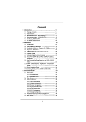
Contents 1 Introduction 5 1.1 Package Contents 5 1.2 Specifications 6 1.3 Motherboard Layout (AD2700B-ITX 11 1.4 Motherboard Layout (AD2500B-ITX 12 1.5 I/O Panel (AD2700B-ITX 13 1.6 I/O Panel (AD2500B-ITX 14 2 Installation 15 2.1 Screw Holes 15 2.2 Pre-installation Precautions 15 2.3 Installation of Memory Modules (SO-DIMM 16 2.4 Expansion Slot (PCI Slot 17 2.5 ASRock Smart Remote Installation Guide 18 2.6 Jumpers Setup 19 2.7 Onboard Headers and...
Contents 1 Introduction 5 1.1 Package Contents 5 1.2 Specifications 6 1.3 Motherboard Layout (AD2700B-ITX 11 1.4 Motherboard Layout (AD2500B-ITX 12 1.5 I/O Panel (AD2700B-ITX 13 1.6 I/O Panel (AD2500B-ITX 14 2 Installation 15 2.1 Screw Holes 15 2.2 Pre-installation Precautions 15 2.3 Installation of Memory Modules (SO-DIMM 16 2.4 Expansion Slot (PCI Slot 17 2.5 ASRock Smart Remote Installation Guide 18 2.6 Jumpers Setup 19 2.7 Onboard Headers and...

User Manual
Page 4
3.6 Security Screen 40 3.7 Exit Screen 41 4 Software Support 42 4.1 Install Operating System 42 4.2 Support CD Information 42 4.2.1 Running Support CD 42 4.2.2 Drivers Menu 42 4.2.3 Utilities Menu 42 4.2.4 Contact Information 42 4
3.6 Security Screen 40 3.7 Exit Screen 41 4 Software Support 42 4.1 Install Operating System 42 4.2 Support CD Information 42 4.2.1 Running Support CD 42 4.2.2 Drivers Menu 42 4.2.3 Utilities Menu 42 4.2.4 Contact Information 42 4
User Manual
Page 5
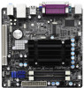
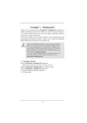
...stepby-step guide to change without further notice. www.asrock.com/support/index.asp 1.1 Package Contents ASRock AD2700B-ITX / AD2500B-ITX Motherboard (Mini-ITX Form Factor: 6.7-in x 6.7-in, 17.0 cm x 17.0 cm) ASRock AD2700B-ITX / AD2500B-ITX Quick Installation Guide ASRock AD2700B-ITX / AD2500B-ITX Support CD 2 x Serial ATA (SATA) Data...our website for specific information about the model you for purchasing ASRock AD2700B-ITX / AD2500B-ITX motherboard, a reliable motherboard produced under ASRock's consistently stringent quality control. You may find the latest VGA cards and...
...stepby-step guide to change without further notice. www.asrock.com/support/index.asp 1.1 Package Contents ASRock AD2700B-ITX / AD2500B-ITX Motherboard (Mini-ITX Form Factor: 6.7-in x 6.7-in, 17.0 cm x 17.0 cm) ASRock AD2700B-ITX / AD2500B-ITX Quick Installation Guide ASRock AD2700B-ITX / AD2500B-ITX Support CD 2 x Serial ATA (SATA) Data...our website for specific information about the model you for purchasing ASRock AD2700B-ITX / AD2500B-ITX motherboard, a reliable motherboard produced under ASRock's consistently stringent quality control. You may find the latest VGA cards and...

User Manual
Page 6
... RTL8111E - Supports Wake-On-LAN - Supports Energy Efficient Ethernet 802.3az - Solid Capacitor for CPU power (AD2500B-ITX) CPU - PCIE x1 Gigabit LAN 10/100/1000 Mb/s - Supports PXE Rear Panel I/O I/O Panel (AD2700B-ITX) - 1 x PS/2 Mouse Port - 1 x PS/2 Keyboard Port - 1 x Parallel Port (ECP/EPP Support) - 1 x Serial Port: COM1 - 1 x VGA Port - 2 x Ready...
... RTL8111E - Supports Wake-On-LAN - Supports Energy Efficient Ethernet 802.3az - Solid Capacitor for CPU power (AD2500B-ITX) CPU - PCIE x1 Gigabit LAN 10/100/1000 Mb/s - Supports PXE Rear Panel I/O I/O Panel (AD2700B-ITX) - 1 x PS/2 Mouse Port - 1 x PS/2 Keyboard Port - 1 x Parallel Port (ECP/EPP Support) - 1 x Serial Port: COM1 - 1 x VGA Port - 2 x Ready...

User Manual
Page 7
..., Utilities, AntiVirus Software (Trial Version), CyberLink MediaEspresso 6.5 Trial, ASRock Software Suite (CyberLink DVD Suite - HD Audio Jack: Line in /Front Speaker/Microphone I /O (AD2500B-ITX) USB 3.0 (AD2700B-ITX) Connector BIOS Feature Support CD Unique Feature - 1 x RJ-...45 LAN Port with GUI support - ASRock SmartView (see CAUTION 5) - Rear Panel I /O Panel - 1 x PS/2 Mouse Port - 1 x PS/2...
..., Utilities, AntiVirus Software (Trial Version), CyberLink MediaEspresso 6.5 Trial, ASRock Software Suite (CyberLink DVD Suite - HD Audio Jack: Line in /Front Speaker/Microphone I /O (AD2500B-ITX) USB 3.0 (AD2700B-ITX) Connector BIOS Feature Support CD Unique Feature - 1 x RJ-...45 LAN Port with GUI support - ASRock SmartView (see CAUTION 5) - Rear Panel I /O Panel - 1 x PS/2 Mouse Port - 1 x PS/2...

User Manual
Page 8
... not responsible for possible damage caused by overclocking. 8 Microsoft® Windows® 7 32-bit compliant Certifications - ASRock U-COP (see CAUTION 10) * For detailed product information, please visit our website: http://www.asrock.com WARNING Please realize that there is a certain risk involved with overclocking, including adjusting the setting in the...
... not responsible for possible damage caused by overclocking. 8 Microsoft® Windows® 7 32-bit compliant Certifications - ASRock U-COP (see CAUTION 10) * For detailed product information, please visit our website: http://www.asrock.com WARNING Please realize that there is a certain risk involved with overclocking, including adjusting the setting in the...

User Manual
Page 9
...Game: After setting online game's priority higher, it makes your iPhone charge much quickly from your computer and up to access ASRock Instant Flash. ASRock XFast USB can watch Youtube HD videos and download simultaneously. Traffic Shaping: You can boost USB storage device performance....newsfeed into the BIOS setup menu to 40% faster than 4GB for the reservation for a more personal Internet experience. ASRock website: http://www.asrock.com/Feature/AppCharger/index.asp 5. LAN Application Prioritization: You can lower the latency in touch with friends on the properties...
...Game: After setting online game's priority higher, it makes your iPhone charge much quickly from your computer and up to access ASRock Instant Flash. ASRock XFast USB can watch Youtube HD videos and download simultaneously. Traffic Shaping: You can boost USB storage device performance....newsfeed into the BIOS setup menu to 40% faster than 4GB for the reservation for a more personal Internet experience. ASRock website: http://www.asrock.com/Feature/AppCharger/index.asp 5. LAN Application Prioritization: You can lower the latency in touch with friends on the properties...

User Manual
Page 10
For EuP ready power supply selection, we recommend you install the PC system. 10. While CPU overheat is not recommended to define the power consumption for the completed system. According to EuP, the total AC power of the system or damage the CPU. 9. Frequencies other than 50% under 1.00W in off mode condition. According to check with the power supply manufacturer for Energy Using Product, was a provision regulated by the European Union to perform over-clocking. To improve heat dissipation, remember to spray thermal grease between the CPU and the heatsink when you to ...
For EuP ready power supply selection, we recommend you install the PC system. 10. While CPU overheat is not recommended to define the power consumption for the completed system. According to EuP, the total AC power of the system or damage the CPU. 9. Frequencies other than 50% under 1.00W in off mode condition. According to check with the power supply manufacturer for Energy Using Product, was a provision regulated by the European Union to perform over-clocking. To improve heat dissipation, remember to spray thermal grease between the CPU and the heatsink when you to ...

User Manual
Page 11
1.3 Motherboard Layout (AD2700B-ITX) PS2 Mouse PS2 Keyboard 1 2 3 17.0cm (6.7 in) CPU_FAN1 ErP/EuP Ready CHA_FAN1 4 Super IO 17.0cm (6.7 in) DDR3_A2 (64 bit, 204-FpiSnBm8o0d0ule) DDR3_A1 (64 bit, ...: Line Out Bottom: Mic In USB 3.0 T: USB2 B: USB3 RoHS USB 2.0 T: USB0 B: USB1 Top: RJ-45 AUDIO CODEC LAN PHY CMOS Battery 16Mb BIOS 1 HD_AUDIO1 AD2700B-ITX PCI1 DX10.1 Design in Taipei SATAII_1 SATAII_2 1 1 1 CIR1 SPEAKER1 1 USB6_7 IR1 1 USB4_5 PLED PWRBTN 1 HDLED RESET PANEL 1 CLRCMOS1 1 5 6 7 8 9 10 17 16 151413 12 11 1 CPU...
1.3 Motherboard Layout (AD2700B-ITX) PS2 Mouse PS2 Keyboard 1 2 3 17.0cm (6.7 in) CPU_FAN1 ErP/EuP Ready CHA_FAN1 4 Super IO 17.0cm (6.7 in) DDR3_A2 (64 bit, 204-FpiSnBm8o0d0ule) DDR3_A1 (64 bit, ...: Line Out Bottom: Mic In USB 3.0 T: USB2 B: USB3 RoHS USB 2.0 T: USB0 B: USB1 Top: RJ-45 AUDIO CODEC LAN PHY CMOS Battery 16Mb BIOS 1 HD_AUDIO1 AD2700B-ITX PCI1 DX10.1 Design in Taipei SATAII_1 SATAII_2 1 1 1 CIR1 SPEAKER1 1 USB6_7 IR1 1 USB4_5 PLED PWRBTN 1 HDLED RESET PANEL 1 CLRCMOS1 1 5 6 7 8 9 10 17 16 151413 12 11 1 CPU...

User Manual
Page 12
1.4 Motherboard Layout (AD2500B-ITX) PS2 Mouse PS2 Keyboard 1 2 3 17.0cm (6.7 in) CPU_FAN1 ErP/EuP Ready CHA_FAN1 4 Super IO 17.0cm (6.7 in) DDR3_A2 (64 bit, 204-FpiSnBm8o0d0ule) DDR3_A1 (64 bit, ... Center: Line Out Bottom: Mic In USB 2.0 T: USB2 B: USB3 RoHS USB 2.0 T: USB0 B: USB1 Top: RJ-45 AUDIO CODEC LAN PHY CMOS Battery 16Mb BIOS 1 HD_AUDIO1 AD2500B-ITX PCI1 DX10.1 Design in Taipei SATAII_1 SATAII_2 1 1 1 CIR1 SPEAKER1 1 USB6_7 IR1 1 USB4_5 PLED PWRBTN 1 HDLED RESET PANEL 1 CLRCMOS1 1 5 6 7 8 9 10 17 16 151413 12 11 1 CPU...
1.4 Motherboard Layout (AD2500B-ITX) PS2 Mouse PS2 Keyboard 1 2 3 17.0cm (6.7 in) CPU_FAN1 ErP/EuP Ready CHA_FAN1 4 Super IO 17.0cm (6.7 in) DDR3_A2 (64 bit, 204-FpiSnBm8o0d0ule) DDR3_A1 (64 bit, ... Center: Line Out Bottom: Mic In USB 2.0 T: USB2 B: USB3 RoHS USB 2.0 T: USB0 B: USB1 Top: RJ-45 AUDIO CODEC LAN PHY CMOS Battery 16Mb BIOS 1 HD_AUDIO1 AD2500B-ITX PCI1 DX10.1 Design in Taipei SATAII_1 SATAII_2 1 1 1 CIR1 SPEAKER1 1 USB6_7 IR1 1 USB4_5 PLED PWRBTN 1 HDLED RESET PANEL 1 CLRCMOS1 1 5 6 7 8 9 10 17 16 151413 12 11 1 CPU...

User Manual
Page 13
... the left side on your change. 13 In "Advanced Options" screen, select "Independent Headphone", and click "OK" to the front panel audio header. 1.5 I/O Panel (AD2700B-ITX) 1 2 11 10 9 1 PS/2 Mouse Port (Green) 2 Parallel Port * 3 LAN RJ-45 Port 4 Line In (Light Blue) 5 Front Speaker (Lime) 6 Microphone (Pink) 3 4 5 6 8 7 7 USB 2.0 Ports (USB01) 8 USB...
... the left side on your change. 13 In "Advanced Options" screen, select "Independent Headphone", and click "OK" to the front panel audio header. 1.5 I/O Panel (AD2700B-ITX) 1 2 11 10 9 1 PS/2 Mouse Port (Green) 2 Parallel Port * 3 LAN RJ-45 Port 4 Line In (Light Blue) 5 Front Speaker (Lime) 6 Microphone (Pink) 3 4 5 6 8 7 7 USB 2.0 Ports (USB01) 8 USB...

User Manual
Page 14
... To enable Multi-Streaming function, you need to connect a front panel audio cable to save your computer, you install. After restarting your change. 14 1.6 I/O Panel (AD2500B-ITX) 1 PS/2 Mouse Port (Green) 2 Parallel Port * 3 LAN RJ-45 Port 4 Line In (Light Blue) 5 Front Speaker (Lime) 6 Microphone (Pink) 7 USB 2.0 Ports (USB01) 8 USB 2.0 Ports (USB23...
... To enable Multi-Streaming function, you need to connect a front panel audio cable to save your computer, you install. After restarting your change. 14 1.6 I/O Panel (AD2500B-ITX) 1 PS/2 Mouse Port (Green) 2 Parallel Port * 3 LAN RJ-45 Port 4 Line In (Light Blue) 5 Front Speaker (Lime) 6 Microphone (Pink) 7 USB 2.0 Ports (USB01) 8 USB 2.0 Ports (USB23...

User Manual
Page 15
... detached from the wall socket before you install or remove any component, ensure that the power is switched off or the power cord is a Mini-ITX form factor (6.7" x 6.7", 17.0 x 17.0 cm) motherboard. Failure to do so may cause physical injuries to do so may damage the motherboard. 2.2 Pre-installation Precautions Take...
... detached from the wall socket before you install or remove any component, ensure that the power is switched off or the power cord is a Mini-ITX form factor (6.7" x 6.7", 17.0 x 17.0 cm) motherboard. Failure to do so may cause physical injuries to do so may damage the motherboard. 2.2 Pre-installation Precautions Take...

User Manual
Page 16
2.3 Installation of Memory Modules (SO-DIMM) AD2700B-ITX / AD2500B-ITX motherboard provides two 240-pin DDR3 (Double Data Rate 3) SO-DIMM slots. 1. Step 2. notch break notch break The SO-DIMM only fits in place ...
2.3 Installation of Memory Modules (SO-DIMM) AD2700B-ITX / AD2500B-ITX motherboard provides two 240-pin DDR3 (Double Data Rate 3) SO-DIMM slots. 1. Step 2. notch break notch break The SO-DIMM only fits in place ...

User Manual
Page 17
2.4 Expansion Slot (PCI Slot) There is completely seated on this motherboard. Please read the documentation of the expansion card and make sure that the power supply is switched off or the power cord is unplugged. Step 3. Step 6. Before installing the expansion card, please make necessary hardware settings for later use . Keep the screws for the card before you intend to use . Align the card connector with screws. Replace the system cover. 17 Remove the bracket facing the slot that has the 32-bit PCI interface. Step 5. Step 2. Step 4. Installing an expansion card Step ...
2.4 Expansion Slot (PCI Slot) There is completely seated on this motherboard. Please read the documentation of the expansion card and make sure that the power supply is switched off or the power cord is unplugged. Step 3. Step 6. Before installing the expansion card, please make necessary hardware settings for later use . Keep the screws for the card before you intend to use . Align the card connector with screws. Replace the system cover. 17 Remove the bracket facing the slot that has the 32-bit PCI interface. Step 5. Step 2. Step 4. Installing an expansion card Step ...

User Manual
Page 18
...on the rear panel. GND IRTX IRRX ATX+5VSB Install Multi-Angle CIR Receiver to below , pin 1-5) and the CIR header. Only one of ASRock motherboards. USB 2.0 header (9-pin, blue) CIR header (4-pin, white) Step2. If Multi-Angle CIR Receiver cannot successfully receive the infrared signals from...port will remain USB function. 2. Please refer to the USB_PWR USB 2.0 header (as below procedures for the motherboard support list: http://www.asrock.com 18 Please make sure the wire assignments and the PP+ GND DUMMY pin assignments are matched correctly. 1 23 45 Step3. The ...
...on the rear panel. GND IRTX IRRX ATX+5VSB Install Multi-Angle CIR Receiver to below , pin 1-5) and the CIR header. Only one of ASRock motherboards. USB 2.0 header (9-pin, blue) CIR header (4-pin, white) Step2. If Multi-Angle CIR Receiver cannot successfully receive the infrared signals from...port will remain USB function. 2. Please refer to the USB_PWR USB 2.0 header (as below procedures for the motherboard support list: http://www.asrock.com 18 Please make sure the wire assignments and the PP+ GND DUMMY pin assignments are matched correctly. 1 23 45 Step3. The ...

User Manual
Page 19
The illustration shows a 3-pin jumper whose pin1 and pin2 are setup. After waiting for 5 seconds. 19 Jumper Clear CMOS (CLRCMOS1, 2-pin jumper) (see p.11 or 12 No. 11) Setting 2-pin jumper Description Note: CLRCMOS1 allows you to clear the data in CMOS includes system setup information such as system password, date, time, and system setup parameters. To clear and reset the system parameters to short 2 pins on pins, the jumper is "Short". If no jumper cap is placed on pins, the jumper is placed on these 2 pins. 2.6 Jumpers Setup The illustration shows how jumpers are "...
The illustration shows a 3-pin jumper whose pin1 and pin2 are setup. After waiting for 5 seconds. 19 Jumper Clear CMOS (CLRCMOS1, 2-pin jumper) (see p.11 or 12 No. 11) Setting 2-pin jumper Description Note: CLRCMOS1 allows you to clear the data in CMOS includes system setup information such as system password, date, time, and system setup parameters. To clear and reset the system parameters to short 2 pins on pins, the jumper is "Short". If no jumper cap is placed on pins, the jumper is placed on these 2 pins. 2.6 Jumpers Setup The illustration shows how jumpers are "...

User Manual
Page 20
The current SATA2 interface allows up to the SATA / SATA2 hard disk or the SATA2 connector on this motherboard. Consumer Infrared Module Header (4-pin CIR1) (see p.11 or 12, No. 6) SATAII_1 SATAII_2 These two Serial ATA2 (SATA2) connectors support SATA data cables for internal storage devices. Placing jumper caps over these headers and connectors. Each USB 2.0 header can be used to connect the remote controller receiver. USB 2.0 Headers (9-pin USB4_5) (see p.11 or 12 No. 13) (9-pin USB6_7) (see p.11 or 12 No. 8) IRTX +5VSB DUMMY 1 GND IRRX This header supports an ...
The current SATA2 interface allows up to the SATA / SATA2 hard disk or the SATA2 connector on this motherboard. Consumer Infrared Module Header (4-pin CIR1) (see p.11 or 12, No. 6) SATAII_1 SATAII_2 These two Serial ATA2 (SATA2) connectors support SATA data cables for internal storage devices. Placing jumper caps over these headers and connectors. Each USB 2.0 header can be used to connect the remote controller receiver. USB 2.0 Headers (9-pin USB4_5) (see p.11 or 12 No. 13) (9-pin USB6_7) (see p.11 or 12 No. 8) IRTX +5VSB DUMMY 1 GND IRRX This header supports an ...