
User Manual
Page 4
... Software and Utilities Operation 27 3.1 Installing Drivers 27 3.2 A-Tuning 28 3.3 ASRock Live Update & APP Shop 31 4. Installation 10 2.1 CPU Installation 11 2.2 Installation of CPU Fan and Heatsink 12 2.3 Installation of Memory Modules (DIMM) 13 2.4 Expansion Slots (PCI and PCI Express Slots) 15 2.5 Jumpers Setup 16 2.6 Onboard Headers and Connectors 17 2.7 AMD Dual Graphics Operation Guide 22 2.8 M.2_SSD (NGFF) Module Installation Guide 24 3. Contents 1. Introduction 1 1.1 Package Contents 1 1.2 Specifications 2 1.3 Motherboard Layout 6 1.4 I/O Panel...
... Software and Utilities Operation 27 3.1 Installing Drivers 27 3.2 A-Tuning 28 3.3 ASRock Live Update & APP Shop 31 4. Installation 10 2.1 CPU Installation 11 2.2 Installation of CPU Fan and Heatsink 12 2.3 Installation of Memory Modules (DIMM) 13 2.4 Expansion Slots (PCI and PCI Express Slots) 15 2.5 Jumpers Setup 16 2.6 Onboard Headers and Connectors 17 2.7 AMD Dual Graphics Operation Guide 22 2.8 M.2_SSD (NGFF) Module Installation Guide 24 3. Contents 1. Introduction 1 1.1 Package Contents 1 1.2 Specifications 2 1.3 Motherboard Layout 6 1.4 I/O Panel...
User Manual
Page 6
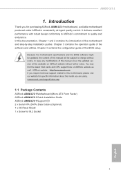
..., the updated version will be available on ASRock website as well. A88M-G/3.1 1. In this motherboard, please visit our website for specific information about the model you for M.2 Socket 1 English You may find the latest VGA cards and CPU support lists on ASRock website without notice. Chapter 4 contains the configuration guide of the software and utilities. www.asrock.com/support/index.asp 1.1 Package Contents ASRock A88M-G/3.1 Motherboard (Micro ATX Form Factor) ASRock A88M-G/3.1 Quick Installation Guide ASRock A88M-G/3.1 Support CD 2 x Serial ATA (SATA) Data Cables...
..., the updated version will be available on ASRock website as well. A88M-G/3.1 1. In this motherboard, please visit our website for specific information about the model you for M.2 Socket 1 English You may find the latest VGA cards and CPU support lists on ASRock website without notice. Chapter 4 contains the configuration guide of the software and utilities. www.asrock.com/support/index.asp 1.1 Package Contents ASRock A88M-G/3.1 Motherboard (Micro ATX Form Factor) ASRock A88M-G/3.1 Quick Installation Guide ASRock A88M-G/3.1 Support CD 2 x Serial ATA (SATA) Data Cables...
User Manual
Page 9
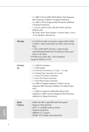
... SPEED LED) • HD Audio Jacks: Rear Speaker / Central / Bass / Line in / Front Speaker / Microphone • 8 x SATA3 6.0 Gb/s Connectors, support RAID (RAID 0, RAID 1, RAID 5 and RAID 10), NCQ, AHCI and Hot Plug • 1 x M.2_SSD (NGFF) Socket 3, supports type 2230/2242/2260/2280 M.2 PCI Express module up to Gen2 x4 (20 Gb/s) * If PCIE3 is occupied, M2_1 will be disabled. * Supports ASRock U.2 Kit • 1 x COM Port Headerr • 1 x TPM Header • 2 x CPU Fan Connectors (1 x 4-pin, 1 x 3-pin) • 2 x Chassis Fan Connectors (2 x 4-pin) • 1 x 24 pin ATX Power Connector...
... SPEED LED) • HD Audio Jacks: Rear Speaker / Central / Bass / Line in / Front Speaker / Microphone • 8 x SATA3 6.0 Gb/s Connectors, support RAID (RAID 0, RAID 1, RAID 5 and RAID 10), NCQ, AHCI and Hot Plug • 1 x M.2_SSD (NGFF) Socket 3, supports type 2230/2242/2260/2280 M.2 PCI Express module up to Gen2 x4 (20 Gb/s) * If PCIE3 is occupied, M2_1 will be disabled. * Supports ASRock U.2 Kit • 1 x COM Port Headerr • 1 x TPM Header • 2 x CPU Fan Connectors (1 x 4-pin, 1 x 3-pin) • 2 x Chassis Fan Connectors (2 x 4-pin) • 1 x 24 pin ATX Power Connector...
User Manual
Page 10
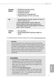
... For Windows® 64-bit OS with overclocking, including adjusting the setting in the BIOS, applying Untied Overclocking Technology, or using third-party overclocking tools. A88M-G/3.1 Hardware Monitor • CPU/Chassis temperature sensing • CPU/Chassis Tachometer • CPU/Chassis Quiet Fan • CPU/Chassis Fan multi-speed control • Voltage monitoring: +12V, +5V, +3.3V, Vcore OS • Microsoft® Windows® 10 32-bit / 10 64-bit / 8.1 32-bit / 8.1 64-bit / 7 32-bit / 7 64-bit * For the updated Windows® 10 driver, please visit ASRock's website...
... For Windows® 64-bit OS with overclocking, including adjusting the setting in the BIOS, applying Untied Overclocking Technology, or using third-party overclocking tools. A88M-G/3.1 Hardware Monitor • CPU/Chassis temperature sensing • CPU/Chassis Tachometer • CPU/Chassis Quiet Fan • CPU/Chassis Fan multi-speed control • Voltage monitoring: +12V, +5V, +3.3V, Vcore OS • Microsoft® Windows® 10 32-bit / 10 64-bit / 8.1 32-bit / 8.1 64-bit / 7 32-bit / 7 64-bit * For the updated Windows® 10 driver, please visit ASRock's website...

User Manual
Page 12
...240-pin DDR3 DIMM Slots (DDR3_A2, DDR3_B2) 6 ATX Power Connector (ATXPWR1) 7 USB 3.0 Header (USB3_3_4) 8 SATA3 Connector (SATA3_7) 9 SATA3 Connector (SATA3_8) 10 SATA3 Connector (SATA3_5) 11 SATA3 Connector (SATA3_6) 12 Clear CMOS Jumper (CLRCMOS1) 13 SATA3 Connector (SATA3_4) 14 SATA3 Connector (SATA3_3) 15 SATA3 Connector (SATA3_2) 16 SATA3 Connector (SATA3_1) 17 Power LED Header (PLED1) 18 System Panel Header (PANEL1) 19 Chassis Speaker Header (SPEAKER1) 20 Chassis Fan Connector (CHA_FAN2) 21 USB 2.0 Header (USB_3_4) 22 USB 2.0 Header (USB_5_6) 23 TPM Header (TPMS1) 24 COM Port Header (COM1...
...240-pin DDR3 DIMM Slots (DDR3_A2, DDR3_B2) 6 ATX Power Connector (ATXPWR1) 7 USB 3.0 Header (USB3_3_4) 8 SATA3 Connector (SATA3_7) 9 SATA3 Connector (SATA3_8) 10 SATA3 Connector (SATA3_5) 11 SATA3 Connector (SATA3_6) 12 Clear CMOS Jumper (CLRCMOS1) 13 SATA3 Connector (SATA3_4) 14 SATA3 Connector (SATA3_3) 15 SATA3 Connector (SATA3_2) 16 SATA3 Connector (SATA3_1) 17 Power LED Header (PLED1) 18 System Panel Header (PANEL1) 19 Chassis Speaker Header (SPEAKER1) 20 Chassis Fan Connector (CHA_FAN2) 21 USB 2.0 Header (USB_3_4) 22 USB 2.0 Header (USB_5_6) 23 TPM Header (TPMS1) 24 COM Port Header (COM1...

User Manual
Page 20
... switched off or the power cord is used to the motherboard's chassis fan connector (CHA_FAN1 or CHA_FAN2) when using multiple graphics cards. PCIE3 (PCIe 2.0 x16 slot) is used for the card before you start the installation. English 15 PCIE1 (PCIe 3.0 x16 slot) is used for PCI Express cards with x1 lane width cards. PCIe Slot Configurations Single Graphics Card PCIE1 x16 PCIE3 N/A Two Graphics Cards in CrossFireXTM Mode x16 x4 For a better thermal environment, please connect a chassis fan to install expansion cards that have the 32-bit PCI...
... switched off or the power cord is used to the motherboard's chassis fan connector (CHA_FAN1 or CHA_FAN2) when using multiple graphics cards. PCIE3 (PCIe 2.0 x16 slot) is used for the card before you start the installation. English 15 PCIE1 (PCIe 3.0 x16 slot) is used for PCI Express cards with x1 lane width cards. PCIe Slot Configurations Single Graphics Card PCIE1 x16 PCIE3 N/A Two Graphics Cards in CrossFireXTM Mode x16 x4 For a better thermal environment, please connect a chassis fan to install expansion cards that have the 32-bit PCI...
User Manual
Page 21
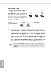
... is placed on pins, the jumper is removed. After waiting for 15 seconds, use a jumper cap to clear the record of previous chassis intrusion status. If you need to default setup, please turn off the computer and unplug the power cord from the power supply. To clear and reset the system parameters to clear the CMOS when you just finish updating the BIOS, you must boot up the system first...
... is placed on pins, the jumper is removed. After waiting for 15 seconds, use a jumper cap to clear the record of previous chassis intrusion status. If you need to default setup, please turn off the computer and unplug the power cord from the power supply. To clear and reset the system parameters to clear the CMOS when you just finish updating the BIOS, you must boot up the system first...

User Manual
Page 27
... an AMD Radeon HD 8000/7000 graphics processor and a motherboard based on [Auto]. Enjoy the benefit of "Dual Graphics" option on an AMD A78 (Bolton-D3) integrated chipset, all operating in your computer. Please keep the default UEFI setting of AMD Dual Graphics Step 1. Connect the monitor cable to enter AMD VISION Engine Control Center. 22 English Please remove the AMD driver if you have any future update, please refer to PCIE1 slot. Install the onboard VGA driver from onboard display only. AMD Dual Graphics brings...
... an AMD Radeon HD 8000/7000 graphics processor and a motherboard based on [Auto]. Enjoy the benefit of "Dual Graphics" option on an AMD A78 (Bolton-D3) integrated chipset, all operating in your computer. Please keep the default UEFI setting of AMD Dual Graphics Step 1. Connect the monitor cable to enter AMD VISION Engine Control Center. 22 English Please remove the AMD driver if you have any future update, please refer to PCIE1 slot. Install the onboard VGA driver from onboard display only. AMD Dual Graphics brings...
User Manual
Page 32
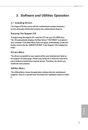
... the motherboard contains necessary drivers and useful utilities that the motherboard supports. If the Main Menu does not appear automatically, locate and double click on the file "ASRSETUP.EXE" in your CD-ROM drive. Running The Support CD To begin using the support CD, insert the CD into your computer. Click on the support CD driver page. A88M-G/3.1 3. Therefore, the drivers you install can work properly. The CD automatically displays the Main Menu if...
... the motherboard contains necessary drivers and useful utilities that the motherboard supports. If the Main Menu does not appear automatically, locate and double click on the file "ASRSETUP.EXE" in your CD-ROM drive. Running The Support CD To begin using the support CD, insert the CD into your computer. Click on the support CD driver page. A88M-G/3.1 3. Therefore, the drivers you install can work properly. The CD automatically displays the Main Menu if...
User Manual
Page 42
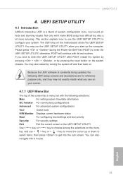
... following selections: Main For setting system time/date information OC Tweaker For overclocking configurations Advanced For advanced system configurations Tool Useful tools H/W Monitor Displays current hardware status Boot For configuring boot settings and boot priority Security For security settings Exit Exit the current screen or the UEFI Setup Utility Use < > key or < > key to get into the sub screen. Please press or during the Power-On-Self-Test (POST) to enter the UEFI Setup Utility after POST, restart the...
... following selections: Main For setting system time/date information OC Tweaker For overclocking configurations Advanced For advanced system configurations Tool Useful tools H/W Monitor Displays current hardware status Boot For configuring boot settings and boot priority Security For security settings Exit Exit the current screen or the UEFI Setup Utility Use < > key or < > key to get into the sub screen. Please press or during the Power-On-Self-Test (POST) to enter the UEFI Setup Utility after POST, restart the...
User Manual
Page 44
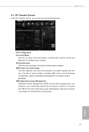
... Tweaker screen, you adopt supports this feature. Configuration options: [Enabled] and [Disabled]. AMD Application power Management Application Power Management (APM) ensures that average power consumption over a thermally significant time period remains at or below the TDP for better system stability. If [Enabled] is selected, the power consumption is [Enabled]. The default value is [Auto]. AMD Turbo Core Technology This item appears only when the processor you can set up overclocking features...
... Tweaker screen, you adopt supports this feature. Configuration options: [Enabled] and [Disabled]. AMD Application power Management Application Power Management (APM) ensures that average power consumption over a thermally significant time period remains at or below the TDP for better system stability. If [Enabled] is selected, the power consumption is [Enabled]. The default value is [Auto]. AMD Turbo Core Technology This item appears only when the processor you can set up overclocking features...

User Manual
Page 46
Power Down Enable Use this to select DRAM Voltage. Configuration options: [Disabled], [Auto]. Voltage Configuration DRAM Voltage Use this item to enable or disable DDR power down mode. The default value is [Auto]. 41 English SB Voltage Use this to select APU PCIE Voltage VDDP. APU PCIE Voltage VDDP Use this to select SB Voltage. The default value is [Auto]. DRAM Timing Control Use this item to view SPD data. Channel Interleaving It allows you to be spread out over banks on the same node...
Power Down Enable Use this to select DRAM Voltage. Configuration options: [Disabled], [Auto]. Voltage Configuration DRAM Voltage Use this item to enable or disable DDR power down mode. The default value is [Auto]. 41 English SB Voltage Use this to select APU PCIE Voltage VDDP. APU PCIE Voltage VDDP Use this to select SB Voltage. The default value is [Auto]. DRAM Timing Control Use this item to view SPD data. Channel Interleaving It allows you to be spread out over banks on the same node...

User Manual
Page 49
... Function Use this feature is [PCI Express]. Configuration options: [as Dual Link DVI] and [as Dual Link DVI], you select [as Dual Link DVI]. 44 English Share Memory This allows you to enable or disable the "Onboard HDMI HD Audio" feature. Onboard Graphics Select Enable/Disable/Auto for video card. The default value of multiple video controllers. If you can use Dual Link DVI monitor without audio function. It allows you to select the type of Primary VGA in case of...
... Function Use this feature is [PCI Express]. Configuration options: [as Dual Link DVI] and [as Dual Link DVI], you select [as Dual Link DVI]. 44 English Share Memory This allows you to enable or disable the "Onboard HDMI HD Audio" feature. Onboard Graphics Select Enable/Disable/Auto for video card. The default value of multiple video controllers. If you can use Dual Link DVI monitor without audio function. It allows you to select the type of Primary VGA in case of...
User Manual
Page 51
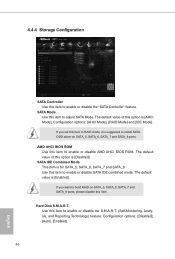
...or disable SATA IDE combined mode. Configuration options: [Disabled], [Auto], [Enabled]. 46 English The default value of this option is [AHCI Mode]. The default value is for SATA_5, SATA_6, SATA_7 and SATA_8. If you want to enable or disable AMD AHCI BIOS ROM. Use this item to RAID mode, it is [Disabled]. Configuration options: [AHCI Mode], [RAID Mode] and [IDE Mode]. SATA IDE Combined Mode This item is [Enabled]. Hard Disk S.M.A.R.T. AMD AHCI BIOS ROM Use this item to build RAID on SATA_5, SATA_6, SATA_7 and SATA_8 ports. If you set this item to install SATA ODD driver...
...or disable SATA IDE combined mode. Configuration options: [Disabled], [Auto], [Enabled]. 46 English The default value of this option is [AHCI Mode]. The default value is for SATA_5, SATA_6, SATA_7 and SATA_8. If you want to enable or disable AMD AHCI BIOS ROM. Use this item to RAID mode, it is [Disabled]. Configuration options: [AHCI Mode], [RAID Mode] and [IDE Mode]. SATA IDE Combined Mode This item is [Enabled]. Hard Disk S.M.A.R.T. AMD AHCI BIOS ROM Use this item to build RAID on SATA_5, SATA_6, SATA_7 and SATA_8 ports. If you set this item to install SATA ODD driver...

User Manual
Page 52
Parallel Port Enable or disable the Parallel port. English 47 Configuration options: [3F8h / IRQ4] and [3E8h / IRQ4]. Serial Port Address Use this item to enable or disable the onboard serial port. Serial Port Use this item to set this option to your connected device. 4.4.5 Super IO Configuration A88M-G/3.1 PS2 Y-Cable Enable the PS2 Y-Cable or set the address for the onboard serial port. Change Settings Select the address of the Parallel port. Device Mode Select the device mode according to Auto.
Parallel Port Enable or disable the Parallel port. English 47 Configuration options: [3F8h / IRQ4] and [3E8h / IRQ4]. Serial Port Address Use this item to enable or disable the onboard serial port. Serial Port Use this item to set this option to your connected device. 4.4.5 Super IO Configuration A88M-G/3.1 PS2 Y-Cable Enable the PS2 Y-Cable or set the address for the onboard serial port. Change Settings Select the address of the Parallel port. Device Mode Select the device mode according to Auto.

User Manual
Page 53
... mode. Check Ready Bit Enable to power on the system from the power-soft-off mode. 4.4.6 ACPI Configuration Suspend to RAM Use this item to select whether to boot up when the power recovers. If [Power On] is recommended for better system stability. Deep Sleep Configure deep sleep mode for better system compatibility and stability. PCI Devices Power On Use this item to enable or disable PCI devices to set the power state after S3 only when the hard disk...
... mode. Check Ready Bit Enable to power on the system from the power-soft-off mode. 4.4.6 ACPI Configuration Suspend to RAM Use this item to select whether to boot up when the power recovers. If [Power On] is recommended for better system stability. Deep Sleep Configure deep sleep mode for better system compatibility and stability. PCI Devices Power On Use this item to enable or disable PCI devices to set the power state after S3 only when the hard disk...

User Manual
Page 55
... USB Support Use this option to enable or disable legacy support for USB devices. Enables legacy support if USB devices are four confi guration options: [Enabled], [Auto], [Disabled] and [UEFI Setup Only]. Legacy USB 3.0 Support Use this option to select legacy support for USB 3.0 devices. Please refer to enter OS. [UEFI Setup Only] - USB devices are not allowed to use of USB 3.0 controller. 4.4.7 USB Configuration USB 2.0 Controller Use this item to enable or disable the use only under legacy OS and UEFI setup when [Disabled] is selected. The default value is [Enabled...
... USB Support Use this option to enable or disable legacy support for USB devices. Enables legacy support if USB devices are four confi guration options: [Enabled], [Auto], [Disabled] and [UEFI Setup Only]. Legacy USB 3.0 Support Use this option to select legacy support for USB 3.0 devices. Please refer to enter OS. [UEFI Setup Only] - USB devices are not allowed to use of USB 3.0 controller. 4.4.7 USB Configuration USB 2.0 Controller Use this item to enable or disable the use only under legacy OS and UEFI setup when [Disabled] is selected. The default value is [Enabled...
User Manual
Page 57
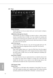
UEFI Update Utility Instant Flash Instant Flash is a handy tool in the UEFI that don't have an optical disk drive to install the drivers from our support CD, Easy Driver Installer is a UEFI flash utility embedded in Flash ROM. This convenient UEFI update tool allows you can let you easily check your USB storage device. UEFI Tech Service Contact ASRock Tech Service if you are required. After copying the drivers please change the SATA mode to RAID, then you to update system UEFI without permission...
UEFI Update Utility Instant Flash Instant Flash is a handy tool in the UEFI that don't have an optical disk drive to install the drivers from our support CD, Easy Driver Installer is a UEFI flash utility embedded in Flash ROM. This convenient UEFI update tool allows you can let you easily check your USB storage device. UEFI Tech Service Contact ASRock Tech Service if you are required. After copying the drivers please change the SATA mode to RAID, then you to update system UEFI without permission...

User Manual
Page 59
...]. Use this option to keep or clear the record of the CPU temperature, motherboard temperature, CPU fan speed, chassis fan speed, and the critical voltage. Chassis Fan 2 Setting This allows you to set the CPU fan 1 & 2 speed. Chassis Fan 2 Temp Source Select a fan temperature source for Chassis Fan 1. Case Open Feature This allows you to enable or disable case open has been detected. The default is value [Full On]. CPU Fan 1 & 2 Setting This allows you to set the chassis fan 2 speed. Confi guration options: [Full On], [Manual Mode] and [Automatic Mode]. The default is...
...]. Use this option to keep or clear the record of the CPU temperature, motherboard temperature, CPU fan speed, chassis fan speed, and the critical voltage. Chassis Fan 2 Setting This allows you to set the CPU fan 1 & 2 speed. Chassis Fan 2 Temp Source Select a fan temperature source for Chassis Fan 1. Case Open Feature This allows you to enable or disable case open has been detected. The default is value [Full On]. CPU Fan 1 & 2 Setting This allows you to set the chassis fan 2 speed. Confi guration options: [Full On], [Manual Mode] and [Automatic Mode]. The default is...
User Manual
Page 60
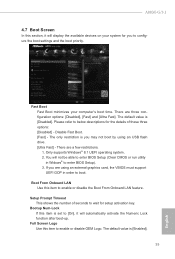
... to enable or disable the Boot From Onboard LAN feature. The default value is [Enabled]. 55 English You will not be able to enter BIOS Setup (Clear CMOS or run utility in order to enter BIOS Setup). 3. If you may not boot by using an external graphics card, the VBIOS must support UEFI GOP in Widows® to boot. The default value is [Disabled]. The only restriction is set to enable or disable OEM Logo. There are three configuration options: [Disabled...
... to enable or disable the Boot From Onboard LAN feature. The default value is [Enabled]. 55 English You will not be able to enter BIOS Setup (Clear CMOS or run utility in order to enter BIOS Setup). 3. If you may not boot by using an external graphics card, the VBIOS must support UEFI GOP in Widows® to boot. The default value is [Disabled]. The only restriction is set to enable or disable OEM Logo. There are three configuration options: [Disabled...


