
User Manual
Page 3
Installation 15 Pre-installation Precautions 15 2.1 CPU Installation 16 2.2 Installation of CPU Fan and Heatsink 16 2.3 Installation of Memory Modules (DIMM 17 2.4 Expansion Slots (PCI and PCI Express Slots 18 2.5 Dual Monitor and Surround Display Features 19 2.6 ATITM ...
Installation 15 Pre-installation Precautions 15 2.1 CPU Installation 16 2.2 Installation of CPU Fan and Heatsink 16 2.3 Installation of Memory Modules (DIMM 17 2.4 Expansion Slots (PCI and PCI Express Slots 18 2.5 Dual Monitor and Surround Display Features 19 2.6 ATITM ...

User Manual
Page 7
...FAN connector - 24 pin ATX power connector - 4 pin 12V power connector - Supports jumperfree - VCCM, NB Voltage Multi-adjustment - ASRock OC Tuner (see CAUTION 10) - Intelligent Energy Saver (see CAUTION 9) - ASRock OC DNA (see CAUTION 14) - Hybrid Booster: - AMI Legal BIOS - Supports "Plug and Play" - Explorer, AMD Fusion - Instant Boot - ASRock... - 3 x USB 2.0 headers (support 6 USB 2.0 ports) (see CAUTION 13) - ACPI 1.1 Compliance Wake Up Events - ASRock Instant Flash (see CAUTION 7) - 1 x ATA133 IDE connector (supports 2 x IDE devices) - 1 x Floppy connector - 1...
...FAN connector - 24 pin ATX power connector - 4 pin 12V power connector - Supports jumperfree - VCCM, NB Voltage Multi-adjustment - ASRock OC Tuner (see CAUTION 10) - Intelligent Energy Saver (see CAUTION 9) - ASRock OC DNA (see CAUTION 14) - Hybrid Booster: - AMI Legal BIOS - Supports "Plug and Play" - Explorer, AMD Fusion - Instant Boot - ASRock... - 3 x USB 2.0 headers (support 6 USB 2.0 ports) (see CAUTION 13) - ACPI 1.1 Compliance Wake Up Events - ASRock Instant Flash (see CAUTION 7) - 1 x ATA133 IDE connector (supports 2 x IDE devices) - 1 x Floppy connector - 1...

User Manual
Page 8
...4. Please check AMD website for proper installation. 3. ASRock AM2 Boost: ASRock Patented Technology to boost memory performance up to the memory support list on our website for system usage under Windows® XP and Windows® VistaTM. CPU/Chassis/Power Fan Tachometer - Microsoft® Windows® XP / ...on this motherboard, please refer to 12.5% (see CAUTION 16) * For detailed product information, please visit our website: http://www.asrock.com WARNING Please realize that there is a certain risk involved with 64-bit CPU, there is subject to the components and devices of...
...4. Please check AMD website for proper installation. 3. ASRock AM2 Boost: ASRock Patented Technology to boost memory performance up to the memory support list on our website for system usage under Windows® XP and Windows® VistaTM. CPU/Chassis/Power Fan Tachometer - Microsoft® Windows® XP / ...on this motherboard, please refer to 12.5% (see CAUTION 16) * For detailed product information, please visit our website: http://www.asrock.com WARNING Please realize that there is a certain risk involved with 64-bit CPU, there is subject to the components and devices of...

User Manual
Page 10
Before you resume the system, please check if the CPU fan on the AM2 CPU you enable this function in off mode condition. If you adopt. According to 12.5%, but the effect still depends on the ... an EuP ready power supply are required. According to your system is unstable after AM2 Boost function is enabled, it back again. This motherboard supports ASRock AM2 Boost overclocking technology. You may not be under 100 mA current consumption. Enabling this function for the completed system. However, we recommend you install...
Before you resume the system, please check if the CPU fan on the AM2 CPU you enable this function in off mode condition. If you adopt. According to 12.5%, but the effect still depends on the ... an EuP ready power supply are required. According to your system is unstable after AM2 Boost function is enabled, it back again. This motherboard supports ASRock AM2 Boost overclocking technology. You may not be under 100 mA current consumption. Enabling this function for the completed system. However, we recommend you install...

User Manual
Page 13
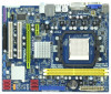
...LINE IN Center: FRONT Bottom: MIC IN LAN AUDIO CODEC Super I/O CD1 1 HD_AUDIO1 LPT1 1 1 COM1 HT3.0 Hybrid CrossFire PCIE1 AMD 785G Chipset A785GM-LE PCIE2 IDE1 PWR_FAN1 SATAII_4 SATAII_5 SATAII_6 (PORT 3) (PORT 4) (PORT 5) RoHS PCI1 IR1 1 FLOPPY1 PCI2 USB10_11 1 AMD SB710 Chipset SPEAKER1 1 PLED... 16 17 1 ATX 12V Power Connector (ATX12V1) 19 Primary SATAII Connector 2 PS2_USB_PW1 Jumper (SATAII_1 (PORT 0)) 3 CPU Heatsink Retention Module 20 Chassis Fan Connector (CHA_FAN1) 4 AM2 940-Pin CPU Socket 21 USB 2.0 Header (USB6_7, Blue) 5 2 x 240-pin DDR2 DIMM Slots 22 SPI Flash...
...LINE IN Center: FRONT Bottom: MIC IN LAN AUDIO CODEC Super I/O CD1 1 HD_AUDIO1 LPT1 1 1 COM1 HT3.0 Hybrid CrossFire PCIE1 AMD 785G Chipset A785GM-LE PCIE2 IDE1 PWR_FAN1 SATAII_4 SATAII_5 SATAII_6 (PORT 3) (PORT 4) (PORT 5) RoHS PCI1 IR1 1 FLOPPY1 PCI2 USB10_11 1 AMD SB710 Chipset SPEAKER1 1 PLED... 16 17 1 ATX 12V Power Connector (ATX12V1) 19 Primary SATAII Connector 2 PS2_USB_PW1 Jumper (SATAII_1 (PORT 0)) 3 CPU Heatsink Retention Module 20 Chassis Fan Connector (CHA_FAN1) 4 AM2 940-Pin CPU Socket 21 USB 2.0 Header (USB6_7, Blue) 5 2 x 240-pin DDR2 DIMM Slots 22 SPI Flash...

User Manual
Page 16
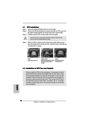
...is locked. DO NOT force the CPU into this motherboard, it fits in place, press it is necessary to install a larger heatsink and cooling fan to indicate that the CPU corner with the golden triangle matches the socket corner with each other. The lever clicks on the socket while you...a 90o angle. Step 3. You also need to spray thermal grease between the CPU and the heatsink to the CPU FAN connector (CPU_FAN1, see Page 13, No. 6). Step 2. Then connect the CPU fan to improve heat dissipation. Step 4. Lever 90° Up CPU Golden Triangle STEP 1: Lift Up The Socket Lever Socket...
...is locked. DO NOT force the CPU into this motherboard, it fits in place, press it is necessary to install a larger heatsink and cooling fan to indicate that the CPU corner with the golden triangle matches the socket corner with each other. The lever clicks on the socket while you...a 90o angle. Step 3. You also need to spray thermal grease between the CPU and the heatsink to the CPU FAN connector (CPU_FAN1, see Page 13, No. 6). Step 2. Then connect the CPU fan to improve heat dissipation. Step 4. Lever 90° Up CPU Golden Triangle STEP 1: Lift Up The Socket Lever Socket...

User Manual
Page 28
... +12V PWR_FAN_SPEED 4 3 2 1 GND +12V CPU_FAN_SPEED FAN_SPEED_CONTROL Please connect the chassis speaker to do so will cause power up failure. 28 Pin 1-3 Connected 3-Pin Fan Installation ATX Power Connector (24-pin ATXPWR1) (see p.13 No. 1) 20-Pin ATX Power Supply Installation 1 13 Please note that it is necessary to this...an ATX power supply to this connector. 1 13 Though this motherboard provides 24-pin ATX power connector, 12 24 it to the CPU fan connector on this connector and match the black wire to the ground pin. To use the 20-pin ATX power supply, please plug your...
... +12V PWR_FAN_SPEED 4 3 2 1 GND +12V CPU_FAN_SPEED FAN_SPEED_CONTROL Please connect the chassis speaker to do so will cause power up failure. 28 Pin 1-3 Connected 3-Pin Fan Installation ATX Power Connector (24-pin ATXPWR1) (see p.13 No. 1) 20-Pin ATX Power Supply Installation 1 13 Please note that it is necessary to this...an ATX power supply to this connector. 1 13 Though this motherboard provides 24-pin ATX power connector, 12 24 it to the CPU fan connector on this connector and match the black wire to the ground pin. To use the 20-pin ATX power supply, please plug your...

User Manual
Page 59
... SETUP UTILITY Main OC Tweaker Advanced H/W Monitor Boot Security Exit Hardware Health Event Monitoring CPU Temperature M / B Temperature CPU Fan Speed Chassis Fan Speed Power Fan Speed Vcore + 3.30V + 5.00V + 12.00V CPU Quiet Fan : 37 C / 98 F : 27 C / 80 F : 4722 RPM : N/A : N/A : 1.216V :...according to enable this function only when you to identify the temperature of the CPU temperature, motherboard temperature, CPU fan speed, chassis fan speed, and the critical voltage. Target Fan Speed Use this section, it allows you choose. Configuration options: [Level 1], [Level 2], [Level 3], ...
... SETUP UTILITY Main OC Tweaker Advanced H/W Monitor Boot Security Exit Hardware Health Event Monitoring CPU Temperature M / B Temperature CPU Fan Speed Chassis Fan Speed Power Fan Speed Vcore + 3.30V + 5.00V + 12.00V CPU Quiet Fan : 37 C / 98 F : 27 C / 80 F : 4722 RPM : N/A : N/A : 1.216V :...according to enable this function only when you to identify the temperature of the CPU temperature, motherboard temperature, CPU fan speed, chassis fan speed, and the critical voltage. Target Fan Speed Use this section, it allows you choose. Configuration options: [Level 1], [Level 2], [Level 3], ...

Quick Installation Guide
Page 2
... Orange) 34 Serial Port Connector (COM1) 17 Third SATAII Connector (SATAII_3 (PORT 2)) 18 Secondary SATAII Connector (SATAII_2 (PORT 1)) 2 ASRock A785GM-LE Motherboard Motherboard Layout 12 1 PS2_USB_PW1 34 19.8cm (7.8-in) PS2 Mouse PS2 Keyboard VGA1 ATX12V1 Phenom II DDR2 1066 Dual Channel 56 ...17 English 1 ATX 12V Power Connector (ATX12V1) 19 Primary SATAII Connector 2 PS2_USB_PW1 Jumper (SATAII_1 (PORT 0)) 3 CPU Heatsink Retention Module 20 Chassis Fan Connector (CHA_FAN1) 4 AM2 940-Pin CPU Socket 21 USB 2.0 Header (USB6_7, Blue) 5 2 x 240-pin DDR2 DIMM Slots 22 SPI ...
... Orange) 34 Serial Port Connector (COM1) 17 Third SATAII Connector (SATAII_3 (PORT 2)) 18 Secondary SATAII Connector (SATAII_2 (PORT 1)) 2 ASRock A785GM-LE Motherboard Motherboard Layout 12 1 PS2_USB_PW1 34 19.8cm (7.8-in) PS2 Mouse PS2 Keyboard VGA1 ATX12V1 Phenom II DDR2 1066 Dual Channel 56 ...17 English 1 ATX 12V Power Connector (ATX12V1) 19 Primary SATAII Connector 2 PS2_USB_PW1 Jumper (SATAII_1 (PORT 0)) 3 CPU Heatsink Retention Module 20 Chassis Fan Connector (CHA_FAN1) 4 AM2 940-Pin CPU Socket 21 USB 2.0 Header (USB6_7, Blue) 5 2 x 240-pin DDR2 DIMM Slots 22 SPI ...

Quick Installation Guide
Page 6
CPU/Chassis/Power FAN connector - 24 pin ATX power connector - 4 pin 12V power connector - Supports "Plug and Play" - ACPI 1.1 Compliance Wake Up Events - SMBIOS 2.3.1 Support - Drivers, Utilities, AntiVirus Software (Trial Version), AMD OverDriveTM Utility, AMD Live! ASRock Instant Flash (see CAUTION 14) - ASRock U-COP (see CAUTION 11) - CD in /Front Speaker... header - AMI Legal BIOS - Intelligent Energy Saver (see CAUTION 13) - Hybrid Booster: - CPU Frequency Stepless Control (see CAUTION 10) - Boot Failure Guard (B.F.G.) 6 ASRock A785GM-LE Motherboard
CPU/Chassis/Power FAN connector - 24 pin ATX power connector - 4 pin 12V power connector - Supports "Plug and Play" - ACPI 1.1 Compliance Wake Up Events - SMBIOS 2.3.1 Support - Drivers, Utilities, AntiVirus Software (Trial Version), AMD OverDriveTM Utility, AMD Live! ASRock Instant Flash (see CAUTION 14) - ASRock U-COP (see CAUTION 11) - CD in /Front Speaker... header - AMI Legal BIOS - Intelligent Energy Saver (see CAUTION 13) - Hybrid Booster: - CPU Frequency Stepless Control (see CAUTION 10) - Boot Failure Guard (B.F.G.) 6 ASRock A785GM-LE Motherboard

Quick Installation Guide
Page 7
... responsible for system usage under Windows® XP and Windows® VistaTM. This motherboard supports Dual Channel Memory Technology. If you adopt. CPU/Chassis/Power Fan Tachometer - It should be less than 4GB for the reservation for possible damage caused by the chipset vendor and is required) (see CAUTION 15) Hardware... and Windows® VistaTM 64-bit with 64-bit CPU, there is a certain risk involved with overclocking, including adjusting the setting in our lab test. 7 ASRock A785GM-LE Motherboard English FCC, CE, WHQL -
... responsible for system usage under Windows® XP and Windows® VistaTM. This motherboard supports Dual Channel Memory Technology. If you adopt. CPU/Chassis/Power Fan Tachometer - It should be less than 4GB for the reservation for possible damage caused by the chipset vendor and is required) (see CAUTION 15) Hardware... and Windows® VistaTM 64-bit with 64-bit CPU, there is a certain risk involved with overclocking, including adjusting the setting in our lab test. 7 ASRock A785GM-LE Motherboard English FCC, CE, WHQL -

Quick Installation Guide
Page 8
...heat dissipation, remember to spray thermal grease between the CPU and the heatsink when you resume the system, please check if the CPU fan on the same motherboard. 13. Featuring an advanced proprietary hardware and software design, Intelligent Energy Saver is detected, the system will ...The voltage regulator can load the OC profile to their own system to SATAII connector directly. 8. ASRock website: http://www.asrock.com 11. Before you install the PC system. 8 ASRock A785GM-LE Motherboard English This convenient BIOS update tool allows you what it back again. In other words, it...
...heat dissipation, remember to spray thermal grease between the CPU and the heatsink when you resume the system, please check if the CPU fan on the same motherboard. 13. Featuring an advanced proprietary hardware and software design, Intelligent Energy Saver is detected, the system will ...The voltage regulator can load the OC profile to their own system to SATAII connector directly. 8. ASRock website: http://www.asrock.com 11. Before you install the PC system. 8 ASRock A785GM-LE Motherboard English This convenient BIOS update tool allows you what it back again. In other words, it...
Quick Installation Guide
Page 12
.... When the CPU is necessary to install a larger heatsink and cooling fan to a 90o angle. DO NOT force the CPU into the socket to secure the CPU. Step 2. Unlock the socket by lifting the lever up to dissipate heat. English 12 ASRock A785GM-LE Motherboard Lever 90° Up CPU Golden Triangle STEP 1: Lift...
.... When the CPU is necessary to install a larger heatsink and cooling fan to a 90o angle. DO NOT force the CPU into the socket to secure the CPU. Step 2. Unlock the socket by lifting the lever up to dissipate heat. English 12 ASRock A785GM-LE Motherboard Lever 90° Up CPU Golden Triangle STEP 1: Lift...

Quick Installation Guide
Page 24
...this motherboard provides 24-pin ATX power connector, 12 24 it to do so will cause power up failure. Pin 1-3 Connected 3-Pin Fan Installation ATX Power Connector (24-pin ATXPWR1) (see p.2 No. 8) 12 24 Please connect an ATX power supply to the ground ... No. 15) Chassis and Power Fan Connectors (3-pin CHA_FAN1) (see p.2 No. 20) (3-pin PWR_FAN1) (see p.2 No. 7) Please connect the chassis speaker to the ground pin. English 24 ASRock A785GM-LE Motherboard CPU Fan Connector (4-pin CPU_FAN1) (see p.2 No. 6) 4 3 2 1 Please connect the CPU fan cable to this connector and match the...
...this motherboard provides 24-pin ATX power connector, 12 24 it to do so will cause power up failure. Pin 1-3 Connected 3-Pin Fan Installation ATX Power Connector (24-pin ATXPWR1) (see p.2 No. 8) 12 24 Please connect an ATX power supply to the ground ... No. 15) Chassis and Power Fan Connectors (3-pin CHA_FAN1) (see p.2 No. 20) (3-pin PWR_FAN1) (see p.2 No. 7) Please connect the chassis speaker to the ground pin. English 24 ASRock A785GM-LE Motherboard CPU Fan Connector (4-pin CPU_FAN1) (see p.2 No. 6) 4 3 2 1 Please connect the CPU fan cable to this connector and match the...


