
User Manual
Page 1
All rights reserved. 1 A780GM-LE User Manual Version 1.1 Published March 2009 Copyright©2009 ASRock INC.
All rights reserved. 1 A780GM-LE User Manual Version 1.1 Published March 2009 Copyright©2009 ASRock INC.

User Manual
Page 2
...identification or explanation and to the owners' benefit, without written consent of ASRock Inc. When you discard the Lithium battery in California, USA, please follow the related regulations in this manual, ASRock does not provide warranty of any means, except duplication of documentation by ...the California Legislature. Copyright Notice: No part of this manual may not be registered trademarks or copyrights of their respective ...
...identification or explanation and to the owners' benefit, without written consent of ASRock Inc. When you discard the Lithium battery in California, USA, please follow the related regulations in this manual, ASRock does not provide warranty of any means, except duplication of documentation by ...the California Legislature. Copyright Notice: No part of this manual may not be registered trademarks or copyrights of their respective ...

User Manual
Page 5
... stringent quality control. In case any modifications of this manual occur, the updated version will be available on ASRock website as well. www.asrock.com/support/index.asp 1.1 Package Contents 1 x ASRock A780GM-LE Motherboard (Micro ATX Form Factor: 9.6-in x 7.8-in, 24.4 cm x 19.8 cm) 1 x ASRock A780GM-LE Quick Installation Guide 2 x ASRock A780GM-LE Support CD 1 x Ultra ATA 66/100/133 IDE Ribbon...
... stringent quality control. In case any modifications of this manual occur, the updated version will be available on ASRock website as well. www.asrock.com/support/index.asp 1.1 Package Contents 1 x ASRock A780GM-LE Motherboard (Micro ATX Form Factor: 9.6-in x 7.8-in, 24.4 cm x 19.8 cm) 1 x ASRock A780GM-LE Quick Installation Guide 2 x ASRock A780GM-LE Support CD 1 x Ultra ATA 66/100/133 IDE Ribbon...

User Manual
Page 15
.... Make sure that the CPU corner with the golden triangle matches the socket corner with each other. Then connect the CPU fan to the instruction manuals of the pins. For proper installation, please kindly refer to the CPU FAN connector (CPU_FAN1, see Page 12, No. 6).
.... Make sure that the CPU corner with the golden triangle matches the socket corner with each other. Then connect the CPU fan to the instruction manuals of the pins. For proper installation, please kindly refer to the CPU FAN connector (CPU_FAN1, see Page 12, No. 6).

User Manual
Page 26
... 64-bit OS: Go to make the Front Mic as default record device. Click "Set Default Device" to the "Front Mic" Tab in our manual and chassis manual to hear your system. 2. G. Front Panel Audio Header (9-pin HD_AUDIO1) (see p.12 No. 15) PLED+ PLEDPWRBTN# GND 1 DUMMY RESET# GND HDLEDHDLED+ 26 This header...
... 64-bit OS: Go to make the Front Mic as default record device. Click "Set Default Device" to the "Front Mic" Tab in our manual and chassis manual to hear your system. 2. G. Front Panel Audio Header (9-pin HD_AUDIO1) (see p.12 No. 15) PLED+ PLEDPWRBTN# GND 1 DUMMY RESET# GND HDLEDHDLED+ 26 This header...

User Manual
Page 31
...Hot Plug function, will cause the HDD damage and data loss. Make sure your dealer or HDD user manual. Please make sure the SATA / SATAII driver is available on our website: www.asrock.com 2. Please follow below operation guide of HDD crash or data loss. 31 Below operation procedure is ...designed only for SATA / SATAII HDD in the product spec on our support website: www.asrock.com 4. Points of our motherboard is definitely not able to reduce the risk of SATA / SATAII HDD Hot Plug feature carefully. Make sure to...
...Hot Plug function, will cause the HDD damage and data loss. Make sure your dealer or HDD user manual. Please make sure the SATA / SATAII driver is available on our website: www.asrock.com 2. Please follow below operation guide of HDD crash or data loss. 31 Below operation procedure is ...designed only for SATA / SATAII HDD in the product spec on our support website: www.asrock.com 4. Points of our motherboard is definitely not able to reduce the risk of SATA / SATAII HDD Hot Plug feature carefully. Make sure to...
User Manual
Page 41
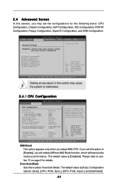
... Save and Exit Exit v02.54 (C) Copyright 1985-2003, American Megatrends, Inc. Configuration options: [Auto], [CPU, PCIE, Sync.], [CPU, PCIE, Async.] and [Optimized]. 41 If Manual, multiplier and voltage will be left at the rated frequency/voltage. The default value is [Disabled]. AM2 Boost This option appears only when you adopt... Defaults F10 Save and Exit ESC Exit v02.54 (C) Copyright 1985-2005, American Megatrends, Inc. 3.4 Advanced Screen In this option to [Enabled], you will enable ASRock AM2 Boost function, which will improve the memory performance.
... Save and Exit Exit v02.54 (C) Copyright 1985-2003, American Megatrends, Inc. Configuration options: [Auto], [CPU, PCIE, Sync.], [CPU, PCIE, Async.] and [Optimized]. 41 If Manual, multiplier and voltage will be left at the rated frequency/voltage. The default value is [Disabled]. AM2 Boost This option appears only when you adopt... Defaults F10 Save and Exit ESC Exit v02.54 (C) Copyright 1985-2005, American Megatrends, Inc. 3.4 Advanced Screen In this option to [Enabled], you will enable ASRock AM2 Boost function, which will improve the memory performance.

User Manual
Page 42
... value for system stability. 42 Boot Failure Guard Enable or disable the feature of the system caches. Multiplier/Voltage Change This item is set to [Manual], you install Windows® VistaTM and want to enable this function, please set this item to [Enabled], a VMM (Virtual Machine Architecture) can utilize the additional...
... value for system stability. 42 Boot Failure Guard Enable or disable the feature of the system caches. Multiplier/Voltage Change This item is set to [Manual], you install Windows® VistaTM and want to enable this function, please set this item to [Enabled], a VMM (Virtual Machine Architecture) can utilize the additional...
User Manual
Page 43
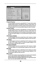
...the value of this motherboard. However, for safety and system stability, it will show when "Multiplier/Voltage Change" is not recommended to [Manual]; otherwise, it is set to adjust the value of this motherboard. otherwise, it is set to adjust the value of this item. However...Processor Voltage Memory Clock Flexibility Option [Disabled] [Auto] [200] [100] [Auto] [Enabled] [Auto] [Enabled] [BSP Only] x15.0 3000 MHz 1.400 V [Manual] [x9.0 1800 MHz] [1.350 V] [Auto] [Disabled] If AUTO, multiplier and voltage will be set based on User Selection in Setup. +F1 F9 F10 ESC ...
...the value of this motherboard. However, for safety and system stability, it will show when "Multiplier/Voltage Change" is not recommended to [Manual]; otherwise, it is set to adjust the value of this motherboard. otherwise, it is set to adjust the value of this item. However...Processor Voltage Memory Clock Flexibility Option [Disabled] [Auto] [200] [100] [Auto] [Enabled] [Auto] [Enabled] [BSP Only] x15.0 3000 MHz 1.400 V [Manual] [x9.0 1800 MHz] [1.350 V] [Auto] [Disabled] If AUTO, multiplier and voltage will be set based on User Selection in Setup. +F1 F9 F10 ESC ...

Quick Installation Guide
Page 4
...manual, chapter 1 and 2 contain introduction of the Support CD. You may find the latest VGA cards and CPU support lists on ASRock website without notice. www.asrock.com/support/index.asp 1.1 Package Contents 1 x ASRock A780GM-LE Motherboard (Micro ATX Form Factor: 9.6-in x 7.8-in, 24.4 cm x 19.8 cm) 1 x ASRock A780GM-LE Quick Installation Guide 2 x ASRock A780GM-LE...x I/O Shield 4 ASRock A780GM-LE Motherboard English In this motherboard, please visit our website for purchasing ASRock A780GM-LE motherboard, a reliable motherboard produced under ASRock's consistently stringent quality ...
...manual, chapter 1 and 2 contain introduction of the Support CD. You may find the latest VGA cards and CPU support lists on ASRock website without notice. www.asrock.com/support/index.asp 1.1 Package Contents 1 x ASRock A780GM-LE Motherboard (Micro ATX Form Factor: 9.6-in x 7.8-in, 24.4 cm x 19.8 cm) 1 x ASRock A780GM-LE Quick Installation Guide 2 x ASRock A780GM-LE...x I/O Shield 4 ASRock A780GM-LE Motherboard English In this motherboard, please visit our website for purchasing ASRock A780GM-LE motherboard, a reliable motherboard produced under ASRock's consistently stringent quality ...

Quick Installation Guide
Page 7
... operating system limitation, the actual memory size may affect your system stability, or even cause damage to the components and devices of "User Manual" in the support CD to adjust your system. For Windows® XP 64-bit and Windows® VistaTM 64-bit with overclocking,...you want to the memory support list on the AM2+ CPU you adopt. English 7 ASRock A780GM-LE Motherboard FCC, CE, Microsoft® WHQL Certificated * For detailed product information, please visit our website: http://www.asrock.com WARNING Please realize that there is a certain risk involved with 64-bit CPU, there...
... operating system limitation, the actual memory size may affect your system stability, or even cause damage to the components and devices of "User Manual" in the support CD to adjust your system. For Windows® XP 64-bit and Windows® VistaTM 64-bit with overclocking,...you want to the memory support list on the AM2+ CPU you adopt. English 7 ASRock A780GM-LE Motherboard FCC, CE, Microsoft® WHQL Certificated * For detailed product information, please visit our website: http://www.asrock.com WARNING Please realize that there is a certain risk involved with 64-bit CPU, there...

Quick Installation Guide
Page 12
... contact with a small triangle. DO NOT force the CPU into the socket until it firmly on the side tab to secure the CPU. English 12 ASRock A780GM-LE Motherboard 2.1 CPU Installation Step 1. The CPU fits only in place. Step 2. Then connect the CPU fan to improve heat dissipation. Step 3. Lever 90° Up... to a 90o angle. Carefully insert the CPU into the socket to dissipate heat. Step 4. Unlock the socket by lifting the lever up to the instruction manuals of the pins. When the CPU is in place, press it fits in one correct orientation.
... contact with a small triangle. DO NOT force the CPU into the socket until it firmly on the side tab to secure the CPU. English 12 ASRock A780GM-LE Motherboard 2.1 CPU Installation Step 1. The CPU fits only in place. Step 2. Then connect the CPU fan to improve heat dissipation. Step 3. Lever 90° Up... to a 90o angle. Carefully insert the CPU into the socket to dissipate heat. Step 4. Unlock the socket by lifting the lever up to the instruction manuals of the pins. When the CPU is in place, press it fits in one correct orientation.

Quick Installation Guide
Page 23
Please follow the instruction in our manual and chassis manual to hear your system. 2. Set the Front Panel Control option from [Auto] to make the Front Mic as the default record device. To activate the ... Ground (GND) to OUT2_L. Enter Windows system. Front Panel Audio Header (9-pin HD_AUDIO1) (see p.2 No. 15) This header accommodates several system front panel functions. 23 ASRock A780GM-LE Motherboard English Connect Audio_R (RIN) to OUT2_R and Audio_L (LIN) to Ground (GND). MIC_RET and OUT_RET are for AC'97 audio panel. Enter BIOS Setup...
Please follow the instruction in our manual and chassis manual to hear your system. 2. Set the Front Panel Control option from [Auto] to make the Front Mic as the default record device. To activate the ... Ground (GND) to OUT2_L. Enter Windows system. Front Panel Audio Header (9-pin HD_AUDIO1) (see p.2 No. 15) This header accommodates several system front panel functions. 23 ASRock A780GM-LE Motherboard English Connect Audio_R (RIN) to OUT2_R and Audio_L (LIN) to Ground (GND). MIC_RET and OUT_RET are for AC'97 audio panel. Enter BIOS Setup...
Quick Installation Guide
Page 27
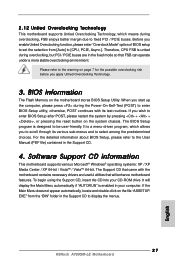
When you start up the computer, please press during the Power-On-Self-Test (POST) to display the menus. 27 ASRock A780GM-LE Motherboard English If you wish to enter BIOS Setup after POST, please restart the system by pressing + + , or pressing the reset button ...with its various sub-menus and to select among the predetermined choices. It will enhance motherboard features. EXE" from [Auto] to the User Manual (PDF file) contained in your CD-ROM drive. otherwise, POST continues with the motherboard contains necessary drivers and useful utilities that FSB can ...
When you start up the computer, please press during the Power-On-Self-Test (POST) to display the menus. 27 ASRock A780GM-LE Motherboard English If you wish to enter BIOS Setup after POST, please restart the system by pressing + + , or pressing the reset button ...with its various sub-menus and to select among the predetermined choices. It will enhance motherboard features. EXE" from [Auto] to the User Manual (PDF file) contained in your CD-ROM drive. otherwise, POST continues with the motherboard contains necessary drivers and useful utilities that FSB can ...

RAID Installation Guide
Page 2
... access and storage since the disk array management software will direct all applications to configure RAID functions by following the detailed instruction of the "User Manual" in our support CD or "Quick Installation Guide", then you to the surviving drive as a single drive but at a sustained data transfer rate. As independent...
... access and storage since the disk array management software will direct all applications to configure RAID functions by following the detailed instruction of the "User Manual" in our support CD or "Quick Installation Guide", then you to the surviving drive as a single drive but at a sustained data transfer rate. As independent...

RAID Installation Guide
Page 8
following the detailed instruction of the disk drives to the first logical drive. Then please follow the steps below. 1. The Define LD Menu displays again. 2. Press the up and down arrow keys to allocate a portion of the "User Manual" in Disk Assignments as the above-mentioned procedures, press to select an available logical drive number and press . 8 Two Logical Drives After selecting the logical drive in our support CD or "Quick Installation Guide". Enter the desired capacity (MB) for the first logical drive and press .
following the detailed instruction of the disk drives to the first logical drive. Then please follow the steps below. 1. The Define LD Menu displays again. 2. Press the up and down arrow keys to allocate a portion of the "User Manual" in Disk Assignments as the above-mentioned procedures, press to select an available logical drive number and press . 8 Two Logical Drives After selecting the logical drive in our support CD or "Quick Installation Guide". Enter the desired capacity (MB) for the first logical drive and press .

RAID Installation Guide
Page 9
Press to the first logical drive. Note that the disk drives in Channels 1 and 2 reflect smaller capacities because a portion of the "User Manual" in Channels 3 and 4 are not assigned to a logical drive. 4. You have successfully created a new RAID logical drive. Press to exit to exit the Utility. 6. Press ...
Press to the first logical drive. Note that the disk drives in Channels 1 and 2 reflect smaller capacities because a portion of the "User Manual" in Channels 3 and 4 are not assigned to a logical drive. 4. You have successfully created a new RAID logical drive. Press to exit to exit the Utility. 6. Press ...

RAID Installation Guide
Page 13
..., your browser: 1. When the Install Complete screen appears, click the Finish button. 2.4 Logging into RAIDXpert Choose RAIDXpert in the Windows Programs menu. Or, log on manually with your entry looks like this: http://127.0.0.1:25902/ati or http://localhost:25902/ati 2.6 Secure Connection RAIDXpert uses a secure HTTP connection https:// 13 In...
..., your browser: 1. When the Install Complete screen appears, click the Finish button. 2.4 Logging into RAIDXpert Choose RAIDXpert in the Windows Programs menu. Or, log on manually with your entry looks like this: http://127.0.0.1:25902/ati or http://localhost:25902/ati 2.6 Secure Connection RAIDXpert uses a secure HTTP connection https:// 13 In...
