
User Manual
Page 12
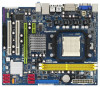
... 11 Fifth SATAII Connector (SATAII_5 (PORT 4)) (HD_AUDIO1, Lime) 12 Fourth SATAII Connector (SATAII_4 (PORT 3)) 28 Internal Audio Connector: CD1 (Black) 13 Southbridge Controller 29 PCI Slots (PCI1- 2) 14 Chassis Speaker Header 30 PCI Express 2.0 x16 Slot (PCIE2; Green) 15 System Panel... IN Center: FRONT Bottom: MIC IN LAN AUDIO CODEC PCIE1 Super I/O CD1 1 HD_AUDIO1 LPT1 1 IR1 1 FLOPPY1 AMD 780G Chipset IDE1 RoHS PCIE2 A780GM-LE PCI1 PCI2 USB10_11 1 8Mb BIOS USB8_9 1 SATAII_4 SATAII_5 SATAII_6 (PORT 3) (PORT 4) (PORT 5) AMD SB710 / SB700 Chipset SPEAKER1 1 PLED PWRBTN...
... 11 Fifth SATAII Connector (SATAII_5 (PORT 4)) (HD_AUDIO1, Lime) 12 Fourth SATAII Connector (SATAII_4 (PORT 3)) 28 Internal Audio Connector: CD1 (Black) 13 Southbridge Controller 29 PCI Slots (PCI1- 2) 14 Chassis Speaker Header 30 PCI Express 2.0 x16 Slot (PCIE2; Green) 15 System Panel... IN Center: FRONT Bottom: MIC IN LAN AUDIO CODEC PCIE1 Super I/O CD1 1 HD_AUDIO1 LPT1 1 IR1 1 FLOPPY1 AMD 780G Chipset IDE1 RoHS PCIE2 A780GM-LE PCI1 PCI2 USB10_11 1 8Mb BIOS USB8_9 1 SATAII_4 SATAII_5 SATAII_6 (PORT 3) (PORT 4) (PORT 5) AMD SB710 / SB700 Chipset SPEAKER1 1 PLED PWRBTN...

User Manual
Page 24
... permanent damage of the motherboard! • Floppy Connector (33-pin FLOPPY1) (see p.12 No. 9) PIN1 IDE1 connect the blue end to the motherboard connect the black end to the IDE devices 80-conductor ATA 66/100/133 cable Note: Please refer to Pin1 Note: Make sure the red-striped side of...
... permanent damage of the motherboard! • Floppy Connector (33-pin FLOPPY1) (see p.12 No. 9) PIN1 IDE1 connect the blue end to the motherboard connect the black end to the IDE devices 80-conductor ATA 66/100/133 cable Note: Please refer to Pin1 Note: Make sure the red-striped side of...

User Manual
Page 25
... of the power supply. Serial ATA (SATA) Power Cable (Optional) connect to the SATA HDD power connector connect to the power supply Please connect the black end of SATA power cable to the power connector on this motherboard.
... of the power supply. Serial ATA (SATA) Power Cable (Optional) connect to the SATA HDD power connector connect to the power supply Please connect the black end of SATA power cable to the power connector on this motherboard.

User Manual
Page 27
...this connector. 1 13 Though this motherboard provides 24-pin ATX power connector, 12 24 it to Pin 1-3. Though this connector and match the black wire to the ground pin. To use the 20-pin ATX power supply, please plug your power supply along with ATX 12V plug to this... CPU Fan Connector (4-pin CPU_FAN1) (see p.12 No. 6) 4 3 2 1 GND +12V CPU_FAN_SPEED FAN_SPEED_CONTROL Please connect the chassis speaker to this connector and match the black wire to the ground pin. If you adopt a traditional 20-pin ATX power supply. Please connect the CPU fan cable to do so will cause...
...this connector. 1 13 Though this motherboard provides 24-pin ATX power connector, 12 24 it to Pin 1-3. Though this connector and match the black wire to the ground pin. To use the 20-pin ATX power supply, please plug your power supply along with ATX 12V plug to this... CPU Fan Connector (4-pin CPU_FAN1) (see p.12 No. 6) 4 3 2 1 GND +12V CPU_FAN_SPEED FAN_SPEED_CONTROL Please connect the chassis speaker to this connector and match the black wire to the ground pin. If you adopt a traditional 20-pin ATX power supply. Please connect the CPU fan cable to do so will cause...

User Manual
Page 31
... data loss. 31 Please make sure the SATA / SATAII driver is available on our website: www.asrock.com 2. SATA power cable SATA 7-pin connector The SATA 15-pin power connector (Black) connect to SATA / SATAII HDD 1x4-pin conventional power connector (White) connect to use the SATA... Please follow below operation guide of our motherboard is designed only for SATA / SATAII HDD in the product spec on our support website: www.asrock.com 4. 2.12 SATA / SATAII HDD Hot Plug Feature and Operation Guide This motherboard supports Hot Plug feature for our motherboard, which supports SATA...
... data loss. 31 Please make sure the SATA / SATAII driver is available on our website: www.asrock.com 2. SATA power cable SATA 7-pin connector The SATA 15-pin power connector (Black) connect to SATA / SATAII HDD 1x4-pin conventional power connector (White) connect to use the SATA... Please follow below operation guide of our motherboard is designed only for SATA / SATAII HDD in the product spec on our support website: www.asrock.com 4. 2.12 SATA / SATAII HDD Hot Plug Feature and Operation Guide This motherboard supports Hot Plug feature for our motherboard, which supports SATA...

User Manual
Page 32
... side. 32 SATA power cable 1x4-pin power connector (White) Step 3 Connect SATA 15-pin power cable connector (Black) end to the SATA / SATAII HDD. Step 2 Unplug SATA 15-pin power cable connector (Black) from SATA / SATAII HDD side. Step 1 Please connect SATA power cable 1x4-pin end Step 2 Connect SATA data...
... side. 32 SATA power cable 1x4-pin power connector (White) Step 3 Connect SATA 15-pin power cable connector (Black) end to the SATA / SATAII HDD. Step 2 Unplug SATA 15-pin power cable connector (Black) from SATA / SATAII HDD side. Step 1 Please connect SATA power cable 1x4-pin end Step 2 Connect SATA data...

Quick Installation Guide
Page 2
... Audio Connector: CD1 (Black) 13 Southbridge Controller 29 PCI Slots (PCI1- 2) 14 Chassis Speaker Header 30 PCI Express 2.0 x16 Slot (PCIE2; Green) 15 System Panel Header (PANEL1, Orange) 32 Northbridge Controller 16 Third SATAII Connector (SATAII_3 (PORT 2)) 33 Serial Port Connector (COM1) 17 Secondary SATAII Connector (SATAII_2 (PORT 1)) 2 ASRock A780GM-LE Motherboard Green) (SPEAKER...
... Audio Connector: CD1 (Black) 13 Southbridge Controller 29 PCI Slots (PCI1- 2) 14 Chassis Speaker Header 30 PCI Express 2.0 x16 Slot (PCIE2; Green) 15 System Panel Header (PANEL1, Orange) 32 Northbridge Controller 16 Third SATAII Connector (SATAII_3 (PORT 2)) 33 Serial Port Connector (COM1) 17 Secondary SATAII Connector (SATAII_2 (PORT 1)) 2 ASRock A780GM-LE Motherboard Green) (SPEAKER...

Quick Installation Guide
Page 21
... p.2 No. 9) connect the blue end to the motherboard connect the black end to the IDE devices 80-conductor ATA 66/100/133 cable Note: Please refer to the SATA / SATAII hard disk or the SATAII connector on the motherboard. English 21 ASRock A780GM-LE Motherboard Do NOT place jumper caps over the headers and...
... p.2 No. 9) connect the blue end to the motherboard connect the black end to the IDE devices 80-conductor ATA 66/100/133 cable Note: Please refer to the SATA / SATAII hard disk or the SATAII connector on the motherboard. English 21 ASRock A780GM-LE Motherboard Do NOT place jumper caps over the headers and...

Quick Installation Guide
Page 22
... USB10_11) (see p.2 No. 23) (9-pin USB8_9) (see p.2 No. 22) Please connect the black end of SATA power cable to receive stereo audio input from sound sources such as a CD-ROM, DVD-ROM, TV tuner card, or MPEG card. 22 ASRock A780GM-LE Motherboard Each USB 2.0 header can support two USB 2.0 ports. (9-pin USB6_7) (see...
... USB10_11) (see p.2 No. 23) (9-pin USB8_9) (see p.2 No. 22) Please connect the black end of SATA power cable to receive stereo audio input from sound sources such as a CD-ROM, DVD-ROM, TV tuner card, or MPEG card. 22 ASRock A780GM-LE Motherboard Each USB 2.0 header can support two USB 2.0 ports. (9-pin USB6_7) (see...

Quick Installation Guide
Page 24
...If you adopt a traditional 20-pin ATX power supply. Failing to do so will cause power up failure. Though this connector and match the black wire to the ground pin. To use the 20-pin ATX power supply, please plug your power supply along with ATX 12V plug to this... provides 4-Pin CPU fan (Quiet Fan) support, the 3-Pin CPU fan still can still work successfully even without the fan speed control function. English 24 ASRock A780GM-LE Motherboard ATX 12V Power Connector (4-pin ATX12V1) (see p.2 No. 1) Serial port Header (9-pin COM1) (see p.2 No.33) 20-Pin ATX Power Supply Installation 1...
...If you adopt a traditional 20-pin ATX power supply. Failing to do so will cause power up failure. Though this connector and match the black wire to the ground pin. To use the 20-pin ATX power supply, please plug your power supply along with ATX 12V plug to this... provides 4-Pin CPU fan (Quiet Fan) support, the 3-Pin CPU fan still can still work successfully even without the fan speed control function. English 24 ASRock A780GM-LE Motherboard ATX 12V Power Connector (4-pin ATX12V1) (see p.2 No. 1) Serial port Header (9-pin COM1) (see p.2 No.33) 20-Pin ATX Power Supply Installation 1...

RAID Installation Guide
Page 15
... Drive Size field. If you want to select them. In the Select Drive Type screen, click the following option: • Free Drives - Selected drives have a black frame. 4. Available drives have a red frame. For RAID Ready, select only one physical drive. 15 Click the Next button. 6.
... Drive Size field. If you want to select them. In the Select Drive Type screen, click the following option: • Free Drives - Selected drives have a black frame. 4. Available drives have a red frame. For RAID Ready, select only one physical drive. 15 Click the Next button. 6.
