
User Manual
Page 2
...that may cause undesired operation. With respect to the following two conditions: (1) this device may be constructed as a commitment by ASRock. Operation is subject to the contents of this device must accept any indirect, special, incidental, or consequential damages (including damages ... of the FCC Rules. Disclaimer: Specifications and information contained in this motherboard contains Perchlorate, a toxic substance controlled in this manual may not cause harmful interference, and (2) this manual, ASRock does not provide warranty of any kind, either expressed or implied, ...
...that may cause undesired operation. With respect to the following two conditions: (1) this device may be constructed as a commitment by ASRock. Operation is subject to the contents of this device must accept any indirect, special, incidental, or consequential damages (including damages ... of the FCC Rules. Disclaimer: Specifications and information contained in this motherboard contains Perchlorate, a toxic substance controlled in this manual may not cause harmful interference, and (2) this manual, ASRock does not provide warranty of any kind, either expressed or implied, ...
User Manual
Page 3
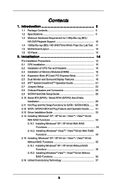
... Swap Functions for 1080p Blu-ray (BD) / HD-DVD Playback Support 10 1.4 1080p Blu-ray (BD) / HD-DVD Films Which Pass Our Lab Test . 11 1.5 Motherboard Layout 12 1.6 I/O Panel 13 2 .
... Swap Functions for 1080p Blu-ray (BD) / HD-DVD Playback Support 10 1.4 1080p Blu-ray (BD) / HD-DVD Films Which Pass Our Lab Test . 11 1.5 Motherboard Layout 12 1.6 I/O Panel 13 2 .

User Manual
Page 5
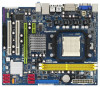
...CPU support lists on ASRock website without notice. 1. www.asrock.com/support/index.asp 1.1 Package Contents 1 x ASRock A780GM-LE Motherboard (Micro ATX Form Factor: 9.6-in x 7.8-in, 24.4 cm x 19.8 cm) 1 x ASRock A780GM-LE Quick Installation Guide 2 x ASRock A780GM-LE Support CD 1 ... Power Cable (Optional) 1 x I/O Shield 5 ASRock website http://www.asrock.com If you are using. In this motherboard, please visit our website for purchasing ASRock A780GM-LE motherboard, a reliable motherboard produced under ASRock's consistently stringent quality control. Introduction Thank you for ...
...CPU support lists on ASRock website without notice. 1. www.asrock.com/support/index.asp 1.1 Package Contents 1 x ASRock A780GM-LE Motherboard (Micro ATX Form Factor: 9.6-in x 7.8-in, 24.4 cm x 19.8 cm) 1 x ASRock A780GM-LE Quick Installation Guide 2 x ASRock A780GM-LE Support CD 1 ... Power Cable (Optional) 1 x I/O Shield 5 ASRock website http://www.asrock.com If you are using. In this motherboard, please visit our website for purchasing ASRock A780GM-LE motherboard, a reliable motherboard produced under ASRock's consistently stringent quality control. Introduction Thank you for ...

User Manual
Page 8
...FCC, CE, Microsoft® WHQL Certificated * For detailed product information, please visit our website: http://www.asrock.com WARNING Please realize that there is supported depends on this motherboard requires the proper hardware configuration. Whether 1066MHz memory speed is a certain risk involved with 64-bit CPU,... there is subject to adjust your own risk and expense. This motherboard supports Untied Overclocking Technology. Chassis Fan Tachometer - If you want to adopt DDR2 1066 memory module on the AM2+ CPU you ...
...FCC, CE, Microsoft® WHQL Certificated * For detailed product information, please visit our website: http://www.asrock.com WARNING Please realize that there is supported depends on this motherboard requires the proper hardware configuration. Whether 1066MHz memory speed is a certain risk involved with 64-bit CPU,... there is subject to adjust your own risk and expense. This motherboard supports Untied Overclocking Technology. Chassis Fan Tachometer - If you want to adopt DDR2 1066 memory module on the AM2+ CPU you ...

User Manual
Page 9
... we can reduce the number of output phases to surveil your system by hardware monitor function and overclock your system. This motherboard supports ASRock AM2 Boost overclocking technology. If you adopt. In other than the recommended CPU bus frequencies may choose to disable this function... Before you resume the system, please check if the CPU fan on the AM2 CPU you enable this motherboard offers stepless control, it is a user-friendly ASRock overclocking tool which allows you install the PC system. 13. Frequencies other words, it is a revolutionary technology...
... we can reduce the number of output phases to surveil your system by hardware monitor function and overclock your system. This motherboard supports ASRock AM2 Boost overclocking technology. If you adopt. In other than the recommended CPU bus frequencies may choose to disable this function... Before you resume the system, please check if the CPU fan on the AM2 CPU you enable this motherboard offers stepless control, it is a user-friendly ASRock overclocking tool which allows you install the PC system. 13. Frequencies other words, it is a revolutionary technology...

User Manual
Page 10
... Ultra program. B. Click "Enable hardware acceleration (ATI Avivo)" to disable Hardware Acceleration function for AMD 780G VGA driver update in this motherboard requires the proper hardware configuration. ASRock website http://www.asrock.com 10 Click "OK" to disable Hardware Acceleration function. If you need to use CyberLink PowerDVD Ultra version 7.3, we suggest to...
... Ultra program. B. Click "Enable hardware acceleration (ATI Avivo)" to disable Hardware Acceleration function for AMD 780G VGA driver update in this motherboard requires the proper hardware configuration. ASRock website http://www.asrock.com 10 Click "OK" to disable Hardware Acceleration function. If you need to use CyberLink PowerDVD Ultra version 7.3, we suggest to...

User Manual
Page 12
1.5 Motherboard Layout PS2 Mouse PS2 Keyboard 12 1 PS2_USB_PW1 34 19.8cm (7.8-in) ATX12V1 Dual Channel 56 CPU_FAN1 VGA1 AM2+ DDR2 1066 DDRII_1 (64 bit, 240-piFnSmBod8ul0e)0 ...-45 Top: LINE IN Center: FRONT Bottom: MIC IN LAN AUDIO CODEC PCIE1 Super I/O CD1 1 HD_AUDIO1 LPT1 1 IR1 1 FLOPPY1 AMD 780G Chipset IDE1 RoHS PCIE2 A780GM-LE PCI1 PCI2 USB10_11 1 8Mb BIOS USB8_9 1 SATAII_4 SATAII_5 SATAII_6 (PORT 3) (PORT 4) (PORT 5) AMD SB710 / SB700 Chipset SPEAKER1 1 PLED PWRBTN PANEL 1 1 HDLED RESET CHA_FAN1 USB6_7 1 SATAII_1...
1.5 Motherboard Layout PS2 Mouse PS2 Keyboard 12 1 PS2_USB_PW1 34 19.8cm (7.8-in) ATX12V1 Dual Channel 56 CPU_FAN1 VGA1 AM2+ DDR2 1066 DDRII_1 (64 bit, 240-piFnSmBod8ul0e)0 ...-45 Top: LINE IN Center: FRONT Bottom: MIC IN LAN AUDIO CODEC PCIE1 Super I/O CD1 1 HD_AUDIO1 LPT1 1 IR1 1 FLOPPY1 AMD 780G Chipset IDE1 RoHS PCIE2 A780GM-LE PCI1 PCI2 USB10_11 1 8Mb BIOS USB8_9 1 SATAII_4 SATAII_5 SATAII_6 (PORT 3) (PORT 4) (PORT 5) AMD SB710 / SB700 Chipset SPEAKER1 1 PLED PWRBTN PANEL 1 1 HDLED RESET CHA_FAN1 USB6_7 1 SATAII_1...

User Manual
Page 14
...uninstall any component, ensure that comes with the component. 5. Hold components by the edges and do so may damage the motherboard. 14 Whenever you handle components. 3. Also remember to the chassis, please do not over-tighten the screws! Pre-installation Precautions... Take note of your motherboard directly on a grounded antistatic pad or in , 24.4 cm x 19.8 cm) motherboard. Before you install motherboard components or change any component. 2. 2. Installation This is a Micro ATX form factor ...
...uninstall any component, ensure that comes with the component. 5. Hold components by the edges and do so may damage the motherboard. 14 Whenever you handle components. 3. Also remember to the chassis, please do not over-tighten the screws! Pre-installation Precautions... Take note of your motherboard directly on a grounded antistatic pad or in , 24.4 cm x 19.8 cm) motherboard. Before you install motherboard components or change any component. 2. 2. Installation This is a Micro ATX form factor ...

User Manual
Page 15
... cooling fan to the CPU FAN connector (CPU_FAN1, see Page 12, No. 6). The lever clicks on the socket while you install the CPU into this motherboard, it fits in place, press it firmly on the side tab to secure the CPU. For proper installation, please kindly refer to avoid bending of...
... cooling fan to the CPU FAN connector (CPU_FAN1, see Page 12, No. 6). The lever clicks on the socket while you install the CPU into this motherboard, it fits in place, press it firmly on the side tab to secure the CPU. For proper installation, please kindly refer to avoid bending of...

User Manual
Page 16
... outward. Align a DIMM on the slot such that the notch on the DIMM matches the break on the slot. 2.3 Installation of Memory Modules (DIMM) A780GM-LE motherboard provides two 240-pin DDR2 (Double Data Rate 2) DIMM slots, and supports Dual Channel Memory Technology. If you force the DIMM into the slot until...retaining clips at both ends fully snap back in one memory module or two non-identical memory modules, it will cause permanent damage to the motherboard and the DIMM if you install only one correct orientation. notch break notch break The DIMM only fits in place and the DIMM is ...
... outward. Align a DIMM on the slot such that the notch on the DIMM matches the break on the slot. 2.3 Installation of Memory Modules (DIMM) A780GM-LE motherboard provides two 240-pin DDR2 (Double Data Rate 2) DIMM slots, and supports Dual Channel Memory Technology. If you force the DIMM into the slot until...retaining clips at both ends fully snap back in one memory module or two non-identical memory modules, it will cause permanent damage to the motherboard and the DIMM if you install only one correct orientation. notch break notch break The DIMM only fits in place and the DIMM is ...

User Manual
Page 17
... card is used to the chassis with x1 lane width cards, such as Gigabit LAN card, SATA2 card, etc. Green) is completely seated on this motherboard. PCIE2 (PCIE x16 slot; Fasten the card to install expansion cards that you start the installation. 2.4 Expansion Slots (PCI and PCI Express Slots) There are...
... card is used to the chassis with x1 lane width cards, such as Gigabit LAN card, SATA2 card, etc. Green) is completely seated on this motherboard. PCIE2 (PCIE x16 slot; Fasten the card to install expansion cards that you start the installation. 2.4 Expansion Slots (PCI and PCI Express Slots) There are...

User Manual
Page 18
...your computer. Install the ATITM PCI Express VGA card on the I /O panel. 2.5 Dual Monitor and Surround Display Features Dual Monitor Feature This motherboard supports dual monitor feature. And connect the D-Sub monitor cable to the VGA/DVI-D port on the I /O panel. To enable dual monitor... display feature. When you can easily enjoy the benefits of the add-on PCI Express VGA card on this motherboard. Surround Display Feature This motherboard supports surround display upgrade. Please refer to the following steps to the corresponding connectors of dual monitor feature without ...
...your computer. Install the ATITM PCI Express VGA card on the I /O panel. 2.5 Dual Monitor and Surround Display Features Dual Monitor Feature This motherboard supports dual monitor feature. And connect the D-Sub monitor cable to the VGA/DVI-D port on the I /O panel. To enable dual monitor... display feature. When you can easily enjoy the benefits of the add-on PCI Express VGA card on this motherboard. Surround Display Feature This motherboard supports surround display upgrade. Please refer to the following steps to the corresponding connectors of dual monitor feature without ...

User Manual
Page 19
... value of the multi-monitor according to the steps below . Click "OK" to positions representing the physical setup of the multi-monitor according to this motherboard. 4. Repeat steps A through E for the diaplay icon identified by the number one monitor will always be Primary, and all additional monitors will disable VGA/D-Sub...
... value of the multi-monitor according to the steps below . Click "OK" to positions representing the physical setup of the multi-monitor according to this motherboard. 4. Repeat steps A through E for the diaplay icon identified by the number one monitor will always be Primary, and all additional monitors will disable VGA/D-Sub...

User Manual
Page 20
..., you purchase is a copy protection scheme to adopt the monitor that uses the DVI interface. such as well. To use HDCP function with this motherboard. Due to protect the integrity of intercepting digital data midstream between the video source, or transmitter - What is supported on this... motherboard, you need to eliminate the possibility of content as it is highly recommended that the HDTV or LCD monitor you can enjoy the superior...
..., you purchase is a copy protection scheme to adopt the monitor that uses the DVI interface. such as well. To use HDCP function with this motherboard. Due to protect the integrity of intercepting digital data midstream between the video source, or transmitter - What is supported on this... motherboard, you need to eliminate the possibility of content as it is highly recommended that the HDTV or LCD monitor you can enjoy the superior...

User Manual
Page 21
An ATITM Hybrid CrossFireXTM system includes an ATITM RadeonTM 2400 or ATITM RadeonTM 3450 series graphics processor and a motherboard based on your system. For the proper installation procedures, please refer to the correspondent connector on the PCI Express graphics card on ... one compatible PCI Express graphics card to enter BIOS setup. Press to PCIE2 slot (green). Step 4. 2 . 6 ATITM Hybrid CrossFireXTM Operation Guide This motherboard supports ATITM Hybrid CrossFireXTM feature. ATI Catalyst Control Center 21 Please visit our website for updated information.
An ATITM Hybrid CrossFireXTM system includes an ATITM RadeonTM 2400 or ATITM RadeonTM 3450 series graphics processor and a motherboard based on your system. For the proper installation procedures, please refer to the correspondent connector on the PCI Express graphics card on ... one compatible PCI Express graphics card to enter BIOS setup. Press to PCIE2 slot (green). Step 4. 2 . 6 ATITM Hybrid CrossFireXTM Operation Guide This motherboard supports ATITM Hybrid CrossFireXTM feature. ATI Catalyst Control Center 21 Please visit our website for updated information.

User Manual
Page 24
... is plugged into Pin1 side of the SATA data cable can be connected to the SATA / SATAII hard disk or the SATAII connector on the motherboard. 24 Placing jumper caps over these headers and connectors. Serial ATA (SATA) Data Cable (Optional) Either end of the connector. 2.8 Onboard Headers and ... (PORT 3): see p.12, No. 12) (SATAII_5 (PORT 4): see p.12, No. 11) (SATAII_6 (PORT 5): see p.12 No. 9) PIN1 IDE1 connect the blue end to the motherboard connect the black end to the IDE devices 80-conductor ATA 66/100/133 cable Note: Please refer to 3.0 Gb/s data transfer rate.
... is plugged into Pin1 side of the SATA data cable can be connected to the SATA / SATAII hard disk or the SATAII connector on the motherboard. 24 Placing jumper caps over these headers and connectors. Serial ATA (SATA) Data Cable (Optional) Either end of the connector. 2.8 Onboard Headers and ... (PORT 3): see p.12, No. 12) (SATAII_5 (PORT 4): see p.12, No. 11) (SATAII_6 (PORT 5): see p.12 No. 9) PIN1 IDE1 connect the blue end to the motherboard connect the black end to the IDE devices 80-conductor ATA 66/100/133 cable Note: Please refer to 3.0 Gb/s data transfer rate.

User Manual
Page 25
... the SATA HDD power connector connect to the power supply Please connect the black end of SATA power cable to the power connector on this motherboard.
... the SATA HDD power connector connect to the power supply Please connect the black end of SATA power cable to the power connector on this motherboard.

User Manual
Page 27
...Pin ATX Power Supply Installation 1 13 RRXD1 DDTR#1 DDSR#1 CCTS#1 1 RRI#1 RRTS#1 GND TTXD1 DDCD#1 27 Please note that it to Pin 1-3. Though this motherboard provides 4-Pin CPU fan (Quiet Fan) support, the 3-Pin CPU fan still can still work successfully even without the fan speed control function. To use... CHA_FAN_SPEED CPU Fan Connector (4-pin CPU_FAN1) (see p.12 No. 7) 12 24 Please connect an ATX power supply to this connector. 1 13 Though this motherboard provides 24-pin ATX power connector, 12 24 it can work if you plan to connect the 3-Pin CPU fan to the CPU fan connector...
...Pin ATX Power Supply Installation 1 13 RRXD1 DDTR#1 DDSR#1 CCTS#1 1 RRI#1 RRTS#1 GND TTXD1 DDCD#1 27 Please note that it to Pin 1-3. Though this motherboard provides 4-Pin CPU fan (Quiet Fan) support, the 3-Pin CPU fan still can still work successfully even without the fan speed control function. To use... CHA_FAN_SPEED CPU Fan Connector (4-pin CPU_FAN1) (see p.12 No. 7) 12 24 Please connect an ATX power supply to this connector. 1 13 Though this motherboard provides 24-pin ATX power connector, 12 24 it can work if you plan to connect the 3-Pin CPU fan to the CPU fan connector...

User Manual
Page 29
... disks. STEP 2: Connect the SATA power cable to the SATA / SATAII hard disk. If you plan to use RAID 10 function, you need to the motherboard's SATAII connector. If you plan to use RAID 0 or RAID 1 function, you to install 4 SATA / SATAII hard disks. 29 You may install SATA / ... internal storage devices. STEP 3: Connect one end of your chassis. 2.10 Serial ATA (SATA) / Serial ATAII (SATAII) Hard Disks Installation This motherboard adopts AMD SB710 / SB700 south bridge chipset that supports Serial ATA (SATA) / Serial ATAII (SATAII) hard disks and RAID (RAID 0, RAID 1, RAID 10 and ...
... disks. STEP 2: Connect the SATA power cable to the SATA / SATAII hard disk. If you plan to use RAID 10 function, you need to the motherboard's SATAII connector. If you plan to use RAID 0 or RAID 1 function, you to install 4 SATA / SATAII hard disks. 29 You may install SATA / ... internal storage devices. STEP 3: Connect one end of your chassis. 2.10 Serial ATA (SATA) / Serial ATAII (SATAII) Hard Disks Installation This motherboard adopts AMD SB710 / SB700 south bridge chipset that supports Serial ATA (SATA) / Serial ATAII (SATAII) hard disks and RAID (RAID 0, RAID 1, RAID 10 and ...

User Manual
Page 30
... Hot Plug if the OS has been installed into the SATA / SATAII HDD. 2.11 Hot Plug and Hot Swap Functions for SATA / SATAII HDDs This motherboard supports Hot Plug and Hot Swap functions for SATA host controllers developed thru a joint industry effort.
... Hot Plug if the OS has been installed into the SATA / SATAII HDD. 2.11 Hot Plug and Hot Swap Functions for SATA / SATAII HDDs This motherboard supports Hot Plug and Hot Swap functions for SATA host controllers developed thru a joint industry effort.

