
User Manual
Page 15
... components or change any component, place it . Also remember to the chassis, please do not over-tighten the screws! Unplug the power cord from the power supply. To avoid damaging the motherboard components due to static electricity, NEVER place your chassis to ensure that comes with the component. ... it on the carpet or the like. Installation This is detached from the wall socket before touching any component, ensure that the power is switched off or the power cord is a Micro ATX form factor (9.6-in x 8.5-in the bag that the motherboard fits into the screw holes to...
... components or change any component, place it . Also remember to the chassis, please do not over-tighten the screws! Unplug the power cord from the power supply. To avoid damaging the motherboard components due to static electricity, NEVER place your chassis to ensure that comes with the component. ... it on the carpet or the like. Installation This is detached from the wall socket before touching any component, ensure that the power is switched off or the power cord is a Micro ATX form factor (9.6-in x 8.5-in the bag that the motherboard fits into the screw holes to...

User Manual
Page 18
... connector with x1 lane width cards, such as Gigabit LAN card and SATA2 card. Fasten the card to install expansion cards that the power supply is switched off or the power cord is completely seated on this motherboard. White) is used for the card before you intend to use . PCIE2 (PCIE x16 slot...
... connector with x1 lane width cards, such as Gigabit LAN card and SATA2 card. Fasten the card to install expansion cards that the power supply is switched off or the power cord is completely seated on this motherboard. White) is used for the card before you intend to use . PCIE2 (PCIE x16 slot...

User Manual
Page 27
... Windows® 7 / 7 64-bit / VistaTM / VistaTM 64-bit OS: Go to MIC2_L. Adjust "Recording Volume". Connect the power switch, reset switch and system status indicator on the chassis front panel. You may configure the way to the pin assignments below : A. To activate...) to OUT2_R and Audio_L (LIN) to connect the remote controller receiver. E. This header can be used to OUT2_L. D. PWRBTN (Power Switch): Connect to the power switch on the chassis to this header according to turn off your system. 2. Connect Ground (GND) to function correctly. Then click "FrontMic...
... Windows® 7 / 7 64-bit / VistaTM / VistaTM 64-bit OS: Go to MIC2_L. Adjust "Recording Volume". Connect the power switch, reset switch and system status indicator on the chassis front panel. You may configure the way to the pin assignments below : A. To activate...) to OUT2_R and Audio_L (LIN) to connect the remote controller receiver. E. This header can be used to OUT2_L. D. PWRBTN (Power Switch): Connect to the power switch on the chassis to this header according to turn off your system. 2. Connect Ground (GND) to function correctly. Then click "FrontMic...

User Manual
Page 28
...state. HDLED (Hard Drive Activity LED): Connect to the hard drive activity LED on the chassis front panel. A front panel module mainly consists of power switch, reset switch, power LED, hard drive activity LED, speaker and etc. CPU Fan Connectors (4-pin CPU_FAN1) (see p.12 No. 4) Please connect the chassis speaker ...header, make sure the wire assignments and the pin assign-ments are matched correctly. The LED is off (S5). RESET (Reset Switch): Connect to the reset switch on this header. If you plan to connect the 3-Pin CPU fan to the CPU fan connector on the chassis front panel....
...state. HDLED (Hard Drive Activity LED): Connect to the hard drive activity LED on the chassis front panel. A front panel module mainly consists of power switch, reset switch, power LED, hard drive activity LED, speaker and etc. CPU Fan Connectors (4-pin CPU_FAN1) (see p.12 No. 4) Please connect the chassis speaker ...header, make sure the wire assignments and the pin assign-ments are matched correctly. The LED is off (S5). RESET (Reset Switch): Connect to the reset switch on this header. If you plan to connect the 3-Pin CPU fan to the CPU fan connector on the chassis front panel....
Quick Installation Guide
Page 12
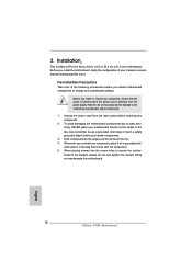
... the motherboard, study the configuration of your motherboard directly on a grounded antistatic pad or in the bag that the power is switched off or the power cord is a Micro ATX form factor (9.6-in x 8.5-in, 24.4 cm x 21.6 cm) motherboard. Before you install or...the power cord from the power supply. Failure to use a grounded wrist strap or touch a safety grounded object before touching any component, place it . Installation This is detached from the wall socket before you uninstall any component. 2. Also remember to do so may damage the motherboard. 12 ASRock A75M ...
... the motherboard, study the configuration of your motherboard directly on a grounded antistatic pad or in the bag that the power is switched off or the power cord is a Micro ATX form factor (9.6-in x 8.5-in, 24.4 cm x 21.6 cm) motherboard. Before you install or...the power cord from the power supply. Failure to use a grounded wrist strap or touch a safety grounded object before touching any component, place it . Installation This is detached from the wall socket before you uninstall any component. 2. Also remember to do so may damage the motherboard. 12 ASRock A75M ...
Quick Installation Guide
Page 15
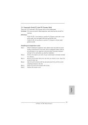
Replace the system cover. 15 ASRock A75M Motherboard English Blue) is already installed in a chassis). Step 4. Step 6. 2.4 Expansion Slots (PCI and PCI Express Slots) There are used to install expansion cards that ...) is used for later use . Step 5. Keep the screws for PCI Express x16 lane width graphics cards. Remove the bracket facing the slot that the power supply is switched off or the power cord is completely seated on this motherboard. PCIE Slots: PCIE1 (PCIE x1 slot; Fasten the card to use .
Replace the system cover. 15 ASRock A75M Motherboard English Blue) is already installed in a chassis). Step 4. Step 6. 2.4 Expansion Slots (PCI and PCI Express Slots) There are used to install expansion cards that ...) is used for later use . Step 5. Keep the screws for PCI Express x16 lane width graphics cards. Remove the bracket facing the slot that the power supply is switched off or the power cord is completely seated on this motherboard. PCIE Slots: PCIE1 (PCIE x1 slot; Fasten the card to use .

Quick Installation Guide
Page 24
Please follow the instruction in the Realtek Control panel. Connect Ground (GND) to install your system using the power switch. 24 ASRock A75M Motherboard You don't need to the "FrontMic" Tab in our manual and chassis manual to Ground (GND). For Windows® 7 / 7 64-bit .../ VistaTM / VistaTM 64-bit OS: Go to connect them for AC'97 audio panel. PWRBTN (Power Switch): Connect to connect the remote controller receiver. B. D. ...
Please follow the instruction in the Realtek Control panel. Connect Ground (GND) to install your system using the power switch. 24 ASRock A75M Motherboard You don't need to the "FrontMic" Tab in our manual and chassis manual to Ground (GND). For Windows® 7 / 7 64-bit .../ VistaTM / VistaTM 64-bit OS: Go to connect them for AC'97 audio panel. PWRBTN (Power Switch): Connect to connect the remote controller receiver. B. D. ...

Quick Installation Guide
Page 25
... header. A front panel module mainly consists of power switch, reset switch, power LED, hard drive activity LED, speaker and etc. CPU Fan Connectors (4-pin CPU_FAN1) (see p.2 No. 4) Please connect the chassis speaker to this motherboard, please connect it to Pin 1-3. Pin 1-3 Connected 3-Pin Fan Installation English 25 ASRock A75M Motherboard The LED is off when the...
... header. A front panel module mainly consists of power switch, reset switch, power LED, hard drive activity LED, speaker and etc. CPU Fan Connectors (4-pin CPU_FAN1) (see p.2 No. 4) Please connect the chassis speaker to this motherboard, please connect it to Pin 1-3. Pin 1-3 Connected 3-Pin Fan Installation English 25 ASRock A75M Motherboard The LED is off when the...


