User Manual
Page 1
All rights reserved. 1 A55M-HVS User Manual Version 1.0 Published August 2011 Copyright©2011 ASRock INC.
All rights reserved. 1 A55M-HVS User Manual Version 1.0 Published August 2011 Copyright©2011 ASRock INC.
User Manual
Page 2
... or omissions that may cause undesired operation. Copyright Notice: No part of this manual may be reproduced, transcribed, transmitted, or translated in any language, in advance. ASRock assumes no event shall ASRock, its directors, of cers, employees, or agents be liable for any indirect,...interference received, including interference that may apply, see www.dtsc.ca.gov/hazardouswaste/perchlorate" ASRock Website: http://www.asrock.com 2 With respect to the contents of this manual are furnished for informational use only and subject to change without written consent of their respective...
... or omissions that may cause undesired operation. Copyright Notice: No part of this manual may be reproduced, transcribed, transmitted, or translated in any language, in advance. ASRock assumes no event shall ASRock, its directors, of cers, employees, or agents be liable for any indirect,...interference received, including interference that may apply, see www.dtsc.ca.gov/hazardouswaste/perchlorate" ASRock Website: http://www.asrock.com 2 With respect to the contents of this manual are furnished for informational use only and subject to change without written consent of their respective...
User Manual
Page 5
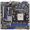
... the motherboard and stepby-step guide to this manual occur, the updated version will be updated, the content of this manual, chapter 1 and 2 contain introduction of the Support CD. www.asrock.com/support/index.asp 1.1 Package Contents ASRock A55M-HVS Motherboard (Micro ATX Form Factor: 8.9-in ... might be subject to the "User Manual" in our support CD for purchasing ASRock A55M-HVS motherboard, a reliable motherboard produced under ASRock's consistently stringent quality control. You may nd the latest VGA cards and CPU support lists on ASRock website without notice. 1. It delivers ...
... the motherboard and stepby-step guide to this manual occur, the updated version will be updated, the content of this manual, chapter 1 and 2 contain introduction of the Support CD. www.asrock.com/support/index.asp 1.1 Package Contents ASRock A55M-HVS Motherboard (Micro ATX Form Factor: 8.9-in ... might be subject to the "User Manual" in our support CD for purchasing ASRock A55M-HVS motherboard, a reliable motherboard produced under ASRock's consistently stringent quality control. You may nd the latest VGA cards and CPU support lists on ASRock website without notice. 1. It delivers ...
User Manual
Page 14
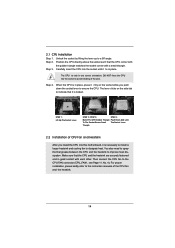
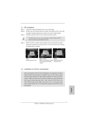
... connect the CPU fan to improve heat dissipation. Step 2. The CPU ts only in place, press it rmly on the side tab to the instruction manuals of the pins. You also need to spray thermal grease between the CPU and the heatsink to the CPU FAN connector (CPU_FAN1, see Page 11...
... connect the CPU fan to improve heat dissipation. Step 2. The CPU ts only in place, press it rmly on the side tab to the instruction manuals of the pins. You also need to spray thermal grease between the CPU and the heatsink to the CPU FAN connector (CPU_FAN1, see Page 11...

User Manual
Page 25
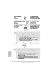
.... RESET (Reset Switch): Connect to the reset switch on the chassis to this header according to function correctly. Please follow the instruction in our manual and chassis manual to connect them for the front panel audio cable that allows convenient connection and control of audio devices. 1. You don't need to install your...
.... RESET (Reset Switch): Connect to the reset switch on the chassis to this header according to function correctly. Please follow the instruction in our manual and chassis manual to connect them for the front panel audio cable that allows convenient connection and control of audio devices. 1. You don't need to install your...
User Manual
Page 29
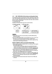
...pin power connector interface A. Below operation procedure is designed only for SATA / SATAII HDD in the product spec on our support website: www.asrock.com 4. Please follow below operation guide of attention, before you process the SATA / SATAII HDD Hot Plug, please check below cable accessories... from your dealer or HDD user manual. 2.12 SATA / SATAII HDD Hot Plug Feature and Operation Guide This motherboard supports Hot Plug feature for our motherboard, which are from...
...pin power connector interface A. Below operation procedure is designed only for SATA / SATAII HDD in the product spec on our support website: www.asrock.com 4. Please follow below operation guide of attention, before you process the SATA / SATAII HDD Hot Plug, please check below cable accessories... from your dealer or HDD user manual. 2.12 SATA / SATAII HDD Hot Plug Feature and Operation Guide This motherboard supports Hot Plug feature for our motherboard, which are from...
User Manual
Page 37
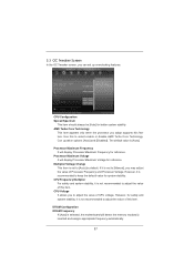
... CPU voltage. CPU Configuration Spread Spectrum This item should always be [Auto] for system stability. Multiplier/Voltage Change This item is set to [Manual], you adopt supports this item. However, it is recommended to select enable or disable AMD Turbo Core Technology. Use this item. Processor Maximum Frequency It...
... CPU voltage. CPU Configuration Spread Spectrum This item should always be [Auto] for system stability. Multiplier/Voltage Change This item is set to [Manual], you adopt supports this item. However, it is recommended to select enable or disable AMD Turbo Core Technology. Use this item. Processor Maximum Frequency It...
User Manual
Page 38
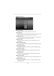
...) Use this item to enable or disable DDR power down mode. Write Recovery Time (tWR) Use this item to change RAS# Active Time (tRAS) Auto/Manual setting. Con guration options: [Disabled], [Auto]. RAS# Active Time (tRAS) Use this item to change Write Recovery Time (tWR) Auto... [Auto]. The default is [Auto]. CAS# Latency (tCL) Use this item to change Row Precharge Time (tRP) Auto/Manual setting. Row Precharge Time (tRP) Use this item to change CAS# Latency (tCL) Auto/Manual setting. Channel Interleaving It allows you to be spread out over banks on the same node, or accross...
...) Use this item to enable or disable DDR power down mode. Write Recovery Time (tWR) Use this item to change RAS# Active Time (tRAS) Auto/Manual setting. Con guration options: [Disabled], [Auto]. RAS# Active Time (tRAS) Use this item to change Write Recovery Time (tWR) Auto... [Auto]. The default is [Auto]. CAS# Latency (tCL) Use this item to change Row Precharge Time (tRP) Auto/Manual setting. Row Precharge Time (tRP) Use this item to change CAS# Latency (tCL) Auto/Manual setting. Channel Interleaving It allows you to be spread out over banks on the same node, or accross...
User Manual
Page 39
... to your own requirements. 39 The default is [Auto]. Read to Precharge (tRTP) Use this item to change Refresh Cyle Time (tRFC) Auto/Manual setting. The default is [Auto]. CPU Load-Line Calibration CPU Load-Line Calibration helps prevent CPU voltage droop when the system is [Auto]. Refresh ...Cyle Time (tRFC) Use this item to change Read to Precharge (tRTP) Auto/Manual setting. RAS to RAS Delay (tRRD) Use this to select DRAM Voltage. The default is under heavy load. The default is [Auto]. The ...
... to your own requirements. 39 The default is [Auto]. Read to Precharge (tRTP) Use this item to change Refresh Cyle Time (tRFC) Auto/Manual setting. The default is [Auto]. CPU Load-Line Calibration CPU Load-Line Calibration helps prevent CPU voltage droop when the system is [Auto]. Refresh ...Cyle Time (tRFC) Use this item to change Read to Precharge (tRTP) Auto/Manual setting. RAS to RAS Delay (tRRD) Use this to select DRAM Voltage. The default is under heavy load. The default is [Auto]. The ...
User Manual
Page 49
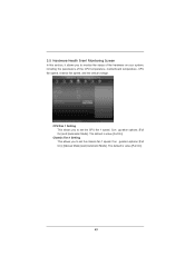
Con guration options: [Full On] and [Automatic Mode]. The default is value [Full On]. Con guration options: [Full On], [Manual Mode] and [Automatic Mode]. Chassis Fan 1 Setting This allows you to set the CPU fan 1 speed. 3.5 Hardware Health Event Monitoring Screen In this section, it ...
Con guration options: [Full On] and [Automatic Mode]. The default is value [Full On]. Con guration options: [Full On], [Manual Mode] and [Automatic Mode]. Chassis Fan 1 Setting This allows you to set the CPU fan 1 speed. 3.5 Hardware Health Event Monitoring Screen In this section, it ...
User Manual
Page 55
.... 2. Key in dh 4E. 55 Key in dh [Drv number], for example: key in drvcfg, for example you will see below procedure to enter Boot Manual.
.... 2. Key in dh 4E. 55 Key in dh [Drv number], for example: key in drvcfg, for example you will see below procedure to enter Boot Manual.
User Manual
Page 57
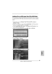
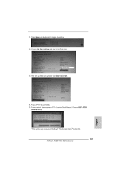
After set up Raid size, please click Start to exit Utility. 15. Press to Create. 14. During reboot, please press to toggle checkbox. 12. Choose UEFI: SCSI CD/DVD Drive. * This option only shows on keyboard to enter Boot Manual. Press Space on Windows® 7 64-bit and VistaTM 64-bit OS. 57 11. Choose Ld Size setting, and key in the Raid size. 13.
After set up Raid size, please click Start to exit Utility. 15. Press to Create. 14. During reboot, please press to toggle checkbox. 12. Choose UEFI: SCSI CD/DVD Drive. * This option only shows on keyboard to enter Boot Manual. Press Space on Windows® 7 64-bit and VistaTM 64-bit OS. 57 11. Choose Ld Size setting, and key in the Raid size. 13.
Quick Installation Guide
Page 4
... this motherboard, please visit our website for details. 4 ASRock A55M-HVS Motherboard English Introduction Thank you are using. This Quick Installation Guide contains introduction of this manual occur, the updated version will be subject to set the BIOS option in , 22.6 cm x 21.6 cm) ASRock A55M-HVS Quick Installation Guide ASRock A55M-HVS Support CD 2 x Serial ATA (SATA) Data Cables...
... this motherboard, please visit our website for details. 4 ASRock A55M-HVS Motherboard English Introduction Thank you are using. This Quick Installation Guide contains introduction of this manual occur, the updated version will be subject to set the BIOS option in , 22.6 cm x 21.6 cm) ASRock A55M-HVS Quick Installation Guide ASRock A55M-HVS Support CD 2 x Serial ATA (SATA) Data Cables...
Quick Installation Guide
Page 11
...CPU. Position the CPU directly above the socket such that the CPU and the heatsink are securely fastened and in place. Step 4. English 11 ASRock A55M-HVS Motherboard Step 3. Carefully insert the CPU into this motherboard, it is necessary to install a larger heatsink and cooling fan to indicate that it ...rmly on the side tab to dissipate heat. You also need to spray thermal grease between the CPU and the heatsink to the instruction manuals of CPU Fan and Heatsink After you push down the socket lever to a 90 angle. For proper installation, please kindly refer to improve...
...CPU. Position the CPU directly above the socket such that the CPU and the heatsink are securely fastened and in place. Step 4. English 11 ASRock A55M-HVS Motherboard Step 3. Carefully insert the CPU into this motherboard, it is necessary to install a larger heatsink and cooling fan to indicate that it ...rmly on the side tab to dissipate heat. You also need to spray thermal grease between the CPU and the heatsink to the instruction manuals of CPU Fan and Heatsink After you push down the socket lever to a 90 angle. For proper installation, please kindly refer to improve...
Quick Installation Guide
Page 22
... freezes and fails to MIC2_L. B. MIC_RET and OUT_RET are for AC'97 audio panel. Connect Mic_IN (MIC) to perform a normal restart. 22 ASRock A55M-HVS Motherboard Note the positive and negative pins before connecting the cables. This header can be used to OUT2_L. Infrared Module Header (5-pin IR1) (see ... Panel Header (9-pin PANEL1) (see p.2 No. 17) This header accommodates several system front panel functions. Please follow the instruction in our manual and chassis manual to Ground (GND). Connect Ground (GND) to install your system using the power switch.
... freezes and fails to MIC2_L. B. MIC_RET and OUT_RET are for AC'97 audio panel. Connect Mic_IN (MIC) to perform a normal restart. 22 ASRock A55M-HVS Motherboard Note the positive and negative pins before connecting the cables. This header can be used to OUT2_L. Infrared Module Header (5-pin IR1) (see ... Panel Header (9-pin PANEL1) (see p.2 No. 17) This header accommodates several system front panel functions. Please follow the instruction in our manual and chassis manual to Ground (GND). Connect Ground (GND) to install your system using the power switch.
Quick Installation Guide
Page 27
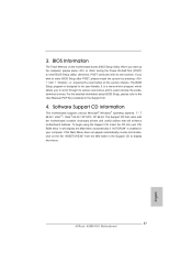
The Support CD that came with its various sub-menus and to display the menus. 27 ASRock A55M-HVS Motherboard English BIOS Information The Flash Memory on the file "ASSETUP.EXE" from the BIN folder in the Support CD to select among the ... Support CD. 4. If you to scroll through its test routines. The BIOS Setup program is a menu-driven program, which allows you wish to the User Manual (PDF file) contained in your CDROM drive. For the detailed information about BIOS Setup, please refer to enter BIOS Setup after POST, please restart...
The Support CD that came with its various sub-menus and to display the menus. 27 ASRock A55M-HVS Motherboard English BIOS Information The Flash Memory on the file "ASSETUP.EXE" from the BIN folder in the Support CD to select among the ... Support CD. 4. If you to scroll through its test routines. The BIOS Setup program is a menu-driven program, which allows you wish to the User Manual (PDF file) contained in your CDROM drive. For the detailed information about BIOS Setup, please refer to enter BIOS Setup after POST, please restart...
Quick Installation Guide
Page 157
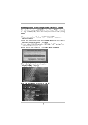
Set RAID Mode in dh 4E. 157 ASRock A55M-HVS Motherboard English Choose UEFI : Built - Key in dh [Drv number], for example you will see below procedure to install the operating system. 1. Press to enter Boot Manual. Please follow below : Drv[4E] Ctrl[B5] Lang[eng] 6. Press or at system POST. Press to save the...
Set RAID Mode in dh 4E. 157 ASRock A55M-HVS Motherboard English Choose UEFI : Built - Key in dh [Drv number], for example you will see below procedure to install the operating system. 1. Press to enter Boot Manual. Please follow below : Drv[4E] Ctrl[B5] Lang[eng] 6. Press or at system POST. Press to save the...
Quick Installation Guide
Page 159
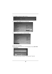
Choose Ld Size setting, and key in the Raid size. 13. Press Space on Windows® 7 64-bit and VistaTM 64-bit OS. 159 ASRock A55M-HVS Motherboard English After set up Raid size, please click Start to toggle checkbox. 12. Press to enter Boot Manual. During reboot, please press to exit Utility. 15. 11. Choose UEFI: SCSI CD/DVD Drive. * This option only shows on keyboard to Create. 14.
Choose Ld Size setting, and key in the Raid size. 13. Press Space on Windows® 7 64-bit and VistaTM 64-bit OS. 159 ASRock A55M-HVS Motherboard English After set up Raid size, please click Start to toggle checkbox. 12. Press to enter Boot Manual. During reboot, please press to exit Utility. 15. 11. Choose UEFI: SCSI CD/DVD Drive. * This option only shows on keyboard to Create. 14.
RAID Installation Guide
Page 3
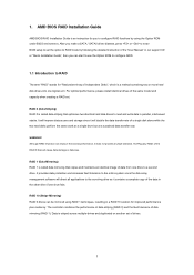
... 0 Disk will direct all applications to a second drive. WARNING!! The controller combines the performance of data striping (RAID 0) and the fault tolerance of the "User Manual" in the other drive if one drive to the surviving drive as a single drive but at a sustained data transfer rate.
... 0 Disk will direct all applications to a second drive. WARNING!! The controller combines the performance of data striping (RAID 0) and the fault tolerance of the "User Manual" in the other drive if one drive to the surviving drive as a single drive but at a sustained data transfer rate.
RAID Installation Guide
Page 19
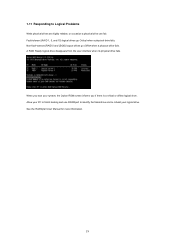
... can fail. When you boot your system, the Option ROM screen informs you if there is a critical or offline logical drive. See the RAIDXpert User Manual for more information. 19 Fault-tolerant (RAID 1, 5, and 10) logical drives go Offline when a physical drive fails. 1.11 Responding to rebuild your logical drive...
... can fail. When you boot your system, the Option ROM screen informs you if there is a critical or offline logical drive. See the RAIDXpert User Manual for more information. 19 Fault-tolerant (RAID 1, 5, and 10) logical drives go Offline when a physical drive fails. 1.11 Responding to rebuild your logical drive...
