
User Manual
Page 7
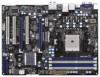
... header - Front panel audio connector - 3 x USB 2.0 headers (support 6 USB 2.0 ports) 7 Supports Energy Ef cient Ethernet 802.3az - CPU/Chassis/Power FAN connector - 24 pin ATX power connector - 8 pin 12V power connector - Supports THX TruStudioTM - Supports Wake-On-LAN - PCIE x1 Gigabit LAN 10/100/1000 Mb/s - Premium Blu-ray audio support - Realtek RTL8111E...
... header - Front panel audio connector - 3 x USB 2.0 headers (support 6 USB 2.0 ports) 7 Supports Energy Ef cient Ethernet 802.3az - CPU/Chassis/Power FAN connector - 24 pin ATX power connector - 8 pin 12V power connector - Supports THX TruStudioTM - Supports Wake-On-LAN - PCIE x1 Gigabit LAN 10/100/1000 Mb/s - Premium Blu-ray audio support - Realtek RTL8111E...
User Manual
Page 12
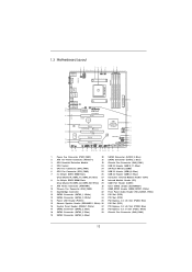
...Taipei AUDIO CODEC Super I/O HD_AUDIO1 1 HDMI_SPDIF1 1 32 31 CHA_FAN2 CHA_FAN3 PCIE1 A55 Pro3 Dual Graphics PCIE2 USB 3.0 CMOS BATTERY PCI1 ErP/EuP Ready XFast USB PCIE3 RoHS PCI2 ... 17 18 19 1 Power Fan Connector (PWR_FAN1) 20 SATA2 Connector (SATA2_2, Blue) 2 ATX 12V Power Connector (ATX12V1) 21 SATA2 Connector (SATA2_1, Blue) 3 CPU Heatsink Retention Module 22 Chassis ... Memory (32Mb) 6 CPU Fan Connector (CPU_FAN2) 25 USB 2.0 Header (USB8_9, Blue) 7 2 x 240-pin DDR3 DIMM Slots 26 USB 2.0 Header (USB6_7, Blue) (Dual Channel A: DDR3_A1, DDR3_B1; Blue) 15 Chassis Speaker...
...Taipei AUDIO CODEC Super I/O HD_AUDIO1 1 HDMI_SPDIF1 1 32 31 CHA_FAN2 CHA_FAN3 PCIE1 A55 Pro3 Dual Graphics PCIE2 USB 3.0 CMOS BATTERY PCI1 ErP/EuP Ready XFast USB PCIE3 RoHS PCI2 ... 17 18 19 1 Power Fan Connector (PWR_FAN1) 20 SATA2 Connector (SATA2_2, Blue) 2 ATX 12V Power Connector (ATX12V1) 21 SATA2 Connector (SATA2_1, Blue) 3 CPU Heatsink Retention Module 22 Chassis ... Memory (32Mb) 6 CPU Fan Connector (CPU_FAN2) 25 USB 2.0 Header (USB8_9, Blue) 7 2 x 240-pin DDR3 DIMM Slots 26 USB 2.0 Header (USB6_7, Blue) (Dual Channel A: DDR3_A1, DDR3_B1; Blue) 15 Chassis Speaker...
User Manual
Page 33
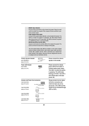
.... The front panel design may differ by chassis. Chassis Speaker Header (4-pin SPEAKER 1) (see p.12 No. 15) Power LED Header (3-pin PLED1) (see p.12 No. 14) 1 PLEDPLED+ PLED+ Chassis and Power Fan Connectors (4-pin CHA_FAN1) (see p.12 No. 22) FAN_SPEED_CONTROL GND +12V CHA_FAN_SPEED (3-pin CHA_FAN2) (see p.12 No. 1) 33 The LED keeps blinking in S1...
.... The front panel design may differ by chassis. Chassis Speaker Header (4-pin SPEAKER 1) (see p.12 No. 15) Power LED Header (3-pin PLED1) (see p.12 No. 14) 1 PLEDPLED+ PLED+ Chassis and Power Fan Connectors (4-pin CHA_FAN1) (see p.12 No. 22) FAN_SPEED_CONTROL GND +12V CHA_FAN_SPEED (3-pin CHA_FAN2) (see p.12 No. 1) 33 The LED keeps blinking in S1...

User Manual
Page 34
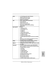
... power supply, please plug your power supply along with Pin 1 and Pin 13. 20-Pin ATX Power Supply Installation 1 13 ATX 12V Power Connector (8-pin ATX12V1) (see p.12 No. 2) 4 8 1 5 Please connect an ATX 12V power supply to the ground pin. CPU Fan Connectors (4-pin CPU_FAN1) (see p.12 No. 5) FAN_SPEED_CONTROL CPU_FAN_SPEED +12V GND 1 2 3 4 Please connect the CPU fan cable to...
... power supply, please plug your power supply along with Pin 1 and Pin 13. 20-Pin ATX Power Supply Installation 1 13 ATX 12V Power Connector (8-pin ATX12V1) (see p.12 No. 2) 4 8 1 5 Please connect an ATX 12V power supply to the ground pin. CPU Fan Connectors (4-pin CPU_FAN1) (see p.12 No. 5) FAN_SPEED_CONTROL CPU_FAN_SPEED +12V GND 1 2 3 4 Please connect the CPU fan cable to...

Quick Installation Guide
Page 2
... 18 19 1 Power Fan Connector (PWR_FAN1) 20 SATA2 Connector (SATA2_2, Blue) 2 ATX 12V Power Connector (ATX12V1) 21 SATA2 Connector (SATA2_1, Blue) 3 CPU Heatsink Retention Module 22 Chassis...Memory (32Mb) 6 CPU Fan Connector (CPU_FAN2) 25 USB 2.0 Header (USB8_9, Blue) 7 2 x 240-pin DDR3 DIMM Slots 26 USB 2.0 Header (USB6_7, Blue) (Dual Channel A: DDR3_A1, DDR3_B1; Blue) 15 Chassis...(SATA2_5, Blue) 39 Chassis Fan Connector (CHA_FAN2) 19 SATA2 Connector (SATA2_4, Blue) 2 ASRock A55 Pro3 Motherboard English White) 29 COM Port Header (COM1) 9 ATX Power Connector (ATXPWR1) 30 ...
... 18 19 1 Power Fan Connector (PWR_FAN1) 20 SATA2 Connector (SATA2_2, Blue) 2 ATX 12V Power Connector (ATX12V1) 21 SATA2 Connector (SATA2_1, Blue) 3 CPU Heatsink Retention Module 22 Chassis...Memory (32Mb) 6 CPU Fan Connector (CPU_FAN2) 25 USB 2.0 Header (USB8_9, Blue) 7 2 x 240-pin DDR3 DIMM Slots 26 USB 2.0 Header (USB6_7, Blue) (Dual Channel A: DDR3_A1, DDR3_B1; Blue) 15 Chassis...(SATA2_5, Blue) 39 Chassis Fan Connector (CHA_FAN2) 19 SATA2 Connector (SATA2_4, Blue) 2 ASRock A55 Pro3 Motherboard English White) 29 COM Port Header (COM1) 9 ATX Power Connector (ATXPWR1) 30 ...
Quick Installation Guide
Page 7
... Content Protection (Realtek ALC892 Audio Codec) - Supports LAN Cable Detection - CPU/Chassis/Power FAN connector - 24 pin ATX power connector - 8 pin 12V power connector - Supports THX TruStudioTM - Front panel audio connector - 3 x USB 2.0 headers (support 6 USB 2.0 ports) English 7 ASRock A55 Pro3 Motherboard PCIE x1 Gigabit LAN 10/100/1000 Mb/s - Realtek RTL8111E - Supports PXE I /O SATA3 USB 3.0 Connector...
... Content Protection (Realtek ALC892 Audio Codec) - Supports LAN Cable Detection - CPU/Chassis/Power FAN connector - 24 pin ATX power connector - 8 pin 12V power connector - Supports THX TruStudioTM - Front panel audio connector - 3 x USB 2.0 headers (support 6 USB 2.0 ports) English 7 ASRock A55 Pro3 Motherboard PCIE x1 Gigabit LAN 10/100/1000 Mb/s - Realtek RTL8111E - Supports PXE I /O SATA3 USB 3.0 Connector...

Quick Installation Guide
Page 30
... etc. Chassis Speaker Header (4-pin SPEAKER 1) (see p.2 No. 15) Power LED Header (3-pin PLED1) (see p.2 No. 14) 1 PLEDPLED+ PLED+ Chassis and Power Fan Connectors (4-pin CHA_FAN1) (see p.2 No. 22) FAN_SPEED_CONTROL GND +12V CHA_FAN_SPEED (3-pin CHA_FAN2) (see p.2 No. 1) 30 ASRock A55 Pro3 Motherboard The front panel design may...LED keeps blinking in S1 sleep state. CHA_FAN1/2/3 fan speed can be controlled through UEFI or AXTU. English (3-pin CHA_FAN3) (see p.2 No. 10) (3-pin PWR_FAN1) (see p.2 No. 39) Please connect the chassis speaker to this header to this header, make...
... etc. Chassis Speaker Header (4-pin SPEAKER 1) (see p.2 No. 15) Power LED Header (3-pin PLED1) (see p.2 No. 14) 1 PLEDPLED+ PLED+ Chassis and Power Fan Connectors (4-pin CHA_FAN1) (see p.2 No. 22) FAN_SPEED_CONTROL GND +12V CHA_FAN_SPEED (3-pin CHA_FAN2) (see p.2 No. 1) 30 ASRock A55 Pro3 Motherboard The front panel design may...LED keeps blinking in S1 sleep state. CHA_FAN1/2/3 fan speed can be controlled through UEFI or AXTU. English (3-pin CHA_FAN3) (see p.2 No. 10) (3-pin PWR_FAN1) (see p.2 No. 39) Please connect the chassis speaker to this header to this header, make...

Quick Installation Guide
Page 31
..., please plug your power supply along with Pin 1 and Pin 13. 20-Pin ATX Power Supply Installation 1 13 ATX 12V Power Connector (8-pin ATX12V1) (see p.2 No. 2) 4 8 1 5 Please connect an ATX 12V power supply to the ground pin. English 31 ASRock A55 Pro3 Motherboard Though this motherboard provides 4-Pin CPU fan (Quiet Fan) support, the 3-Pin CPU fan still can still work successfully...
..., please plug your power supply along with Pin 1 and Pin 13. 20-Pin ATX Power Supply Installation 1 13 ATX 12V Power Connector (8-pin ATX12V1) (see p.2 No. 2) 4 8 1 5 Please connect an ATX 12V power supply to the ground pin. English 31 ASRock A55 Pro3 Motherboard Though this motherboard provides 4-Pin CPU fan (Quiet Fan) support, the 3-Pin CPU fan still can still work successfully...

Quick Installation Guide
Page 134
... (4 핀 CPU_FAN1) (2 5 FAN_SPEED_CONTROL CPU_FAN_SPEED +12V GND 1 2 3 4 CPU 4 핀 CPU 3 핀 CPU CPU 3 핀 CPU 1-3 1-3 3 (3 핀 CPU_FAN2) (2 6 GND +12V CPU_FAN_SPEED ATX (24 핀 ATXPWR1) (2 9 12 24 ATX 1 13 24 핀 ATX 12 24 종래의 20 핀 ATX 20 핀 ATX Pin 1 과 Pin 13 20 핀 ATX 1 13 한 국 어 134 ASRock A55 Pro3 Motherboard
... (4 핀 CPU_FAN1) (2 5 FAN_SPEED_CONTROL CPU_FAN_SPEED +12V GND 1 2 3 4 CPU 4 핀 CPU 3 핀 CPU CPU 3 핀 CPU 1-3 1-3 3 (3 핀 CPU_FAN2) (2 6 GND +12V CPU_FAN_SPEED ATX (24 핀 ATXPWR1) (2 9 12 24 ATX 1 13 24 핀 ATX 12 24 종래의 20 핀 ATX 20 핀 ATX Pin 1 과 Pin 13 20 핀 ATX 1 13 한 국 어 134 ASRock A55 Pro3 Motherboard

Quick Installation Guide
Page 150
ATX 12V 8 ピン ATX12V1 2 を参照 4 8 1 5 CPU に Vcore ATX 12V 8-pin ATX 12V 4-pin ATX 12V 4-pin ATX Pin 1 と Pin 5 4 8 9 ピン COM1 29 を参照 4-Pin ATX 12V 1 5 この COM1 日本語 150 ASRock A55 Pro3 Motherboard
ATX 12V 8 ピン ATX12V1 2 を参照 4 8 1 5 CPU に Vcore ATX 12V 8-pin ATX 12V 4-pin ATX 12V 4-pin ATX Pin 1 と Pin 5 4 8 9 ピン COM1 29 を参照 4-Pin ATX 12V 1 5 この COM1 日本語 150 ASRock A55 Pro3 Motherboard

Quick Installation Guide
Page 163
...;的 20-pin ATX 20-pin ATX Pin 1 和 Pin 13 20-Pin ATX 1 13 ATX 12V 接頭 (8 針 ATX12V1) ( 見第 2 頁第 2 項 ) 4 8 1 5 ATX 12V 8-pin ATX 12V 4-pin ATX 12V 4-pin ATX 12V Pin 1 和 Pin 5 插上電 源接頭。 4 8 4-Pin ATX 12V 1 5 (9 針 COM1) ( 見第 2 頁第 29 項 ) 這個 COM1 簡體中文 163 ASRock A55 Pro3 Motherboard
...;的 20-pin ATX 20-pin ATX Pin 1 和 Pin 13 20-Pin ATX 1 13 ATX 12V 接頭 (8 針 ATX12V1) ( 見第 2 頁第 2 項 ) 4 8 1 5 ATX 12V 8-pin ATX 12V 4-pin ATX 12V 4-pin ATX 12V Pin 1 和 Pin 5 插上電 源接頭。 4 8 4-Pin ATX 12V 1 5 (9 針 COM1) ( 見第 2 頁第 29 項 ) 這個 COM1 簡體中文 163 ASRock A55 Pro3 Motherboard

Quick Installation Guide
Page 177
... (24 針 ATXPWR1) ( 見第 2 頁第 9 項 ) 12 24 請將 ATX 1 13 24-pin ATX 12 24 20-pin ATX 20-pin ATX 著 Pin 1 和 Pin 13 20-Pin ATX 1 13 ATX 12V (8 針 ATX12V1) ( 見第 2 頁第 2 項 ) 4 8 1 5 ATX 12V 8-pin ATX 12V 4-pin ATX 12V 4-pin ATX 12V 4 8 順著 Pin 1 和 Pin 5 4-Pin ATX 12V 1 5 繁體中文 177 ASRock A55 Pro3 Motherboard
... (24 針 ATXPWR1) ( 見第 2 頁第 9 項 ) 12 24 請將 ATX 1 13 24-pin ATX 12 24 20-pin ATX 20-pin ATX 著 Pin 1 和 Pin 13 20-Pin ATX 1 13 ATX 12V (8 針 ATX12V1) ( 見第 2 頁第 2 項 ) 4 8 1 5 ATX 12V 8-pin ATX 12V 4-pin ATX 12V 4-pin ATX 12V 4 8 順著 Pin 1 和 Pin 5 4-Pin ATX 12V 1 5 繁體中文 177 ASRock A55 Pro3 Motherboard


