
User Manual
Page 4
...Specifications 2 1.3 Motherboard Layout 6 1.4 I/O Panel 8 Chapter 2 Installation 9 2.1 Installing the CPU 10 2.2 Installing the CPU Fan and Heatsink 12 2.3 Installing Memory Modules (DIMM) 20 2.4 Expansion Slots (PCI and PCI Express Slots) 22 2.5 Jumpers Setup 23 2.6 Onboard Headers and Connectors 24 2.7 M.2_SSD (NGFF) Module Installation Guide (M2_1) 28 Chapter 3 Software and Utilities Operation 31 3.1 Installing Drivers 31 3.2 ASRock Motherboard Utility (A-Tuning) 32 3.2.1 Installing ASRock Motherboard Utility (A-Tuning) 32 3.2.2 Using ASRock Motherboard Utility...
...Specifications 2 1.3 Motherboard Layout 6 1.4 I/O Panel 8 Chapter 2 Installation 9 2.1 Installing the CPU 10 2.2 Installing the CPU Fan and Heatsink 12 2.3 Installing Memory Modules (DIMM) 20 2.4 Expansion Slots (PCI and PCI Express Slots) 22 2.5 Jumpers Setup 23 2.6 Onboard Headers and Connectors 24 2.7 M.2_SSD (NGFF) Module Installation Guide (M2_1) 28 Chapter 3 Software and Utilities Operation 31 3.1 Installing Drivers 31 3.2 ASRock Motherboard Utility (A-Tuning) 32 3.2.1 Installing ASRock Motherboard Utility (A-Tuning) 32 3.2.2 Using ASRock Motherboard Utility...
User Manual
Page 6
... software and utilities. A520M-HDVP/DASH Chapter 1 Introduction Thank you for specific information about the model you require technical support related to this documentation occur, the updated version will be subject to quality and endurance. In case any modifications of the motherboard and step-by-step installation guides. If you are using. Chapter 3 contains the operation guide of the BIOS setup. You may find the latest VGA cards and CPU support list on ASRock...
... software and utilities. A520M-HDVP/DASH Chapter 1 Introduction Thank you for specific information about the model you require technical support related to this documentation occur, the updated version will be subject to quality and endurance. In case any modifications of the motherboard and step-by-step installation guides. If you are using. Chapter 3 contains the operation guide of the BIOS setup. You may find the latest VGA cards and CPU support list on ASRock...

User Manual
Page 9
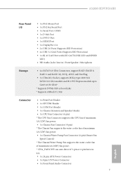
... LED (ACT/LINK LED and SPEED LED) • HD Audio Jacks: Line in / Front Speaker / Microphone Storage • 4 x SATA3 6.0 Gb/s Connectors, support RAID (RAID 0, RAID 1 and RAID 10), NCQ, AHCI and Hot Plug • 1 x Ultra M.2 Socket, supports M Key type 2280 M.2 SATA3 6.0 Gb/s module and M.2 PCI Express module up to Gen3 x4 (32 Gb/s)* * Supports NVMe SSD as boot disks * Supports ASRock U.2 Kit Connector • 1 x Print Port Header • 1 x SPI TPM Header • 1 x COM Port Header • 1 x Chassis Intrusion and Speaker Header • 1 x CPU Fan Connector (4-pin) * The CPU Fan...
... LED (ACT/LINK LED and SPEED LED) • HD Audio Jacks: Line in / Front Speaker / Microphone Storage • 4 x SATA3 6.0 Gb/s Connectors, support RAID (RAID 0, RAID 1 and RAID 10), NCQ, AHCI and Hot Plug • 1 x Ultra M.2 Socket, supports M Key type 2280 M.2 SATA3 6.0 Gb/s module and M.2 PCI Express module up to Gen3 x4 (32 Gb/s)* * Supports NVMe SSD as boot disks * Supports ASRock U.2 Kit Connector • 1 x Print Port Header • 1 x SPI TPM Header • 1 x COM Port Header • 1 x Chassis Intrusion and Speaker Header • 1 x CPU Fan Connector (4-pin) * The CPU Fan...
User Manual
Page 10
...- English 5 A520M-HDVP/DASH BIOS Feature Hardware Monitor OS Certifications • 2 x USB 2.0 Headers (Support 4 USB 2.0 ports) (Supports ESD Protection) • 1 x USB 3.2 Gen1 Header (Supports 2 USB 3.2 Gen1 ports) (Supports ESD Protection) • AMI UEFI Legal BIOS with overclocking, including adjusting the setting in the BIOS, applying Untied Overclocking Technology, or using third-party overclocking tools. ture): CPU, Chassis, Chassis/Water Pump Fans • Fan Multi-Speed Control: CPU, Chassis, Chassis/Water Pump Fans • CASE OPEN detection • Voltage monitoring: +12V...
...- English 5 A520M-HDVP/DASH BIOS Feature Hardware Monitor OS Certifications • 2 x USB 2.0 Headers (Support 4 USB 2.0 ports) (Supports ESD Protection) • 1 x USB 3.2 Gen1 Header (Supports 2 USB 3.2 Gen1 ports) (Supports ESD Protection) • AMI UEFI Legal BIOS with overclocking, including adjusting the setting in the BIOS, applying Untied Overclocking Technology, or using third-party overclocking tools. ture): CPU, Chassis, Chassis/Water Pump Fans • Fan Multi-Speed Control: CPU, Chassis, Chassis/Water Pump Fans • CASE OPEN detection • Voltage monitoring: +12V...

User Manual
Page 12
...1 8 pin 12V Power Connector (ATX12V1) 2 CPU Fan Connector (CPU_FAN1) 3 2 x 288-pin DDR4 DIMM Slots (DDR4_A1, DDR4_B1) 4 ATX Power Connector (ATXPWR1) 5 USB 3.2 Gen1 Header (USB3_5_6) 6 SPI TPM Header (SPI_TPM_J1) 7 SATA3 Connector (SATA3_3) (Upper), SATA3 Connector (SATA3_4) (Lower) 8 SATA3 Connector (SATA3_1) (Upper), SATA3 Connector (SATA3_2) (Lower) 9 System Panel Header (PANEL1) 10 Clear CMOS Jumper (CLRCMOS1) 11 Chassis Intrusion and Speaker Header (SPK_CI1) 12 Chassis/Water Pump Fan Connector (CHA_FAN1/WP) 13 USB 2.0 Header (USB_3_4) 14 USB 2.0 Header (USB_5_6) 15 Print Port Header (LPT1...
...1 8 pin 12V Power Connector (ATX12V1) 2 CPU Fan Connector (CPU_FAN1) 3 2 x 288-pin DDR4 DIMM Slots (DDR4_A1, DDR4_B1) 4 ATX Power Connector (ATXPWR1) 5 USB 3.2 Gen1 Header (USB3_5_6) 6 SPI TPM Header (SPI_TPM_J1) 7 SATA3 Connector (SATA3_3) (Upper), SATA3 Connector (SATA3_4) (Lower) 8 SATA3 Connector (SATA3_1) (Upper), SATA3 Connector (SATA3_2) (Lower) 9 System Panel Header (PANEL1) 10 Clear CMOS Jumper (CLRCMOS1) 11 Chassis Intrusion and Speaker Header (SPK_CI1) 12 Chassis/Water Pump Fan Connector (CHA_FAN1/WP) 13 USB 2.0 Header (USB_3_4) 14 USB 2.0 Header (USB_5_6) 15 Print Port Header (LPT1...

User Manual
Page 27
..., please connect a chassis fan to install expansion cards that the power supply is switched off or the power cord is unplugged. PCIe slots: PCIE1 (PCIe 3.0 x1 slot) is used for PCI Express x1 lane width cards. 2.4 Expansion Slots (PCI and PCI Express Slots) There are 1 PCI slot and 3 PCI Express slots on the motherboard. PCI slot: The PCI1 slot is used to the motherboard's chassis fan connector (CHA_FAN1/WP or CHA_FAN2) when using multiple graphics cards. 22 English PCIE2 (PCIe 3.0 x16 slot) is used for the card before you start the installation. Before installing an...
..., please connect a chassis fan to install expansion cards that the power supply is switched off or the power cord is unplugged. PCIe slots: PCIE1 (PCIe 3.0 x1 slot) is used for PCI Express x1 lane width cards. 2.4 Expansion Slots (PCI and PCI Express Slots) There are 1 PCI slot and 3 PCI Express slots on the motherboard. PCI slot: The PCI1 slot is used to the motherboard's chassis fan connector (CHA_FAN1/WP or CHA_FAN2) when using multiple graphics cards. 22 English PCIE2 (PCIe 3.0 x16 slot) is used for the card before you start the installation. Before installing an...

User Manual
Page 28
... default setup, please turn off the computer and unplug the power cord, then use a jumper cap to clear the record of previous chassis intrusion status. Clear CMOS Jumper (CLRCMOS1) (see p.6, No. 10) 2-pin Jumper Short: Clear CMOS Open: Default CLRCMOS1 allows you clear the CMOS, the case open may be detected. If you need to remove the jumper cap after clearing the CMOS. English 23 Please remember to clear the CMOS when you just finish updating the BIOS...
... default setup, please turn off the computer and unplug the power cord, then use a jumper cap to clear the record of previous chassis intrusion status. Clear CMOS Jumper (CLRCMOS1) (see p.6, No. 10) 2-pin Jumper Short: Clear CMOS Open: Default CLRCMOS1 allows you clear the CMOS, the case open may be detected. If you need to remove the jumper cap after clearing the CMOS. English 23 Please remember to clear the CMOS when you just finish updating the BIOS...
User Manual
Page 30
... HD audio panel only. Connect Mic_IN (MIC) to Ground (GND). This USB 3.2 Gen1 header can support two ports. C. E. D. Each USB 2.0 header can support two ports. Connect Ground (GND) to MIC2_L. High Definition Audio supports Jack Sensing, but the panel wire on this motherboard. USB_PWR PP+ GND DUMMY 1 GND P+ PUSB_PWR There are for connecting audio devices to OUT2_L. Please follow the instructions in the Realtek Control panel and adjust "Recording Volume". 25 English A520M-HDVP/DASH Serial ATA3 Connectors (SATA3_1...
... HD audio panel only. Connect Mic_IN (MIC) to Ground (GND). This USB 3.2 Gen1 header can support two ports. C. E. D. Each USB 2.0 header can support two ports. Connect Ground (GND) to MIC2_L. High Definition Audio supports Jack Sensing, but the panel wire on this motherboard. USB_PWR PP+ GND DUMMY 1 GND P+ PUSB_PWR There are for connecting audio devices to OUT2_L. Please follow the instructions in the Realtek Control panel and adjust "Recording Volume". 25 English A520M-HDVP/DASH Serial ATA3 Connectors (SATA3_1...

User Manual
Page 31
... 1 2 3 4 This motherboard provides one 4-Pin water cooling chassis fan connector. To use a 4-pin ATX power supply, please plug it along Pin 1 and Pin 5. *Warning: Please make sure that the power cable connected is for the CPU and not the graphics card. Chassis Fan Connector (4-pin CHA_FAN2) (see p.6, No. 17) FAN_SPEED_CONTROL CHA_FAN_SPEED +12V GND 4 Please connect fan cables 3 to the fan connector and 2 1 match the black wire to this connector. To 4 1 use a 20-pin ATX power supply, please plug it along Pin 1 and Pin 13. Do not plug the PCIe power cable to...
... 1 2 3 4 This motherboard provides one 4-Pin water cooling chassis fan connector. To use a 4-pin ATX power supply, please plug it along Pin 1 and Pin 5. *Warning: Please make sure that the power cable connected is for the CPU and not the graphics card. Chassis Fan Connector (4-pin CHA_FAN2) (see p.6, No. 17) FAN_SPEED_CONTROL CHA_FAN_SPEED +12V GND 4 Please connect fan cables 3 to the fan connector and 2 1 match the black wire to this connector. To 4 1 use a 20-pin ATX power supply, please plug it along Pin 1 and Pin 13. Do not plug the PCIe power cable to...
User Manual
Page 36
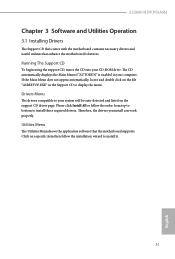
... automatically displays the Main Menu if "AUTORUN" is enabled in your system will be auto-detected and listed on the file "ASRSETUP.EXE" in the Support CD to install it. 31 English Utilities Menu The Utilities Menu shows the application software that enhance the motherboard's features. Therefore, the drivers you install can work properly. Please click Install All or follow the installation wizard to display the menu. A520M-HDVP/DASH Chapter 3 Software and Utilities Operation 3.1 Installing Drivers The Support CD...
... automatically displays the Main Menu if "AUTORUN" is enabled in your system will be auto-detected and listed on the file "ASRSETUP.EXE" in the Support CD to install it. 31 English Utilities Menu The Utilities Menu shows the application software that enhance the motherboard's features. Therefore, the drivers you install can work properly. Please click Install All or follow the installation wizard to display the menu. A520M-HDVP/DASH Chapter 3 Software and Utilities Operation 3.1 Installing Drivers The Support CD...
User Manual
Page 49
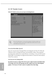
... be undetectable. 4.3 OC Tweaker Screen In the OC Tweaker screen, you see on processors with integrated graphics. Overclock Mode(Bus Speed) Select the overclock mode. VDD_SOC also determines the GPU voltage on your HDD's may be enabled to force this voltage. 44 English "SoC/Uncore OC Mode" needs to support memory and Infinity Fabric overclocking. When overclocking also the PCIe, PCI, SATA and USB busses will be overcloked which may cause instability or failure.
... be undetectable. 4.3 OC Tweaker Screen In the OC Tweaker screen, you see on processors with integrated graphics. Overclock Mode(Bus Speed) Select the overclock mode. VDD_SOC also determines the GPU voltage on your HDD's may be enabled to force this voltage. 44 English "SoC/Uncore OC Mode" needs to support memory and Infinity Fabric overclocking. When overclocking also the PCIe, PCI, SATA and USB busses will be overcloked which may cause instability or failure.

User Manual
Page 54
... a sound card is installed. Front Panel Enable/disable front panel HD audio. Restore on AC/Power Loss Select the power state after a power failure. If [Power Off] is selected, the system will remain off when the power recovers. Onboard LAN Enable or disable the onboard network interface controller. 49 English Set to Auto to set the size of the UMA frame buffer. If [Power On] is selected, the power will start to boot up when the power recovers. 4.4.2 Onboard Devices Configuration A520M-HDVP/DASH SR-IOV Support Enable/disable...
... a sound card is installed. Front Panel Enable/disable front panel HD audio. Restore on AC/Power Loss Select the power state after a power failure. If [Power Off] is selected, the system will remain off when the power recovers. Onboard LAN Enable or disable the onboard network interface controller. 49 English Set to Auto to set the size of the UMA frame buffer. If [Power On] is selected, the power will start to boot up when the power recovers. 4.4.2 Onboard Devices Configuration A520M-HDVP/DASH SR-IOV Support Enable/disable...

User Manual
Page 56
.../2 Keyboard S4/S5 Wakeup Support Allow the system to be waked up by a PCI or PCIE device and enable wake on LAN. We recommend disabling Deep Sleep for ACPI S3 power saving. RTC Alarm Power On Allow the system to be waked up by the real time clock alarm. Set it to By OS to let it be waked up by your operating system. 51 English 4.4.4 ACPI Configuration A520M-HDVP/DASH Suspend to RAM...
.../2 Keyboard S4/S5 Wakeup Support Allow the system to be waked up by a PCI or PCIE device and enable wake on LAN. We recommend disabling Deep Sleep for ACPI S3 power saving. RTC Alarm Power On Allow the system to be waked up by the real time clock alarm. Set it to By OS to let it be waked up by your operating system. 51 English 4.4.4 ACPI Configuration A520M-HDVP/DASH Suspend to RAM...

Quick Installation Guide
Page 4
...1 8 pin 12V Power Connector (ATX12V1) 2 CPU Fan Connector (CPU_FAN1) 3 2 x 288-pin DDR4 DIMM Slots (DDR4_A1, DDR4_B1) 4 ATX Power Connector (ATXPWR1) 5 USB 3.2 Gen1 Header (USB3_5_6) 6 SPI TPM Header (SPI_TPM_J1) 7 SATA3 Connector (SATA3_3) (Upper), SATA3 Connector (SATA3_4) (Lower) 8 SATA3 Connector (SATA3_1) (Upper), SATA3 Connector (SATA3_2) (Lower) 9 System Panel Header (PANEL1) 10 Clear CMOS Jumper (CLRCMOS1) 11 Chassis Intrusion and Speaker Header (SPK_CI1) 12 Chassis/Water Pump Fan Connector (CHA_FAN1/WP) 13 USB 2.0 Header (USB_3_4) 14 USB 2.0 Header (USB_5_6) 15 Print Port Header (LPT1...
...1 8 pin 12V Power Connector (ATX12V1) 2 CPU Fan Connector (CPU_FAN1) 3 2 x 288-pin DDR4 DIMM Slots (DDR4_A1, DDR4_B1) 4 ATX Power Connector (ATXPWR1) 5 USB 3.2 Gen1 Header (USB3_5_6) 6 SPI TPM Header (SPI_TPM_J1) 7 SATA3 Connector (SATA3_3) (Upper), SATA3 Connector (SATA3_4) (Lower) 8 SATA3 Connector (SATA3_1) (Upper), SATA3 Connector (SATA3_2) (Lower) 9 System Panel Header (PANEL1) 10 Clear CMOS Jumper (CLRCMOS1) 11 Chassis Intrusion and Speaker Header (SPK_CI1) 12 Chassis/Water Pump Fan Connector (CHA_FAN1/WP) 13 USB 2.0 Header (USB_3_4) 14 USB 2.0 Header (USB_5_6) 15 Print Port Header (LPT1...
Quick Installation Guide
Page 6
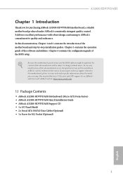
... to change without further notice. Because the motherboard specifications and the BIOS software might be updated, the content of this documentation occur, the updated version will be available on ASRock's website as well. ASRock website http://www.asrock.com. 1.1 Package Contents • ASRock A520M-HDVP/DASH Motherboard (Micro ATX Form Factor) • ASRock A520M-HDVP/DASH Quick Installation Guide • ASRock A520M-HDVP/DASH Support CD • 1 x I/O Panel Shield • 2 x Serial ATA (SATA) Data Cables (Optional) • 1 x Screw for specific information about the model you...
... to change without further notice. Because the motherboard specifications and the BIOS software might be updated, the content of this documentation occur, the updated version will be available on ASRock's website as well. ASRock website http://www.asrock.com. 1.1 Package Contents • ASRock A520M-HDVP/DASH Motherboard (Micro ATX Form Factor) • ASRock A520M-HDVP/DASH Quick Installation Guide • ASRock A520M-HDVP/DASH Support CD • 1 x I/O Panel Shield • 2 x Serial ATA (SATA) Data Cables (Optional) • 1 x Screw for specific information about the model you...
Quick Installation Guide
Page 7
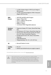
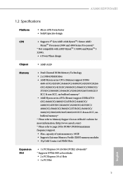
A520M-HDVP/DASH 1.2 Specifications Platform CPU • Micro ATX Form Factor • Solid Capacitor design • Supports 3rd Gen AMD AM4 RyzenTM / future AMD RyzenTM Processors (3000 and 4000 Series Processors)* * Not compatible with AMD RyzenTM 5 3400G and RyzenTM 3 3200G. • 6 Power Phase design Chipset • AMD A520 Memory • Dual Channel DDR4 Memory Technology • 2 x DDR4 DIMM Slots • AMD Ryzen series CPUs (Matisse) support DDR4 4600+(OC)/4533(OC)/4466(OC)/4400(OC)/4333(OC...
A520M-HDVP/DASH 1.2 Specifications Platform CPU • Micro ATX Form Factor • Solid Capacitor design • Supports 3rd Gen AMD AM4 RyzenTM / future AMD RyzenTM Processors (3000 and 4000 Series Processors)* * Not compatible with AMD RyzenTM 5 3400G and RyzenTM 3 3200G. • 6 Power Phase design Chipset • AMD A520 Memory • Dual Channel DDR4 Memory Technology • 2 x DDR4 DIMM Slots • AMD Ryzen series CPUs (Matisse) support DDR4 4600+(OC)/4533(OC)/4466(OC)/4400(OC)/4333(OC...
Quick Installation Guide
Page 9
... LED (ACT/LINK LED and SPEED LED) • HD Audio Jacks: Line in / Front Speaker / Microphone Storage • 4 x SATA3 6.0 Gb/s Connectors, support RAID (RAID 0, RAID 1 and RAID 10), NCQ, AHCI and Hot Plug • 1 x Ultra M.2 Socket, supports M Key type 2280 M.2 SATA3 6.0 Gb/s module and M.2 PCI Express module up to Gen3 x4 (32 Gb/s)* * Supports NVMe SSD as boot disks * Supports ASRock U.2 Kit Connector • 1 x Print Port Header • 1 x SPI TPM Header • 1 x COM Port Header • 1 x Chassis Intrusion and Speaker Header • 1 x CPU Fan Connector (4-pin) * The CPU Fan...
... LED (ACT/LINK LED and SPEED LED) • HD Audio Jacks: Line in / Front Speaker / Microphone Storage • 4 x SATA3 6.0 Gb/s Connectors, support RAID (RAID 0, RAID 1 and RAID 10), NCQ, AHCI and Hot Plug • 1 x Ultra M.2 Socket, supports M Key type 2280 M.2 SATA3 6.0 Gb/s module and M.2 PCI Express module up to Gen3 x4 (32 Gb/s)* * Supports NVMe SSD as boot disks * Supports ASRock U.2 Kit Connector • 1 x Print Port Header • 1 x SPI TPM Header • 1 x COM Port Header • 1 x Chassis Intrusion and Speaker Header • 1 x CPU Fan Connector (4-pin) * The CPU Fan...

Quick Installation Guide
Page 24
... connect a chassis fan to install expansion cards that the power supply is switched off or the power cord is used for PCI Express x16 lane width graphics cards. PCI slot: The PCI1 slot is used to the motherboard's chassis fan connector (CHA_FAN1/WP or CHA_FAN2) when using multiple graphics cards. 22 English PCIE3 (PCIe 3.0 x1 slot) is unplugged. Please read the documentation of the expansion card and make sure that have 32-bit PCI interface. 2.4 Expansion Slots (PCI and PCI Express Slots) There are 1 PCI slot and 3 PCI Express slots...
... connect a chassis fan to install expansion cards that the power supply is switched off or the power cord is used for PCI Express x16 lane width graphics cards. PCI slot: The PCI1 slot is used to the motherboard's chassis fan connector (CHA_FAN1/WP or CHA_FAN2) when using multiple graphics cards. 22 English PCIE3 (PCIe 3.0 x1 slot) is unplugged. Please read the documentation of the expansion card and make sure that have 32-bit PCI interface. 2.4 Expansion Slots (PCI and PCI Express Slots) There are 1 PCI slot and 3 PCI Express slots...

Quick Installation Guide
Page 28
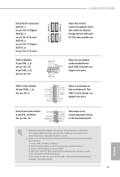
... CPU and not the graphics card. English ATX Power Connector (24-pin ATXPWR1) (see p.1, No. 17) FAN_SPEED_CONTROL CHA_FAN_SPEED +12V GND 4 Please connect fan cables 3 to the fan connector and 2 1 match the black wire to connect a 3-Pin chassis water cooler fan, please connect it along Pin 1 and Pin 13. To use a 4-pin ATX power supply, please plug it to Pin 1-3. CPU_FAN_SPEED GND FAN_SPEED_CONTROL vides a 4-Pin CPU fan 1 2 3 4 (Quiet Fan) connector. ATX 12V Power Connector (8-pin ATX12V1) (see p.1, No. 2) +12V This motherboard pro- CPU Fan Connector (4-pin...
... CPU and not the graphics card. English ATX Power Connector (24-pin ATXPWR1) (see p.1, No. 17) FAN_SPEED_CONTROL CHA_FAN_SPEED +12V GND 4 Please connect fan cables 3 to the fan connector and 2 1 match the black wire to connect a 3-Pin chassis water cooler fan, please connect it along Pin 1 and Pin 13. To use a 4-pin ATX power supply, please plug it to Pin 1-3. CPU_FAN_SPEED GND FAN_SPEED_CONTROL vides a 4-Pin CPU fan 1 2 3 4 (Quiet Fan) connector. ATX 12V Power Connector (8-pin ATX12V1) (see p.1, No. 2) +12V This motherboard pro- CPU Fan Connector (4-pin...

RAID Installation Guide
Page 9
... please open the boot menu that is the first. A. B. Three drivers must be loaded. It might look different when using a different version driver package. 9 During Windows installation process, when Disk selection page show up, please click . Using SATA/NVMe RAID driver package (version 9.2.0.127) from . It should list the USB drive as a UEFI device. This is shown in this to find the driver inside your USB flash drive. Click to boot from AMD website. Then restart...
... please open the boot menu that is the first. A. B. Three drivers must be loaded. It might look different when using a different version driver package. 9 During Windows installation process, when Disk selection page show up, please click . Using SATA/NVMe RAID driver package (version 9.2.0.127) from . It should list the USB drive as a UEFI device. This is shown in this to find the driver inside your USB flash drive. Click to boot from AMD website. Then restart...


