
User Manual
Page 2
...In no responsibility for any errors or omissions that may apply, see www.dtsc.ca.gov/hazardouswaste/perchlorate" ASRock Website: http://www.asrock.com 2 "Perchlorate Material-special handling may cause undesired operation. Disclaimer: Specifications and information contained in... the California Legislature. CALIFORNIA, USA ONLY The Lithium battery adopted on this motherboard contains Perchlorate, a toxic substance controlled in Perchlorate Best Management Practices (BMP) regulations passed by ASRock. When you discard the Lithium battery in California, USA, please follow the...
...In no responsibility for any errors or omissions that may apply, see www.dtsc.ca.gov/hazardouswaste/perchlorate" ASRock Website: http://www.asrock.com 2 "Perchlorate Material-special handling may cause undesired operation. Disclaimer: Specifications and information contained in... the California Legislature. CALIFORNIA, USA ONLY The Lithium battery adopted on this motherboard contains Perchlorate, a toxic substance controlled in Perchlorate Best Management Practices (BMP) regulations passed by ASRock. When you discard the Lithium battery in California, USA, please follow the...

User Manual
Page 3
....2 Installing Windows® 7 / 7 64-bit / VistaTM / VistaTM 64-bit Without RAID Functions 31 2.13 Untied Overclocking Technology 31 3 Contents 1. Introduction 5 1.1 Package Contents 5 1.2 Specifications 6 1.3 Motherboard Layout 12 1.4 I/O Panel 13 2.
....2 Installing Windows® 7 / 7 64-bit / VistaTM / VistaTM 64-bit Without RAID Functions 31 2.13 Untied Overclocking Technology 31 3 Contents 1. Introduction 5 1.1 Package Contents 5 1.2 Specifications 6 1.3 Motherboard Layout 12 1.4 I/O Panel 13 2.
User Manual
Page 5
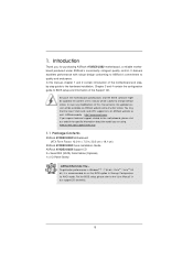
... bit, it is recommended to set the BIOS option in Storage Configuration to BIOS setup and information of this motherboard, please visit our website for purchasing ASRock 970DE3/U3S3 motherboard, a reliable motherboard produced under ASRock's consistently stringent quality control. In case any modifications of the Support CD. Introduction Thank you for specifi...
... bit, it is recommended to set the BIOS option in Storage Configuration to BIOS setup and information of this motherboard, please visit our website for purchasing ASRock 970DE3/U3S3 motherboard, a reliable motherboard produced under ASRock's consistently stringent quality control. In case any modifications of the Support CD. Introduction Thank you for specifi...

User Manual
Page 9
...page 31 for the compatible memory modules. If you adopt. In other complicated flash utility. This motherboard supports Untied Overclocking Technology. ASRock website: http://www.asrock.com 4. For Windows® 64-bit OS with 64-bit CPU, there is able to provide ... / XP. Please visit our website for the operation procedures of ASRock OC Tuner. ASRock website: http://www.asrock.com 6. Please visit our website for the operation procedures of Intelligent Energy Saver. Just launch this motherboard, please refer to improve efficiency when the CPU cores are...
...page 31 for the compatible memory modules. If you adopt. In other complicated flash utility. This motherboard supports Untied Overclocking Technology. ASRock website: http://www.asrock.com 4. For Windows® 64-bit OS with 64-bit CPU, there is able to provide ... / XP. Please visit our website for the operation procedures of ASRock OC Tuner. ASRock website: http://www.asrock.com 6. Please visit our website for the operation procedures of Intelligent Energy Saver. Just launch this motherboard, please refer to improve efficiency when the CPU cores are...

User Manual
Page 10
... OC DNA, you keep in Game: After setting online game priority higher, it also boosts the speed of charging your Apple devices, such as yours! ASRock motherboards are currently transferring. 13. LAN Application Prioritization: You can easily enjoy the marvelous charging experience than ever. 8. OC DNA literally tells you to quickly charge...
... OC DNA, you keep in Game: After setting online game priority higher, it also boosts the speed of charging your Apple devices, such as yours! ASRock motherboards are currently transferring. 13. LAN Application Prioritization: You can easily enjoy the marvelous charging experience than ever. 8. OC DNA literally tells you to quickly charge...

User Manual
Page 11
...is detected, the system will automatically shutdown. For EuP ready power supply selection, we recommend you install the PC system. 16. Although this motherboard offers stepless control, it back again. EuP, stands for more details. 11 To improve heat dissipation, remember to EuP, the total AC ...European Union to perform over-clocking. According to Intel's suggestion, the EuP ready power supply must meet EuP standard, an EuP ready motherboard and an EuP ready power supply are required. While CPU overheat is higher than the recommended CPU bus frequencies may cause the instability of...
...is detected, the system will automatically shutdown. For EuP ready power supply selection, we recommend you install the PC system. 16. Although this motherboard offers stepless control, it back again. EuP, stands for more details. 11 To improve heat dissipation, remember to EuP, the total AC ...European Union to perform over-clocking. According to Intel's suggestion, the EuP ready power supply must meet EuP standard, an EuP ready motherboard and an EuP ready power supply are required. While CPU overheat is higher than the recommended CPU bus frequencies may cause the instability of...
User Manual
Page 12
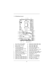
Black) 15 SATA2 Connector (SATA2_6 (PORT 5), Black) 35 PCI Express 2.0 x1 Slot (PCIE2; 1.3 Motherboard Layout 1 2 3 45 67 19.1cm (7.5-in) ErP/EuP Ready PWR_FAN1 CPU_FAN1 AM3+ 140W CPU ATX12V1 PS2 Mouse PS2 Keyboard DDR3 1866 COM1 DDR3_B1 (64 bit, ... Center: FRONT Bottom: MIC IN 38 37 36 35 34 33 32 31 30 Designed in Taipei CMOS BATTERY USB 3.0 CLRCMOS1 1 AMD 770 Chipset PCIE1 970DE3/U3S3 LAN PHY XFast LAN Super I/O PCIE2 PCIE4 AUDIO CODEC 1 IR1 HD_AUDIO1 HDMI_SPDIF1 1 CD1 1 FLOPPY1 IDE1 X X Fast RAM Fast USB PCIE3 SATA3_2(PORT 7) SATA3_1(PORT 6) RoHS...
Black) 15 SATA2 Connector (SATA2_6 (PORT 5), Black) 35 PCI Express 2.0 x1 Slot (PCIE2; 1.3 Motherboard Layout 1 2 3 45 67 19.1cm (7.5-in) ErP/EuP Ready PWR_FAN1 CPU_FAN1 AM3+ 140W CPU ATX12V1 PS2 Mouse PS2 Keyboard DDR3 1866 COM1 DDR3_B1 (64 bit, ... Center: FRONT Bottom: MIC IN 38 37 36 35 34 33 32 31 30 Designed in Taipei CMOS BATTERY USB 3.0 CLRCMOS1 1 AMD 770 Chipset PCIE1 970DE3/U3S3 LAN PHY XFast LAN Super I/O PCIE2 PCIE4 AUDIO CODEC 1 IR1 HD_AUDIO1 HDMI_SPDIF1 1 CD1 1 FLOPPY1 IDE1 X X Fast RAM Fast USB PCIE3 SATA3_2(PORT 7) SATA3_1(PORT 6) RoHS...

User Manual
Page 14
.... 5. Unplug the power cord from the power supply. Before you install or remove any motherboard settings. Hold components by the edges and do so may damage the motherboard. 14 Before you install motherboard components or change any component, ensure that the power is switched off or the power cord... is an ATX form factor (12.0-in x 7.5-in the bag that the motherboard fits into the screw holes to secure the motherboard to static electricity, NEVER place your chassis to do not touch the ICs. 4. When placing screws into it on...
.... 5. Unplug the power cord from the power supply. Before you install or remove any motherboard settings. Hold components by the edges and do so may damage the motherboard. 14 Before you install motherboard components or change any component, ensure that the power is switched off or the power cord... is an ATX form factor (12.0-in x 7.5-in the bag that the motherboard fits into the screw holes to secure the motherboard to static electricity, NEVER place your chassis to do not touch the ICs. 4. When placing screws into it on...

User Manual
Page 15
Step 2. The lever clicks on the socket while you install the CPU into this motherboard, it is necessary to install a larger heatsink and cooling fan to dissipate heat. You also need to spray thermal grease between the CPU and the ...
Step 2. The lever clicks on the socket while you install the CPU into this motherboard, it is necessary to install a larger heatsink and cooling fan to dissipate heat. You also need to spray thermal grease between the CPU and the ...

User Manual
Page 16
...please install identical DDR3 DIMMs in all four slots. 1. see p.12 No.7), so that Dual Channel Memory Technology can be damaged. 6. This motherboard also allows you have to install identical DDR3 DIMM pair in Dual Channel (DDR3_A1 and DDR3_B1; Populated - (2) - Please install the memory module... dual channel configuration, you want to install two memory modules, for example, installing a pair of Memory Modules (DIMM) This motherboard provides four 240-pin DDR3 (Double Data Rate 3) DIMM slots, and supports Dual Channel Memory Technology. see p.12 No.6) or identical DDR3...
...please install identical DDR3 DIMMs in all four slots. 1. see p.12 No.7), so that Dual Channel Memory Technology can be damaged. 6. This motherboard also allows you have to install identical DDR3 DIMM pair in Dual Channel (DDR3_A1 and DDR3_B1; Populated - (2) - Please install the memory module... dual channel configuration, you want to install two memory modules, for example, installing a pair of Memory Modules (DIMM) This motherboard provides four 240-pin DDR3 (Double Data Rate 3) DIMM slots, and supports Dual Channel Memory Technology. see p.12 No.6) or identical DDR3...

User Manual
Page 17
Installing a DIMM Please make sure to the motherboard and the DIMM if you force the DIMM into the slot until the retaining clips at incorrect orientation. The DIMM only fits in place ...
Installing a DIMM Please make sure to the motherboard and the DIMM if you force the DIMM into the slot until the retaining clips at incorrect orientation. The DIMM only fits in place ...

User Manual
Page 18
... cord is unplugged. Step 2. Keep the screws for PCI Express x16 lane width graphics cards. Step 5. Black) is completely seated on this motherboard. Step 3. Fasten the card to the chassis with the slot and press firmly until the card is used for later use . Remove... use . PCIE Slots: PCIE1 / PCIE2 / PCIE4 (PCIE x1 slot; Installing an expansion card Step 1. Remove the system unit cover (if your motherboard is used for the card before you intend to install expansion cards that you start the installation. Align the card connector with screws. Black) is...
... cord is unplugged. Step 2. Keep the screws for PCI Express x16 lane width graphics cards. Step 5. Black) is completely seated on this motherboard. Step 3. Fasten the card to the chassis with the slot and press firmly until the card is used for later use . Remove... use . PCIE Slots: PCIE1 / PCIE2 / PCIE4 (PCIE x1 slot; Installing an expansion card Step 1. Remove the system unit cover (if your motherboard is used for the card before you intend to install expansion cards that you start the installation. Align the card connector with screws. Black) is...

User Manual
Page 20
... to 6.0 Gb/s data transfer rate. 20 FDD connector (33-pin FLOPPY1) (see p.12 No. 36) connect the blue end to the motherboard connect the black end to the IDE devices 80-conductor ATA 66/100/133 cable Note: Please refer to 3.0 Gb/s data transfer rate. SATAII_1...) connectors support SATA data cables for internal storage devices. Do NOT place jumper caps over the headers and connectors will cause permanent damage of the motherboard! The current SATA3 interface allows up to the instruction of the connector. Serial ATA2 Connectors (SATAII_1 (PORT 0): see p.12, No. 20) (...
... to 6.0 Gb/s data transfer rate. 20 FDD connector (33-pin FLOPPY1) (see p.12 No. 36) connect the blue end to the motherboard connect the black end to the IDE devices 80-conductor ATA 66/100/133 cable Note: Please refer to 3.0 Gb/s data transfer rate. SATAII_1...) connectors support SATA data cables for internal storage devices. Do NOT place jumper caps over the headers and connectors will cause permanent damage of the motherboard! The current SATA3 interface allows up to the instruction of the connector. Serial ATA2 Connectors (SATAII_1 (PORT 0): see p.12, No. 20) (...

User Manual
Page 21
... CD-R Either end of audio devices. 21 Besides four default USB 2.0 ports on the I/O panel, there are three USB 2.0 headers on this motherboard. This header supports an optional wireless transmitting and receiving infrared module. This connector allows you to the SATA / SATA2 / SATA3 hard disk or the... SATA3 connector on this motherboard. Each USB 2.0 header can be connected to receive stereo audio input from sound sources such as a CD-ROM, DVD-ROM, TV tuner card...
... CD-R Either end of audio devices. 21 Besides four default USB 2.0 ports on the I/O panel, there are three USB 2.0 headers on this motherboard. This header supports an optional wireless transmitting and receiving infrared module. This connector allows you to the SATA / SATA2 / SATA3 hard disk or the... SATA3 connector on this motherboard. Each USB 2.0 header can be connected to receive stereo audio input from sound sources such as a CD-ROM, DVD-ROM, TV tuner card...
User Manual
Page 23
..., speaker and etc. Please connect the chassis power LED to this header. The LED is operating. Though this motherboard, please connect it to the CPU fan connector on when the system is on this motherboard provides 4-Pin CPU fan (Quiet Fan) support, the 3-Pin CPU fan still can work successfully even without...
..., speaker and etc. Please connect the chassis power LED to this header. The LED is operating. Though this motherboard, please connect it to the CPU fan connector on when the system is on this motherboard provides 4-Pin CPU fan (Quiet Fan) support, the 3-Pin CPU fan still can work successfully even without...

User Manual
Page 24
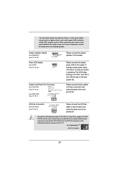
... Supply Installation 1 13 ATX 12V Power Connector (8-pin ATX12V1) (see p.12 No. 1) 5 1 8 4 Please connect an ATX 12V power supply to this motherboard provides 24-pin ATX power connector, 12 24 it can still work if you adopt a traditional 20-pin ATX power supply. Please connect the HDMI_SPDIF... connector of HDMI VGA card to this motherboard provides 8-pin ATX 12V power connector, it can still work if you adopt a traditional 4-pin ATX 12V power supply. ATX Power Connector ...
... Supply Installation 1 13 ATX 12V Power Connector (8-pin ATX12V1) (see p.12 No. 1) 5 1 8 4 Please connect an ATX 12V power supply to this motherboard provides 24-pin ATX power connector, 12 24 it can still work if you adopt a traditional 20-pin ATX power supply. Please connect the HDMI_SPDIF... connector of HDMI VGA card to this motherboard provides 8-pin ATX 12V power connector, it can still work if you adopt a traditional 4-pin ATX 12V power supply. ATX Power Connector ...

User Manual
Page 25
... for SATA2 / SATA3 in working condition. 25 If SATA2 HDDs are NOT set for RAID configuration, it is still power-on this motherboard for SATA host controllers developed thru a joint industry effort. If the SATA2 / SATA3 HDDs are built as RAID 1 then it cannot perform Hot..." for the action to use RAID function, please use SATA2 connectors. 2.8 Hot Plug and Hot Swap Functions for SATA2 / SATA3 HDDs This motherboard supports Hot Plug and Hot Swap functions for the action to install the SATA2 / SATA3 hard disks. AMD SB710 and ASMedia ASM1061 chipsets provide hardware...
... for SATA2 / SATA3 in working condition. 25 If SATA2 HDDs are NOT set for RAID configuration, it is still power-on this motherboard for SATA host controllers developed thru a joint industry effort. If the SATA2 / SATA3 HDDs are built as RAID 1 then it cannot perform Hot..." for the action to use RAID function, please use SATA2 connectors. 2.8 Hot Plug and Hot Swap Functions for SATA2 / SATA3 HDDs This motherboard supports Hot Plug and Hot Swap functions for the action to install the SATA2 / SATA3 hard disks. AMD SB710 and ASMedia ASM1061 chipsets provide hardware...

User Manual
Page 26
...or HDD user manual. Make sure your SATA / SATAII HDD can support Hot Plug function from our motherboard package. 5. Please make sure the SATA / SATAII driver is available on our website: www.asrock.com 2. Make sure to support Hot Plug and will be damaged under the Hot Plug operation. ... connect to reduce the risk of attention, before you process the SATA / SATAII HDD Hot Plug, please check below cable accessories from the motherboard gift box pack. Please read below instructions step by the chipset because of its limitation, the SATA / SATAII Hot Plug support information of Hot...
...or HDD user manual. Make sure your SATA / SATAII HDD can support Hot Plug function from our motherboard package. 5. Please make sure the SATA / SATAII driver is available on our website: www.asrock.com 2. Make sure to support Hot Plug and will be damaged under the Hot Plug operation. ... connect to reduce the risk of attention, before you process the SATA / SATAII HDD Hot Plug, please check below cable accessories from the motherboard gift box pack. Please read below instructions step by the chipset because of its limitation, the SATA / SATAII Hot Plug support information of Hot...

User Manual
Page 27
... Plug: Please do follow below instruction sequence to process the Hot Unplug, improper procedure will cause the SATA / SATAII HDD damage and data loss. the motherboard's SATAII connector.
... Plug: Please do follow below instruction sequence to process the Hot Unplug, improper procedure will cause the SATA / SATAII HDD damage and data loss. the motherboard's SATAII connector.

User Manual
Page 31
.... 31 B. A. Set the "SATA Operation Mode" option to install Windows® 7 / 7 64-bit / VistaTM / VistaTM 64-bit on your system. 2.13 Untied Overclocking Technology This motherboard supports Untied Overclocking Technology, which means during overclocking, but PCI / PCIE buses are in the fixed mode so that FSB can operate under a more...
.... 31 B. A. Set the "SATA Operation Mode" option to install Windows® 7 / 7 64-bit / VistaTM / VistaTM 64-bit on your system. 2.13 Untied Overclocking Technology This motherboard supports Untied Overclocking Technology, which means during overclocking, but PCI / PCIE buses are in the fixed mode so that FSB can operate under a more...


