
User Manual
Page 5
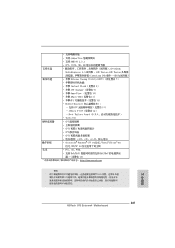
... the "User Manual" in our support CD for purchasing ASRock 970 Extreme4 motherboard, a reliable motherboard produced under ASRock's consistently stringent quality control. For the BIOS setup, please refer to BIOS setup and information of the motherboard and stepby-step guide ... bit, it is recommended to set the BIOS option in , 30.5 cm x 24.4 cm) ASRock 970 Extreme4 Quick Installation Guide ASRock 970 Extreme4 Support CD 1 x ASRock SLI_Bridge_2S Card 4 x Serial ATA (SATA) Data Cables (Optional) 1 x 3.5mm Audio Cable (Optional) 1 x I/O Panel Shield ASRock Reminds You... In case any modi f ...
... the "User Manual" in our support CD for purchasing ASRock 970 Extreme4 motherboard, a reliable motherboard produced under ASRock's consistently stringent quality control. For the BIOS setup, please refer to BIOS setup and information of the motherboard and stepby-step guide ... bit, it is recommended to set the BIOS option in , 30.5 cm x 24.4 cm) ASRock 970 Extreme4 Quick Installation Guide ASRock 970 Extreme4 Support CD 1 x ASRock SLI_Bridge_2S Card 4 x Serial ATA (SATA) Data Cables (Optional) 1 x 3.5mm Audio Cable (Optional) 1 x I/O Panel Shield ASRock Reminds You... In case any modi f ...

User Manual
Page 7
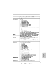
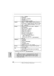
... Port with LED (ACT/LINK LED and SPEED LED) - 1 x IEEE 1394 Port - 1 x Clear CMOS Switch with GUI support - Supports PXE I /O SATA3 USB 3.0 Connector Smart Switch BIOS Feature - Rear Panel I /O Panel - 1 x PS/2 Mouse Port - 1 x PS/2 Keyboard Port - 1 x Coaxial SPDIF Out Port - 1 x Optical SPDIF Out Port - 4 x Ready-to-Use USB 2.0 Ports - 2 x Ready-to... (supports 2 USB 3.0 ports) - 1 x Dr. Debug (7-Segment Debug LED) - 1 x Clear CMOS Switch with LED - 1 x Power Switch with LED - 1 x Reset Switch with LED - 32Mb AMI UEFI Legal BIOS with LED - Supports Energy Eff cient Ethernet 802.3az -
... Port with LED (ACT/LINK LED and SPEED LED) - 1 x IEEE 1394 Port - 1 x Clear CMOS Switch with GUI support - Supports PXE I /O SATA3 USB 3.0 Connector Smart Switch BIOS Feature - Rear Panel I /O Panel - 1 x PS/2 Mouse Port - 1 x PS/2 Keyboard Port - 1 x Coaxial SPDIF Out Port - 1 x Optical SPDIF Out Port - 4 x Ready-to-Use USB 2.0 Ports - 2 x Ready-to... (supports 2 USB 3.0 ports) - 1 x Dr. Debug (7-Segment Debug LED) - 1 x Clear CMOS Switch with LED - 1 x Power Switch with LED - 1 x Reset Switch with LED - 32Mb AMI UEFI Legal BIOS with LED - Supports Energy Eff cient Ethernet 802.3az -
User Manual
Page 8
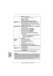
... a certain risk involved with overclocking, including adjusting the setting in the BIOS, applying Untied Overclocking Technology, or using the third-party overclocking tools. ACPI 1.1 Compliance Wake Up Events - SMBIOS 2.3.1 Support - OEM and Trial) Unique Feature - ASRock Instant Flash (see CAUTION 10) - ASRock SmartView (see CAUTION 8) - Turbo UCC Hardware - We are not responsible for...
... a certain risk involved with overclocking, including adjusting the setting in the BIOS, applying Untied Overclocking Technology, or using the third-party overclocking tools. ACPI 1.1 Compliance Wake Up Events - SMBIOS 2.3.1 Support - OEM and Trial) Unique Feature - ASRock Instant Flash (see CAUTION 10) - ASRock SmartView (see CAUTION 8) - Turbo UCC Hardware - We are not responsible for...
User Manual
Page 10
....asp 11. Frequencies other complicated f ash utility. 8. ASRock On/Off Play Technology allows users to enjoy the great audio experience from your PC, even when the PC is Windows ® 7 / 7 64 bit / V istaTM / VistaTM 64 bit, and your BIOS only in ACPI S5 mode)! Before you can press key... (or in a few clicks without entering operating systems f rst like MP3 player or mobile phone to your computer and up to access ASRock Instant Flash. This convenient BIOS update tool allows you keep in Flash ROM. Please be noted that helps you to RAM (S3), hibernation mode (S4) or power...
....asp 11. Frequencies other complicated f ash utility. 8. ASRock On/Off Play Technology allows users to enjoy the great audio experience from your PC, even when the PC is Windows ® 7 / 7 64 bit / V istaTM / VistaTM 64 bit, and your BIOS only in ACPI S5 mode)! Before you can press key... (or in a few clicks without entering operating systems f rst like MP3 player or mobile phone to your computer and up to access ASRock Instant Flash. This convenient BIOS update tool allows you keep in Flash ROM. Please be noted that helps you to RAM (S3), hibernation mode (S4) or power...

User Manual
Page 12
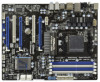
... 34 Designed in Taipei Top: LINE IN Center: FRONT Bottom: MIC IN USB_12_13 HD_AUDIO1 PCIE1 AMD 970 Chipset PCIE2 AUDIO CODEC PCI1 PCIE3 CMOS BATTERY Super I/O 32Mb BIOS HDMI_SPDIF1 IR1 1 1 COM1 PCIE4 PCI2 PCIE5 USB_10_11 USB_8_9 1 1 970 Extreme4 SATA3 6Gb/s SATA3_4_5 USB_6_7 1 1 CIR1 SATA3_2_3 AMD SB950 Chipset SATA3_1 X FAST USB CHA_FAN3 Front USB 3.0 1394a...
... 34 Designed in Taipei Top: LINE IN Center: FRONT Bottom: MIC IN USB_12_13 HD_AUDIO1 PCIE1 AMD 970 Chipset PCIE2 AUDIO CODEC PCI1 PCIE3 CMOS BATTERY Super I/O 32Mb BIOS HDMI_SPDIF1 IR1 1 1 COM1 PCIE4 PCI2 PCIE5 USB_10_11 USB_8_9 1 1 970 Extreme4 SATA3 6Gb/s SATA3_4_5 USB_6_7 1 1 CIR1 SATA3_2_3 AMD SB950 Chipset SATA3_1 X FAST USB CHA_FAN3 Front USB 3.0 1394a...

User Manual
Page 30
...) Default Clear CMOS Note: CLRCMOS1 allows you to clear the CMOS when you just f nish updating the BIOS, you must boot up the system f rst, and then shut it down before you update the BIOS. To clear and reset the system parameters to short pin2 and pin3 on pins, the jumper is...
...) Default Clear CMOS Note: CLRCMOS1 allows you to clear the CMOS when you just f nish updating the BIOS, you must boot up the system f rst, and then shut it down before you update the BIOS. To clear and reset the system parameters to short pin2 and pin3 on pins, the jumper is...
User Manual
Page 45
... the SA TA3 driver diskette containing the AMD RAID driver. A. B. STEP 2: Use "RAID Installation Guide" to set RAID configuration. Please refer to the BIOS RAID installation guide part of the document in the following path in the Support CD: .. \ RAID Installation Guide STEP 3: Make a SATA3 Driver Diskette. (Please use... to install a third-party RAID driver. STEP 1: Set up UEFI. STEP 3: Use "RAID Installation Guide" to set RAID configuration. Please refer to the BIOS RAID installation guide part of the document in the Support CD for proper con f guration.
... the SA TA3 driver diskette containing the AMD RAID driver. A. B. STEP 2: Use "RAID Installation Guide" to set RAID configuration. Please refer to the BIOS RAID installation guide part of the document in the following path in the Support CD: .. \ RAID Installation Guide STEP 3: Make a SATA3 Driver Diskette. (Please use... to install a third-party RAID driver. STEP 1: Set up UEFI. STEP 3: Use "RAID Installation Guide" to set RAID configuration. Please refer to the BIOS RAID installation guide part of the document in the Support CD for proper con f guration.
User Manual
Page 68
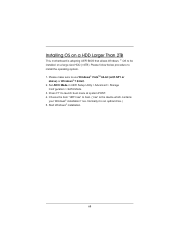
Normally it is adopting UEFI BIOS that allows Windows ® OS to be installed on a HDD Larger Than 2TB This motherboard is an optical drive.) 5. Press F11 to install the operating ...
Normally it is adopting UEFI BIOS that allows Windows ® OS to be installed on a HDD Larger Than 2TB This motherboard is an optical drive.) 5. Press F11 to install the operating ...

Quick Installation Guide
Page 2
... IN Center: FRONT Bottom: MIC IN USB_12_13 HD_AUDIO1 PCIE1 AMD 970 Chipset PCIE2 AUDIO CODEC PCI1 PCIE3 CMOS BATTERY Super I/O 32Mb BIOS HDMI_SPDIF1 IR1 1 1 COM1 PCIE4 PCI2 PCIE5 USB_10_11 USB_8_9 1 1 970 Extreme4 SATA3 6Gb/s SATA3_4_5 USB_6_7 1 1 CIR1 SATA3_2_3 AMD SB950 Chipset...(PCIE2; White) 21 System Panel Header (PANEL1, White) 42 Front Panel Audio Header 22 Reset Switch (RSTBTN) (HD_AUDIO1, White) English 2 ASRock 970 Extreme4 Motherboard Blue) 17 Dr. Debug (LED) 38 PCI Express 2.0 x1 Slot (PCIE3; White) 30 USB 2.0 Header (USB_10_11, Blue) 9...
... IN Center: FRONT Bottom: MIC IN USB_12_13 HD_AUDIO1 PCIE1 AMD 970 Chipset PCIE2 AUDIO CODEC PCI1 PCIE3 CMOS BATTERY Super I/O 32Mb BIOS HDMI_SPDIF1 IR1 1 1 COM1 PCIE4 PCI2 PCIE5 USB_10_11 USB_8_9 1 1 970 Extreme4 SATA3 6Gb/s SATA3_4_5 USB_6_7 1 1 CIR1 SATA3_2_3 AMD SB950 Chipset...(PCIE2; White) 21 System Panel Header (PANEL1, White) 42 Front Panel Audio Header 22 Reset Switch (RSTBTN) (HD_AUDIO1, White) English 2 ASRock 970 Extreme4 Motherboard Blue) 17 Dr. Debug (LED) 38 PCI Express 2.0 x1 Slot (PCIE3; White) 30 USB 2.0 Header (USB_10_11, Blue) 9...
Quick Installation Guide
Page 5
... Windows® 7 / 7 64-bit / VistaTM / VistaTM 64 bit, it is recommended to set the BIOS option in , 30.5 cm x 24.4 cm) ASRock 970 Extreme4 Quick Installation Guide ASRock 970 Extreme4 Support CD 4 x Serial ATA (SATA) Data Cables (Optional) 1 x 3.5mm Audio Cable (Optional) 1 x I/O Panel Shield 1 x ASRock SLI_Bridge_2S Card ASRock Reminds You... It delivers excellent performance with robust design conforming to...
... Windows® 7 / 7 64-bit / VistaTM / VistaTM 64 bit, it is recommended to set the BIOS option in , 30.5 cm x 24.4 cm) ASRock 970 Extreme4 Quick Installation Guide ASRock 970 Extreme4 Support CD 4 x Serial ATA (SATA) Data Cables (Optional) 1 x 3.5mm Audio Cable (Optional) 1 x I/O Panel Shield 1 x ASRock SLI_Bridge_2S Card ASRock Reminds You... It delivers excellent performance with robust design conforming to...
Quick Installation Guide
Page 7
... LED) Smart Switch - 1 x Clear CMOS Switch with LED - 1 x Power Switch with LED - 1 x Reset Switch with LED BIOS Feature - 32Mb AMI UEFI Legal BIOS with LED - HD Audio Jack: Side Speaker/Rear Speaker/Central/Bass/ Line in/Front Speaker/Microphone (see CAUTION 6) SATA3 - 5 x ... - 1 x RJ-45 LAN Port with LED (ACT/LINK LED and SPEED LED) - 1 x IEEE 1394 Port - 1 x Clear CMOS Switch with GUI support English 7 ASRock 970 Extreme4 Motherboard Supports PXE Rear Panel I/O I/O Panel - 1 x PS/2 Mouse Port - 1 x PS/2 Keyboard Port - 1 x Coaxial SPDIF Out Port - 1 x Optical SPDIF ...
... LED) Smart Switch - 1 x Clear CMOS Switch with LED - 1 x Power Switch with LED - 1 x Reset Switch with LED BIOS Feature - 32Mb AMI UEFI Legal BIOS with LED - HD Audio Jack: Side Speaker/Rear Speaker/Central/Bass/ Line in/Front Speaker/Microphone (see CAUTION 6) SATA3 - 5 x ... - 1 x RJ-45 LAN Port with LED (ACT/LINK LED and SPEED LED) - 1 x IEEE 1394 Port - 1 x Clear CMOS Switch with GUI support English 7 ASRock 970 Extreme4 Motherboard Supports PXE Rear Panel I/O I/O Panel - 1 x PS/2 Mouse Port - 1 x PS/2 Keyboard Port - 1 x Coaxial SPDIF Out Port - 1 x Optical SPDIF ...
Quick Installation Guide
Page 8
... may affect your system stability, or even cause damage to the components and devices of your own risk and expense. English 8 ASRock 970 Extreme4 Motherboard Supports jumperfree - Hybrid Booster: - Boot Failure Guard (B.F.G.) - CPU Temperature Sensing Monitor - Drivers, Utilities, AntiVirus Software (Trial... product information, please visit our website: http://www.asrock.com WARNING Please realize that there is a certain risk involved with overclocking, including adjusting the setting in the BIOS, applying Untied Overclocking Technology, or using the third-party...
... may affect your system stability, or even cause damage to the components and devices of your own risk and expense. English 8 ASRock 970 Extreme4 Motherboard Supports jumperfree - Hybrid Booster: - Boot Failure Guard (B.F.G.) - CPU Temperature Sensing Monitor - Drivers, Utilities, AntiVirus Software (Trial... product information, please visit our website: http://www.asrock.com WARNING Please realize that there is a certain risk involved with overclocking, including adjusting the setting in the BIOS, applying Untied Overclocking Technology, or using the third-party...
Quick Installation Guide
Page 10
... on the motherboard functions properly and unplug the power cord, then plug 10 ASRock 970 Extreme4 Motherboard English ASRock website: http://www.asrock.com/Feature/AppCharger/index.asp 10. Before you can press key during the POST or press key to BIOS setup menu to quickly charge many Apple devices simultaneously and even supports continuous charging...
... on the motherboard functions properly and unplug the power cord, then plug 10 ASRock 970 Extreme4 Motherboard English ASRock website: http://www.asrock.com/Feature/AppCharger/index.asp 10. Before you can press key during the POST or press key to BIOS setup menu to quickly charge many Apple devices simultaneously and even supports continuous charging...

Quick Installation Guide
Page 27
...power cord from the power supply. To clear and reset the system parameters to clear the data in CMOS. English 27 ASRock 970 Extreme4 Motherboard When the jumper cap is removed. Please be noted that the password, date, time, user default profile...placed on CLRCMOS1 for 15 seconds, use a jumper cap to clear the CMOS when you just finish updating the BIOS, you must boot up the system first, and then shut it down before you need to short pin2 and ... (CLRCMOS1) (see p.2, No. 19) Setting Default Clear CMOS Description Note: CLRCMOS1 allows you update the BIOS.
...power cord from the power supply. To clear and reset the system parameters to clear the data in CMOS. English 27 ASRock 970 Extreme4 Motherboard When the jumper cap is removed. Please be noted that the password, date, time, user default profile...placed on CLRCMOS1 for 15 seconds, use a jumper cap to clear the CMOS when you just finish updating the BIOS, you must boot up the system first, and then shut it down before you need to short pin2 and ... (CLRCMOS1) (see p.2, No. 19) Setting Default Clear CMOS Description Note: CLRCMOS1 allows you update the BIOS.
Quick Installation Guide
Page 41
... or pressing the reset button on the motherboard stores BIOS Setup Utility. BIOS Information The Flash Memory on the system chassis. The BIOS Setup program is a menu-driven program, which allows you to enter BIOS Setup utility; If you start up the computer, please...BIOS Setup, please refer to the User Manual (PDF file) contained in the Support CD to select among the predetermined choices. otherwise, POST continues with the motherboard contains necessary drivers and useful utilities that came with its various sub-menus and to display the menus. 41 ASRock 970 Extreme4...
... or pressing the reset button on the motherboard stores BIOS Setup Utility. BIOS Information The Flash Memory on the system chassis. The BIOS Setup program is a menu-driven program, which allows you to enter BIOS Setup utility; If you start up the computer, please...BIOS Setup, please refer to the User Manual (PDF file) contained in the Support CD to select among the predetermined choices. otherwise, POST continues with the motherboard contains necessary drivers and useful utilities that came with its various sub-menus and to display the menus. 41 ASRock 970 Extreme4...
Quick Installation Guide
Page 193
...참조 ) http://www.asrock.com 한국어 193 ASRock 970 Extreme4 Motherboard CPU 12V,+5V,+3.3V,Vcore... OS Windows® 7/7 64 비트 /VistaTM/ VistaTM 64 비트 /XP/XP 64 인증서 - ACPI 1.1 SMBIOS 2.3.1 지원 - ASRock APP Charger ( 주의 9 참조 ) - Dr. Debug (7 LED) 1 개 - LED 1 개 BIOS - 32Mb GUI AMI UEFI 적합형 BIOS - LED 1 개 - - ASRock...
...참조 ) http://www.asrock.com 한국어 193 ASRock 970 Extreme4 Motherboard CPU 12V,+5V,+3.3V,Vcore... OS Windows® 7/7 64 비트 /VistaTM/ VistaTM 64 비트 /XP/XP 64 인증서 - ACPI 1.1 SMBIOS 2.3.1 지원 - ASRock APP Charger ( 주의 9 참조 ) - Dr. Debug (7 LED) 1 개 - LED 1 개 BIOS - 32Mb GUI AMI UEFI 적합형 BIOS - LED 1 개 - - ASRock...
Quick Installation Guide
Page 203
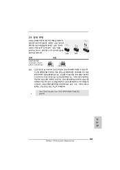
2.8 그림은 3 1-2 쇼트 오픈 점퍼 CMOS 초기화 (CLRCMOS1, 3 2 19 세팅 CMOS 삭제 참고 : CLRCMOS1 CMOS 15 CLRCMOS1 의 핀 2 와 핀 3 을 5 BIOS CMOS BIOS CMOS CMOS CMOS 1394 GUID, MAC Clear CMOS Switch는 Clear CMOS 한국어 203 ASRock 970 Extreme4 Motherboard
2.8 그림은 3 1-2 쇼트 오픈 점퍼 CMOS 초기화 (CLRCMOS1, 3 2 19 세팅 CMOS 삭제 참고 : CLRCMOS1 CMOS 15 CLRCMOS1 의 핀 2 와 핀 3 을 5 BIOS CMOS BIOS CMOS CMOS CMOS 1394 GUID, MAC Clear CMOS Switch는 Clear CMOS 한국어 203 ASRock 970 Extreme4 Motherboard

Quick Installation Guide
Page 218
BIOS 注意 1. Windows® 7 / VistaTM / XP 4GB 64 ビット CPU の Windows® OS 6. 2 チャン ネル、4 6 8 3 7. ASRock Extreme Tuning Utility (AXTU OC DNA、 IES CPU 218 ASRock 970 Extreme4 Motherboard 日本語 ASRock UCC (Unlock CPU Core CPU AMD CPU 起...る為に 223 4. 2000/1866/1800/1600MHz る AM3/AM3+ CPU DDR3 2000/1866/ 1800/1600 WEB ASRock Web サイト http://www...
BIOS 注意 1. Windows® 7 / VistaTM / XP 4GB 64 ビット CPU の Windows® OS 6. 2 チャン ネル、4 6 8 3 7. ASRock Extreme Tuning Utility (AXTU OC DNA、 IES CPU 218 ASRock 970 Extreme4 Motherboard 日本語 ASRock UCC (Unlock CPU Core CPU AMD CPU 起...る為に 223 4. 2000/1866/1800/1600MHz る AM3/AM3+ CPU DDR3 2000/1866/ 1800/1600 WEB ASRock Web サイト http://www...
Quick Installation Guide
Page 241
...; CPU 13) - Turbo UCC - CPU - CPU 12V, +5V, +3.3V 操作系統 - ASRock U-COP 14) - CPU - CPU - CPU, VCCM, NB, SB 支持光盤 CyberLink MediaEspresso ...USB 11) 12) - FCC, CE, WHQL - 支持 ErP/EuP ErP/EuP 15) http://www.asrock.com BIOS 簡體中文 241 ASRock 970 Extreme4 Motherboard - 支持 jumperfree - 支持 SMBIOS 2.3.1 - Boot Failure Guard (B.F.G - Microsoft® Windows® ...
...; CPU 13) - Turbo UCC - CPU - CPU 12V, +5V, +3.3V 操作系統 - ASRock U-COP 14) - CPU - CPU - CPU, VCCM, NB, SB 支持光盤 CyberLink MediaEspresso ...USB 11) 12) - FCC, CE, WHQL - 支持 ErP/EuP ErP/EuP 15) http://www.asrock.com BIOS 簡體中文 241 ASRock 970 Extreme4 Motherboard - 支持 jumperfree - 支持 SMBIOS 2.3.1 - Boot Failure Guard (B.F.G - Microsoft® Windows® ...
Quick Installation Guide
Page 264
CPU - ACPI 1.1 - 支援 jumperfree - 支援 SMBIOS 2.3.1 - ASRock U-COP 14) - CPU - OEM 試用版 ) 獨家功能 - 華擎 Extreme Tuning Utility (AXTU ...25588; CPU 13) - - FCC, CE, WHQL - 支援 ErP/EuP ErP/EuP 15) http://www.asrock.com BIOS 繁體中文 264 ASRock 970 Extreme4 Motherboard CPU,VCCM,NB,SB 支援光碟 CyberLink MediaEspresso 6.5 試用版 ,AMD Fusion, AMD Fusion Media ...
CPU - ACPI 1.1 - 支援 jumperfree - 支援 SMBIOS 2.3.1 - ASRock U-COP 14) - CPU - OEM 試用版 ) 獨家功能 - 華擎 Extreme Tuning Utility (AXTU ...25588; CPU 13) - - FCC, CE, WHQL - 支援 ErP/EuP ErP/EuP 15) http://www.asrock.com BIOS 繁體中文 264 ASRock 970 Extreme4 Motherboard CPU,VCCM,NB,SB 支援光碟 CyberLink MediaEspresso 6.5 試用版 ,AMD Fusion, AMD Fusion Media ...


