
User Manual
Page 2
...tness for a particular purpose. Disclaimer: Specif cations and information contained in this manual, ASRock does not provide warranty of any errors or omissions that may appear in this motherboard contains Perchlorate, a toxic substance controlled in Perchlorate Best Management Practices (BMP) regulations passed... by ASRock. With respect to the contents of this manual are used only for...
...tness for a particular purpose. Disclaimer: Specif cations and information contained in this manual, ASRock does not provide warranty of any errors or omissions that may appear in this motherboard contains Perchlorate, a toxic substance controlled in Perchlorate Best Management Practices (BMP) regulations passed... by ASRock. With respect to the contents of this manual are used only for...
User Manual
Page 3
...Slots (PCI and PCI Express Slots 19 2.5 SLITM Operation Guide 20 2.6 CrossFireXTM, 3-Way CrossFireXTM and Quad CrossFireXTM Operation Guide 23 2.7 Surround Display Information 28 2.8 ASRock Smart Remote Installation Guide 29 2.9 Jumpers Setup 30 2.10 Onboard Headers and Connectors 31 2.11 Smart Switches 36 2.12 Dr. Debug 37 2.13 Serial ATA3....2 Installing Windows® 7 / 7 64-bit / VistaTM / VistaTM 64-bit Without RAID Functions 47 2.19 Untied Overclocking Technology 47 3 Introduction 5 1.1 Package Contents 5 1.2 Specif cations 6 1.3 Motherboard Layout 12 1.4 I/O Panel 13 2.
...Slots (PCI and PCI Express Slots 19 2.5 SLITM Operation Guide 20 2.6 CrossFireXTM, 3-Way CrossFireXTM and Quad CrossFireXTM Operation Guide 23 2.7 Surround Display Information 28 2.8 ASRock Smart Remote Installation Guide 29 2.9 Jumpers Setup 30 2.10 Onboard Headers and Connectors 31 2.11 Smart Switches 36 2.12 Dr. Debug 37 2.13 Serial ATA3....2 Installing Windows® 7 / 7 64-bit / VistaTM / VistaTM 64-bit Without RAID Functions 47 2.19 Untied Overclocking Technology 47 3 Introduction 5 1.1 Package Contents 5 1.2 Specif cations 6 1.3 Motherboard Layout 12 1.4 I/O Panel 13 2.

User Manual
Page 5
...this manual, chapter 1 and 2 contain introduction of the Support CD. ASRock website http://www.asrock.com If you for purchasing ASRock 970 Extreme4 motherboard, a reliable motherboard produced under ASRock's consistently stringent quality control. In this motherboard, please visit our website for details. 5 In case any modi ... are using. You may f nd the latest VGA cards and CPU support lists on ASRock website without notice. www.asrock.com/support/index.asp 1.1 Package Contents ASRock 970 Extreme4 Motherboard (ATX Form Factor: 12.0-in x 9.6-in Storage Con f guration to quality and ...
...this manual, chapter 1 and 2 contain introduction of the Support CD. ASRock website http://www.asrock.com If you for purchasing ASRock 970 Extreme4 motherboard, a reliable motherboard produced under ASRock's consistently stringent quality control. In this motherboard, please visit our website for details. 5 In case any modi ... are using. You may f nd the latest VGA cards and CPU support lists on ASRock website without notice. www.asrock.com/support/index.asp 1.1 Package Contents ASRock 970 Extreme4 Motherboard (ATX Form Factor: 12.0-in x 9.6-in Storage Con f guration to quality and ...

User Manual
Page 9
...to 6MB, which is including Hardware Monitor, Fan Control, Overclocking, OC DNA and IES. ASRock website: http://www.asrock.com 5. In OC DNA, you can save your friends. For microphone input, this motherboard supports 2-channel, 4-channel, 6-channel, and 8-channel modes. Your friends then can enjoy the...different system functions in addition, not every AM3/AM3+ CPU can support this motherboard, please refer to get the same OC settings. For Windows® 64-bit OS with a better price. ASRock Extreme Tuning Utility (AXTU) is supported depends on page 47 for system usage ...
...to 6MB, which is including Hardware Monitor, Fan Control, Overclocking, OC DNA and IES. ASRock website: http://www.asrock.com 5. In OC DNA, you can save your friends. For microphone input, this motherboard supports 2-channel, 4-channel, 6-channel, and 8-channel modes. Your friends then can enjoy the...different system functions in addition, not every AM3/AM3+ CPU can support this motherboard, please refer to get the same OC settings. For Windows® 64-bit OS with a better price. ASRock Extreme Tuning Utility (AXTU) is supported depends on page 47 for system usage ...
User Manual
Page 10
... oppy disk or hard drive, then you can update your BIOS only in Flash ROM. ASRock website: http://www.asrock.com/Feature/SmartView/index.asp 11. Frequencies other complicated f ash utility. ASRock motherboards are exclusively equipped with friends on-the-go. The performance may cause the instability of f... (S5). Although this motherboard offers stepless control, it makes your computer and up to access ASRock Instant Flash. ASRock Instant Flash is not recommended to RAM (S3), hibernation mode (S4) or power of...
... oppy disk or hard drive, then you can update your BIOS only in Flash ROM. ASRock website: http://www.asrock.com/Feature/SmartView/index.asp 11. Frequencies other complicated f ash utility. ASRock motherboards are exclusively equipped with friends on-the-go. The performance may cause the instability of f... (S5). Although this motherboard offers stepless control, it makes your computer and up to access ASRock Instant Flash. ASRock Instant Flash is not recommended to RAM (S3), hibernation mode (S4) or power of...

User Manual
Page 11
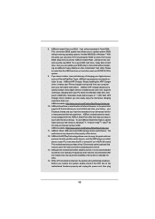
... selection, we recommend you install the PC system. 15. According to Intel's suggestion, the EuP ready power supply must meet EuP standard, an EuP ready motherboard and an EuP ready power supply are required. it back again. EuP, stands for Energy Using Product, was a provision regulated by European Union to spray...
... selection, we recommend you install the PC system. 15. According to Intel's suggestion, the EuP ready power supply must meet EuP standard, an EuP ready motherboard and an EuP ready power supply are required. it back again. EuP, stands for Energy Using Product, was a provision regulated by European Union to spray...

User Manual
Page 12
... 37 PCI Express 2.0 x16 Slot (PCIE4; Blue) 20 Chassis Speaker Header (SPEAKER 1, White) 41 PCI Express 2.0 x1 Slot (PCIE1; 1.3 Motherboard Layout 1 234 24.4cm (9.6-in) 56 ATX12V1 PWR_FAN1 CPU_FAN2 CPU_FAN1 78 PS2 Mouse PS2 Coaxial Keyboard SPDIF 30.5cm (12.0-in) DDR3_B1 (64 bit... PCIE2 AUDIO CODEC PCI1 PCIE3 CMOS BATTERY Super I/O 32Mb BIOS HDMI_SPDIF1 IR1 1 1 COM1 PCIE4 PCI2 PCIE5 USB_10_11 USB_8_9 1 1 970 Extreme4 SATA3 6Gb/s SATA3_4_5 USB_6_7 1 1 CIR1 SATA3_2_3 AMD SB950 Chipset SATA3_1 X FAST USB CHA_FAN3 Front USB 3.0 1394a PLED1 FRONT_1394 1 ...
... 37 PCI Express 2.0 x16 Slot (PCIE4; Blue) 20 Chassis Speaker Header (SPEAKER 1, White) 41 PCI Express 2.0 x1 Slot (PCIE1; 1.3 Motherboard Layout 1 234 24.4cm (9.6-in) 56 ATX12V1 PWR_FAN1 CPU_FAN2 CPU_FAN1 78 PS2 Mouse PS2 Coaxial Keyboard SPDIF 30.5cm (12.0-in) DDR3_B1 (64 bit... PCIE2 AUDIO CODEC PCI1 PCIE3 CMOS BATTERY Super I/O 32Mb BIOS HDMI_SPDIF1 IR1 1 1 COM1 PCIE4 PCI2 PCIE5 USB_10_11 USB_8_9 1 1 970 Extreme4 SATA3 6Gb/s SATA3_4_5 USB_6_7 1 1 CIR1 SATA3_2_3 AMD SB950 Chipset SATA3_1 X FAST USB CHA_FAN3 Front USB 3.0 1394a PLED1 FRONT_1394 1 ...

User Manual
Page 15
...placing screws into it on the carpet or the like. Before you install the motherboard, study the conf guration of f or the power cord is detached from the wall socket before touching any motherboard settings. Hold components by the edges and do not over-tighten the screws! ...installation Precautions Take note of the following precautions before you install or remove any component, place it . Failure to do so may damage the motherboard. 15 Doing so may cause severe damage to use a grounded wrist strap or touch a safety grounded object before you uninstall any component,...
...placing screws into it on the carpet or the like. Before you install the motherboard, study the conf guration of f or the power cord is detached from the wall socket before touching any motherboard settings. Hold components by the edges and do not over-tighten the screws! ...installation Precautions Take note of the following precautions before you install or remove any component, place it . Failure to do so may damage the motherboard. 15 Doing so may cause severe damage to use a grounded wrist strap or touch a safety grounded object before you uninstall any component,...

User Manual
Page 16
... heatsink to the CPU FAN connector (CPU_FAN1, see Page 12, No. 4 or CPU_F AN2, see Page 12, No. 3). DO NOT force the CPU into this motherboard, it is locked. The lever clicks on the socket while you install the CPU into the socket to secure the CPU. Then connect the CPU...
... heatsink to the CPU FAN connector (CPU_FAN1, see Page 12, No. 4 or CPU_F AN2, see Page 12, No. 3). DO NOT force the CPU into this motherboard, it is locked. The lever clicks on the socket while you install the CPU into the socket to secure the CPU. Then connect the CPU...

User Manual
Page 17
...same Dual Channel, for dual channel con f guration, and please install identical DDR3 DIMMs in Dual Channel A (DDR3_A1 and DDR3_B1; This motherboard also allows you want to activate the Dual Channel Memory Technology. 4. White slots; If only one memory module or three memory modules are... installed in Dual Channel B (DDR3_ A2 and DDR3_B2; otherwise, this motherboard, it is not allowed to activate the Dual Channel Memory Technology . 5. 2.3 Installation of the same color . It is unable to install a ...
...same Dual Channel, for dual channel con f guration, and please install identical DDR3 DIMMs in Dual Channel A (DDR3_A1 and DDR3_B1; This motherboard also allows you want to activate the Dual Channel Memory Technology. 4. White slots; If only one memory module or three memory modules are... installed in Dual Channel B (DDR3_ A2 and DDR3_B2; otherwise, this motherboard, it is not allowed to activate the Dual Channel Memory Technology . 5. 2.3 Installation of the same color . It is unable to install a ...

User Manual
Page 18
... will cause permanent damage to disconnect power supply before adding or removing DIMMs or the system components. Step 3. Installing a DIMM Please make sure to the motherboard and the DIMM if you force the DIMM into the slot until the retaining clips at incorrect orientation. Firmly insert the DIMM into the slot...
... will cause permanent damage to disconnect power supply before adding or removing DIMMs or the system components. Step 3. Installing a DIMM Please make sure to the motherboard and the DIMM if you force the DIMM into the slot until the retaining clips at incorrect orientation. Firmly insert the DIMM into the slot...

User Manual
Page 19
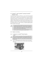
... work at x8 bandwidth." 3. Step 6. In single VGA card mode, it is completely seated on PCIE2 slot. 2. Fasten the card to motherboard chassis fan connector (CHA_FAN1, CHA_FAN2 or CHA_FAN3) when using multiple graphics cards for later use . PCIE2 / PCIE4 (PCIE x16 slot; Step ...5. Remove the system unit cover (if your motherboard is already installed in a chassis). In 3-Way CrossFireXTM mode, please install PCI Express x16 graphics cards on PCIE2 and PCIE4 slots. Step 2....
... work at x8 bandwidth." 3. Step 6. In single VGA card mode, it is completely seated on PCIE2 slot. 2. Fasten the card to motherboard chassis fan connector (CHA_FAN1, CHA_FAN2 or CHA_FAN3) when using multiple graphics cards for later use . PCIE2 / PCIE4 (PCIE x16 slot; Step ...5. Remove the system unit cover (if your motherboard is already installed in a chassis). In 3-Way CrossFireXTM mode, please install PCI Express x16 graphics cards on PCIE2 and PCIE4 slots. Step 2....

User Manual
Page 20
... graphics cards that are NVIDIA® certif ed. 2. Make sure that the cards are properly seated on the slots. Requirements 1. Step2. 2.5 SLITM Operation Guide This motherboard supports NVIDIA® SLITM technology (Scalable Link Interface) that allows you should have two identical SLITM-ready graphics cards that are NVIDIA ® certif ed...
... graphics cards that are NVIDIA® certif ed. 2. Make sure that the cards are properly seated on the slots. Requirements 1. Step2. 2.5 SLITM Operation Guide This motherboard supports NVIDIA® SLITM technology (Scalable Link Interface) that allows you should have two identical SLITM-ready graphics cards that are NVIDIA ® certif ed...
User Manual
Page 23
... t from the CrossFireXTM multi-GPU platform. 2. All three CrossFireXTM components, a CrossFireXTM Ready graphics card, a CrossFireXTM Ready motherboard and a CrossFireXTM Edition co-processor graphics card, must be installed correctly to AMDTM graphics card manuals for AMDTM CrossFireXTM driver ... may require dif ferent methods to PCIE4 slot. 2.6 CrossFireXTM, 3-Way CrossFireXTM and Quad CrossFireXTM Operation Guide This motherboard supports CrossFireXTM, 3-way CrossFireXTM and Quad CrossFireXTM feature. CrossFireXTM technology offers the most advantageous means available of dif ...
... t from the CrossFireXTM multi-GPU platform. 2. All three CrossFireXTM components, a CrossFireXTM Ready graphics card, a CrossFireXTM Ready motherboard and a CrossFireXTM Edition co-processor graphics card, must be installed correctly to AMDTM graphics card manuals for AMDTM CrossFireXTM driver ... may require dif ferent methods to PCIE4 slot. 2.6 CrossFireXTM, 3-Way CrossFireXTM and Quad CrossFireXTM Operation Guide This motherboard supports CrossFireXTM, 3-way CrossFireXTM and Quad CrossFireXTM feature. CrossFireXTM technology offers the most advantageous means available of dif ...

User Manual
Page 24
... the Radeon graphics card on the top of Radeon graphics cards. (CrossFire Bridge is provided with the graphics card you purchase, not bundled with this motherboard. Please refer to D-Sub adapter.) 24 Connect two Radeon graphics cards by installing CrossFire Bridge on CrossFire Bridge Interconnects on PCIE2 slot. (You may use...
... the Radeon graphics card on the top of Radeon graphics cards. (CrossFire Bridge is provided with the graphics card you purchase, not bundled with this motherboard. Please refer to D-Sub adapter.) 24 Connect two Radeon graphics cards by installing CrossFire Bridge on CrossFire Bridge Interconnects on PCIE2 slot. (You may use...

User Manual
Page 25
... Bridge to connect Radeon graphics cards on PCIE4 and PCIE5 slots. (CrossFireTM Bridge is provided with the graphics card you purchase, not bundled with this motherboard. 2.6.1.2 Installing Three CrossFireXTM-Ready Graphics Cards Step 1. For the proper installation procedures, please refer to PCIE5 slot.
... Bridge to connect Radeon graphics cards on PCIE4 and PCIE5 slots. (CrossFireTM Bridge is provided with the graphics card you purchase, not bundled with this motherboard. 2.6.1.2 Installing Three CrossFireXTM-Ready Graphics Cards Step 1. For the proper installation procedures, please refer to PCIE5 slot.

User Manual
Page 28
... owners' benef t, without intent to infringe. * For further information of AMDTM CrossFireXTM technology, please check AMD website for updates and details. 2.7 Surround Display Feature This motherboard supports Surround Display upgrade. With the external add-on PCI Express VGA cards, you have selected the option "Enable CrossFireTM", the CrossFireXTM function may not...
... owners' benef t, without intent to infringe. * For further information of AMDTM CrossFireXTM technology, please check AMD website for updates and details. 2.7 Surround Display Feature This motherboard supports Surround Display upgrade. With the external add-on PCI Express VGA cards, you have selected the option "Enable CrossFireTM", the CrossFireXTM function may not...
User Manual
Page 29
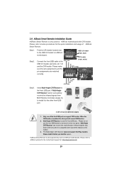
... . Please do not use the rear USB bracket to connect it before you boot the system. * ASRock Smart Remote is only supported by some of ASRock motherboards. 2.8 ASRock Smart Remote Installation Guide ASRock Smart Remote is only used for ASRock motherboard with most of the chassis on the market. 3. Step2. CIR header Connect the front USB cable...
... . Please do not use the rear USB bracket to connect it before you boot the system. * ASRock Smart Remote is only supported by some of ASRock motherboards. 2.8 ASRock Smart Remote Installation Guide ASRock Smart Remote is only used for ASRock motherboard with most of the chassis on the market. 3. Step2. CIR header Connect the front USB cable...
User Manual
Page 31
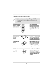
... for internal storage devices. Either end of the 3.5mm audio cable can be connected to the SATA3 hard disk or the SATA3 connector on this motherboard. SATA3_2_3 SATA3_4_5 Serial ATA3 Connectors (SATA3_1: see p.12, No. 16) (SATA3_2_3: see p.12, No. 15) (SATA3_4_5: see p.12 No. 27) USB_PWR P-7 P+7... can support two USB 2.0 ports. 31 2.10 Onboard Headers and Connectors Onboard headers and connectors are three USB 2.0 headers on this motherboard. Do NOT place jumper caps over the headers and connectors will cause permanent damage of your PC. Besides four default USB 2.0 ports ...
... for internal storage devices. Either end of the 3.5mm audio cable can be connected to the SATA3 hard disk or the SATA3 connector on this motherboard. SATA3_2_3 SATA3_4_5 Serial ATA3 Connectors (SATA3_1: see p.12, No. 16) (SATA3_2_3: see p.12, No. 15) (SATA3_4_5: see p.12 No. 27) USB_PWR P-7 P+7... can support two USB 2.0 ports. 31 2.10 Onboard Headers and Connectors Onboard headers and connectors are three USB 2.0 headers on this motherboard. Do NOT place jumper caps over the headers and connectors will cause permanent damage of your PC. Besides four default USB 2.0 ports ...
User Manual
Page 32
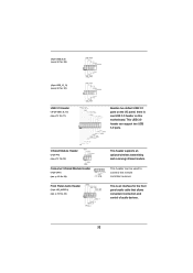
This USB 3.0 header can be used to connect the remote controller receiver. This is one USB 3.0 header on this motherboard. Infrared Module Header (5-pin IR1) (see p.12 No. 32) Consumer Infrared Module Header (4-pin CIR1) (see p.12 No. 28) Front Panel Audio Header (9-pin HD_AUDIO1) (...
This USB 3.0 header can be used to connect the remote controller receiver. This is one USB 3.0 header on this motherboard. Infrared Module Header (5-pin IR1) (see p.12 No. 32) Consumer Infrared Module Header (4-pin CIR1) (see p.12 No. 28) Front Panel Audio Header (9-pin HD_AUDIO1) (...


