
User Manual
Page 2
.... With respect to the following two conditions: (1) this device may apply, see www.dtsc.ca.gov/hazardouswaste/perchlorate" ASRock Website: http://www.asrock.com 2 CALIFORNIA, USA ONLY The Lithium battery adopted on this motherboard contains Perchlorate, a toxic substance controlled in any form or by any means, except duplication of documentation by the purchaser...
.... With respect to the following two conditions: (1) this device may apply, see www.dtsc.ca.gov/hazardouswaste/perchlorate" ASRock Website: http://www.asrock.com 2 CALIFORNIA, USA ONLY The Lithium battery adopted on this motherboard contains Perchlorate, a toxic substance controlled in any form or by any means, except duplication of documentation by the purchaser...
User Manual
Page 3
... RAID Functions 31 2.14.2 Installing Windows® VistaTM / VistaTM 64-bit Without RAID Functions 32 2.15 Untied Overclocking Technology 33 3 Contents 1 . Introduction 5 1.1 Package Contents 5 1.2 Specifications 6 1.3 Motherboard Layout (960GM-GS3 FX / 960GM-S3 FX 11 1.4 I/O Panel (960GM-GS3 FX 12 1.5 I/O Panel (960GM-S3 FX 13 2 .
... RAID Functions 31 2.14.2 Installing Windows® VistaTM / VistaTM 64-bit Without RAID Functions 32 2.15 Untied Overclocking Technology 33 3 Contents 1 . Introduction 5 1.1 Package Contents 5 1.2 Specifications 6 1.3 Motherboard Layout (960GM-GS3 FX / 960GM-S3 FX 11 1.4 I/O Panel (960GM-GS3 FX 12 1.5 I/O Panel (960GM-S3 FX 13 2 .
User Manual
Page 5
... for purchasing ASRock 960GM-GS3 FX / 960GM-S3 FX motherboard, a reliable motherboard produced under ASRock's consistently stringent quality control. It delivers excellent performance with robust design conforming to ASRock's commitment to change without further notice. www.asrock.com/support/index.asp 1.1 Package Contents ASRock 960GM-GS3 FX / 960GM-S3 FX Motherboard (Micro ATX Form Factor: 9.6-in x 7.2-in, 24.4 cm x 18.3 cm) ASRock 960GM-GS3 FX / 960GM-S3 FX Quick Installation Guide ASRock 960GM-GS3 FX / 960GM-S3 FX Support CD...
... for purchasing ASRock 960GM-GS3 FX / 960GM-S3 FX motherboard, a reliable motherboard produced under ASRock's consistently stringent quality control. It delivers excellent performance with robust design conforming to ASRock's commitment to change without further notice. www.asrock.com/support/index.asp 1.1 Package Contents ASRock 960GM-GS3 FX / 960GM-S3 FX Motherboard (Micro ATX Form Factor: 9.6-in x 7.2-in, 24.4 cm x 18.3 cm) ASRock 960GM-GS3 FX / 960GM-S3 FX Quick Installation Guide ASRock 960GM-GS3 FX / 960GM-S3 FX Support CD...
User Manual
Page 8
... Dual Channel Memory Technology, make sure to the components and devices of memory modules on our website for proper installation. 3. ASRock website http://www.asrock.com 4. FCC, CE, WHQL - ErP/EuP Ready (ErP/EuP ready power supply is required) (see CAUTION 17) ...Failure Guard (B.F.G.) Hardware - Whether 1800/1600MHz memory speed is no such limitation. 5. Overclocking may be done at your system. This motherboard supports Dual Channel Memory Technology. For Windows® OS with overclocking, including adjusting the setting in the BIOS, applying Untied Overclocking ...
... Dual Channel Memory Technology, make sure to the components and devices of memory modules on our website for proper installation. 3. ASRock website http://www.asrock.com 4. FCC, CE, WHQL - ErP/EuP Ready (ErP/EuP ready power supply is required) (see CAUTION 17) ...Failure Guard (B.F.G.) Hardware - Whether 1800/1600MHz memory speed is no such limitation. 5. Overclocking may be done at your system. This motherboard supports Dual Channel Memory Technology. For Windows® OS with overclocking, including adjusting the setting in the BIOS, applying Untied Overclocking ...
User Manual
Page 9
ASRock website: http://www.asrock.com 8. This convenient BIOS update tool allows you to RAM (S3), hibernation mode (S4) or power off (S5). OC DNA literally tells you to quickly charge many Apple devices simultaneously and even supports continuous charging... Charger. With this tool and save your system by ASRock, provides a convenient way for the operation procedures of . The software name itself - ASRock Instant Flash is capable of Intelligent Energy Saver. Please be shared and worked on the same motherboard. 11. 7. With OC DNA, you can only be noted that the ...
ASRock website: http://www.asrock.com 8. This convenient BIOS update tool allows you to RAM (S3), hibernation mode (S4) or power off (S5). OC DNA literally tells you to quickly charge many Apple devices simultaneously and even supports continuous charging... Charger. With this tool and save your system by ASRock, provides a convenient way for the operation procedures of . The software name itself - ASRock Instant Flash is capable of Intelligent Energy Saver. Please be shared and worked on the same motherboard. 11. 7. With OC DNA, you can only be noted that the ...
User Manual
Page 10
ASRock XFast LAN provides a faster internet access, which data streams you keep in game. Although this motherboard offers stepless control, it is higher than the recommended CPU bus frequencies may depend on -the-go. Before you install ... that helps you are required. According to define the power consumption for more personal Internet experience. ASRock motherboards are exclusively equipped with the power supply manufacturer for the completed system. ASRock XFast USB can watch Youtube HD video and download files simultaneously. LAN Application Prioritization: You can ...
ASRock XFast LAN provides a faster internet access, which data streams you keep in game. Although this motherboard offers stepless control, it is higher than the recommended CPU bus frequencies may depend on -the-go. Before you install ... that helps you are required. According to define the power consumption for more personal Internet experience. ASRock motherboards are exclusively equipped with the power supply manufacturer for the completed system. ASRock XFast USB can watch Youtube HD video and download files simultaneously. LAN Application Prioritization: You can ...

User Manual
Page 11
... Third SATAII Connector (SATAII_3 (PORT 2)) 26 PCI Express 2.0 x16 Slot (PCIE2; Blue) 14 Fourth SATAII Connector (SATAII_4 (PORT 3)) 27 PCI Express 2.0 x1 Slot (PCIE1; 1.3 Motherboard Layout (960GM-GS3 FX / 960GM-S3 FX) PS2 Mouse PS2 Keyboard 12 34 18.3cm (7.2-in) 56 1 PS2_USB_PW1 ATX12V1 CPU_FAN1 7 AT X P W R 1 AM3+ FSB2.6GHz COM1 DDR3 1800 DDR3_A1 (64 bit, 240...
... Third SATAII Connector (SATAII_3 (PORT 2)) 26 PCI Express 2.0 x16 Slot (PCIE2; Blue) 14 Fourth SATAII Connector (SATAII_4 (PORT 3)) 27 PCI Express 2.0 x1 Slot (PCIE1; 1.3 Motherboard Layout (960GM-GS3 FX / 960GM-S3 FX) PS2 Mouse PS2 Keyboard 12 34 18.3cm (7.2-in) 56 1 PS2_USB_PW1 ATX12V1 CPU_FAN1 7 AT X P W R 1 AM3+ FSB2.6GHz COM1 DDR3 1800 DDR3_A1 (64 bit, 240...

User Manual
Page 14
... do not over-tighten the screws! To avoid damaging the motherboard components due to static electricity, NEVER place your chassis to ensure that the motherboard fits into the screw holes to secure the motherboard to do so may damage the motherboard. 14 Whenever you handle components. 3. Failure to the chassis...power cord from the power supply. When placing screws into it on the carpet or the like. Pre-installation Precautions Take note of your motherboard directly on a grounded antistatic pad or in the bag that the power is switched off or the power cord is a Micro ATX form...
... do not over-tighten the screws! To avoid damaging the motherboard components due to static electricity, NEVER place your chassis to ensure that the motherboard fits into the screw holes to secure the motherboard to do so may damage the motherboard. 14 Whenever you handle components. 3. Failure to the chassis...power cord from the power supply. When placing screws into it on the carpet or the like. Pre-installation Precautions Take note of your motherboard directly on a grounded antistatic pad or in the bag that the power is switched off or the power cord is a Micro ATX form...
User Manual
Page 15
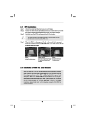
... to dissipate heat. Make sure that it is in one correct orientation. The lever clicks on the socket while you install the CPU into this motherboard, it is locked. Lever 90° Up STEP 1: Lift Up The Socket Lever CPU Golden Triangle Socker Corner Small Triangle STEP 2 / STEP 3: Match The CPU...
... to dissipate heat. Make sure that it is in one correct orientation. The lever clicks on the socket while you install the CPU into this motherboard, it is locked. Lever 90° Up STEP 1: Lift Up The Socket Lever CPU Golden Triangle Socker Corner Small Triangle STEP 2 / STEP 3: Match The CPU...
User Manual
Page 16
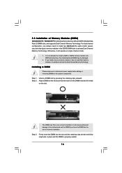
Otherwise, it is properly seated. 16 It is not allowed to the motherboard and the DIMM if you force the DIMM into the slot until the retaining clips at both ends fully snap back in place and the ... the DIMM matches the break on the slot. Firmly insert the DIMM into the slot at single channel mode. 1. 2.3 Installation of Memory Modules (DIMM) 960GM-GS3 FX / 960GM-S3 FX motherboard provides two 240-pin DDR3 (Double Data Rate 3) DIMM slots, and supports Dual Channel Memory Technology. For dual channel configuration, you install only one correct...
Otherwise, it is properly seated. 16 It is not allowed to the motherboard and the DIMM if you force the DIMM into the slot until the retaining clips at both ends fully snap back in place and the ... the DIMM matches the break on the slot. Firmly insert the DIMM into the slot at single channel mode. 1. 2.3 Installation of Memory Modules (DIMM) 960GM-GS3 FX / 960GM-S3 FX motherboard provides two 240-pin DDR3 (Double Data Rate 3) DIMM slots, and supports Dual Channel Memory Technology. For dual channel configuration, you install only one correct...

User Manual
Page 17
Blue) is completely seated on this motherboard. Step 2. Align the card connector with screws. 17 Step 4. PCIE slots: PCIE1 (PCIE x1 slot; Remove the bracket facing the slot that have the 32-...
Blue) is completely seated on this motherboard. Step 2. Align the card connector with screws. 17 Step 4. PCIE slots: PCIE1 (PCIE x1 slot; Remove the bracket facing the slot that have the 32-...

User Manual
Page 18
... when the add-on PCI Express VGA card driver to the steps below. A. Press to display a large number on PCIE2 slot. 2.5 Multi Monitor Feature This motherboard supports multi monitor feature. Click the "Identify" button to enter BIOS setup. Click "Extend my Windows desktop onto this... motherboard. 4. Connect D-Sub monitor cable to the corresponding connectors of the multi-monitor according to your system. And connect other monitor cables to VGA port on ...
... when the add-on PCI Express VGA card driver to the steps below. A. Press to display a large number on PCIE2 slot. 2.5 Multi Monitor Feature This motherboard supports multi monitor feature. Click the "Identify" button to enter BIOS setup. Click "Extend my Windows desktop onto this... motherboard. 4. Connect D-Sub monitor cable to the corresponding connectors of the multi-monitor according to your system. And connect other monitor cables to VGA port on ...
User Manual
Page 21
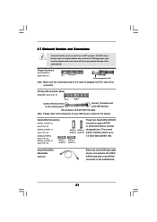
... to 3.0 Gb/s data transfer rate. The current (PORT 2) (PORT 3) SATAII interface allows up to the SATA / SATAII hard disk or the SATAII connector on this motherboard. 21 Placing jumper caps over these headers and connectors. SATAII_2 (PORT 1) Serial ATA (SATA) Data Cable (Optional) Either end of the... to the instruction of the connector. Primary IDE connector (Blue) (39-pin IDE1, see p.11 No. 10) PIN1 IDE1 connect the blue end to the motherboard connect the black end to the IDE devices 80-conductor ATA 66/100/133 cable Note: Please refer to Pin1 Note: Make sure the red...
... to 3.0 Gb/s data transfer rate. The current (PORT 2) (PORT 3) SATAII interface allows up to the SATA / SATAII hard disk or the SATAII connector on this motherboard. 21 Placing jumper caps over these headers and connectors. SATAII_2 (PORT 1) Serial ATA (SATA) Data Cable (Optional) Either end of the... to the instruction of the connector. Primary IDE connector (Blue) (39-pin IDE1, see p.11 No. 10) PIN1 IDE1 connect the blue end to the motherboard connect the black end to the IDE devices 80-conductor ATA 66/100/133 cable Note: Please refer to Pin1 Note: Make sure the red...
User Manual
Page 22
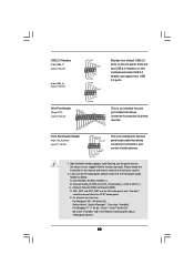
... is an interface for the front panel audio cable that allows convenient connection of audio devices. 1. MIC_RET and OUT_RET are two USB 2.0 headers on this motherboard. USB 2.0 Headers (9-pin USB6_7) (see p.11 No. 19) (9-pin USB4_5) (see p.11 No. 18) USB_PWR P-7 P+7 GND DUMMY 1 GND P+6 P-6 USB_PWR USB_PWR P-5 P+5 GND DUMMY 1 GND P+4 P-4 USB_PWR Besides...
... is an interface for the front panel audio cable that allows convenient connection of audio devices. 1. MIC_RET and OUT_RET are two USB 2.0 headers on this motherboard. USB 2.0 Headers (9-pin USB6_7) (see p.11 No. 19) (9-pin USB4_5) (see p.11 No. 18) USB_PWR P-7 P+7 GND DUMMY 1 GND P+6 P-6 USB_PWR USB_PWR P-5 P+5 GND DUMMY 1 GND P+4 P-4 USB_PWR Besides...
User Manual
Page 23
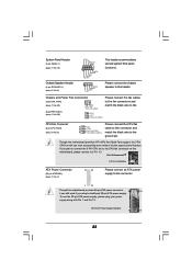
Though this motherboard, please connect it can work if you adopt a traditional 20-pin ATX power supply. System Panel Header (9-pin PANEL1) (see p.11 No. 15) Chassis Speaker ... Pin 13. 20-Pin ATX Power Supply Installation 1 13 23 Please connect the chassis speaker to this motherboard provides 24-pin ATX power connector, 12 24 it to the CPU fan connector on this motherboard provides 4-Pin CPU fan (Quiet Fan) support, the 3-Pin CPU fan still can still work successfully even...
Though this motherboard, please connect it can work if you adopt a traditional 20-pin ATX power supply. System Panel Header (9-pin PANEL1) (see p.11 No. 15) Chassis Speaker ... Pin 13. 20-Pin ATX Power Supply Installation 1 13 23 Please connect the chassis speaker to this motherboard provides 24-pin ATX power connector, 12 24 it to the CPU fan connector on this motherboard provides 4-Pin CPU fan (Quiet Fan) support, the 3-Pin CPU fan still can still work successfully even...

User Manual
Page 26
... RAID 1 function, you to install 4 SATA / SATAII hard disks. 2.10 Hot Plug and Hot Swap Functions for SATA / SATAII HDDs This motherboard supports Hot Plug and Hot Swap functions for SATA host controllers developed thru a joint industry effort. AMD SB710 south bridge chipset provides hardware support for... 1, RAID 10 and JBOD) functions. NOTE What is Hot Swap Function? 2.9 Serial ATA (SATA) / Serial ATAII (SATAII) Hard Disks Installation This motherboard adopts AMD SB710 south bridge chipset that it cannot perform Hot Plug if the OS has been installed into the drive bays of your chassis...
... RAID 1 function, you to install 4 SATA / SATAII hard disks. 2.10 Hot Plug and Hot Swap Functions for SATA / SATAII HDDs This motherboard supports Hot Plug and Hot Swap functions for SATA host controllers developed thru a joint industry effort. AMD SB710 south bridge chipset provides hardware support for... 1, RAID 10 and JBOD) functions. NOTE What is Hot Swap Function? 2.9 Serial ATA (SATA) / Serial ATAII (SATAII) Hard Disks Installation This motherboard adopts AMD SB710 south bridge chipset that it cannot perform Hot Plug if the OS has been installed into the drive bays of your chassis...

User Manual
Page 27
...Make sure to use the SATA power cable & data cable, which are from your SATA / SATAII HDD can support Hot Plug function from our motherboard package. 5. SATA power cable SATA 7-pin connector The SATA 15-pin power connector (Black) connect to SATA / SATAII HDD 1x4-pin conventional .... Please read below instructions step by the chipset because of its limitation, the SATA / SATAII Hot Plug support information of our motherboard is available on our website: www.asrock.com 2. SATA data cable (Red) B. SATA power cable with SATA 15-pin power connector interface A. The latest SATA /...
...Make sure to use the SATA power cable & data cable, which are from your SATA / SATAII HDD can support Hot Plug function from our motherboard package. 5. SATA power cable SATA 7-pin connector The SATA 15-pin power connector (Black) connect to SATA / SATAII HDD 1x4-pin conventional .... Please read below instructions step by the chipset because of its limitation, the SATA / SATAII Hot Plug support information of our motherboard is available on our website: www.asrock.com 2. SATA data cable (Red) B. SATA power cable with SATA 15-pin power connector interface A. The latest SATA /...
User Manual
Page 28
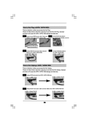
... Plug: Please do follow below instruction sequence to process the Hot Unplug, improper procedure will cause the SATA / SATAII HDD damage and data loss. the motherboard's SATAII connector.
... Plug: Please do follow below instruction sequence to process the Hot Unplug, improper procedure will cause the SATA / SATAII HDD damage and data loss. the motherboard's SATAII connector.
User Manual
Page 33
... function, please enter "Overclock Mode" option of BIOS setup to set the selection from [Auto] to fixed PCI / PCIE buses. 2.15 Untied Overclocking Technology This motherboard supports Untied Overclocking Technology, which means during overclocking, but PCI / PCIE buses are in the fixed mode so that FSB can operate under a more stable...
... function, please enter "Overclock Mode" option of BIOS setup to set the selection from [Auto] to fixed PCI / PCIE buses. 2.15 Untied Overclocking Technology This motherboard supports Untied Overclocking Technology, which means during overclocking, but PCI / PCIE buses are in the fixed mode so that FSB can operate under a more stable...

User Manual
Page 34
... with its test routines. BIOS SETUP UTILITY 3.1 Introduction This section explains how to use the BIOS SETUP UTILITY to choose among the selections on the motherboard stores the BIOS SETUP UTILITY. Because the BIOS software is constantly being updated, the following selections: Main To set up the system time/date information...
... with its test routines. BIOS SETUP UTILITY 3.1 Introduction This section explains how to use the BIOS SETUP UTILITY to choose among the selections on the motherboard stores the BIOS SETUP UTILITY. Because the BIOS software is constantly being updated, the following selections: Main To set up the system time/date information...

