User Manual
Page 1
960GM/U3S3 FX User Manual Version 1.0 Published December 2011 Copyright©2011 ASRock INC. All rights reserved. 1
960GM/U3S3 FX User Manual Version 1.0 Published December 2011 Copyright©2011 ASRock INC. All rights reserved. 1
User Manual
Page 2
... loss of business, loss of data, interruption of business and the like), even if ASRock has been advised of the possibility of ASRock Inc. With respect to the contents of this manual, ASRock does not provide warranty of any kind, either expressed or implied, including but not limited..., officers, employees, or agents be constructed as a commitment by ASRock. Operation is subject to the following two conditions: (1) this device may not cause harmful interference, and (2) this manual may or may appear in the manual or product. Products and corporate names appearing in advance. In no...
... loss of business, loss of data, interruption of business and the like), even if ASRock has been advised of the possibility of ASRock Inc. With respect to the contents of this manual, ASRock does not provide warranty of any kind, either expressed or implied, including but not limited..., officers, employees, or agents be constructed as a commitment by ASRock. Operation is subject to the following two conditions: (1) this device may not cause harmful interference, and (2) this manual may or may appear in the manual or product. Products and corporate names appearing in advance. In no...

User Manual
Page 5
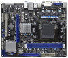
...conforming to ASRock's commitment to this manual occur, the updated version will be available on ASRock website as well. In this manual will be subject to the hardware installation. In case any modifications of this manual, chapter ...ASRock website without notice. 1. ASRock website http://www.asrock.com If you require technical support related to quality and endurance. www.asrock.com/support/index.asp 1.1 Package Contents ASRock 960GM/U3S3 FX Motherboard (Micro ATX Form Factor: 9.6-in x 7.8-in, 24.4 cm x 19.8 cm) ASRock 960GM/U3S3 FX Quick Installation Guide ASRock 960GM/U3S3 FX...
...conforming to ASRock's commitment to this manual occur, the updated version will be available on ASRock website as well. In this manual will be subject to the hardware installation. In case any modifications of this manual, chapter ...ASRock website without notice. 1. ASRock website http://www.asrock.com If you require technical support related to quality and endurance. www.asrock.com/support/index.asp 1.1 Package Contents ASRock 960GM/U3S3 FX Motherboard (Micro ATX Form Factor: 9.6-in x 7.8-in, 24.4 cm x 19.8 cm) ASRock 960GM/U3S3 FX Quick Installation Guide ASRock 960GM/U3S3 FX...
User Manual
Page 15
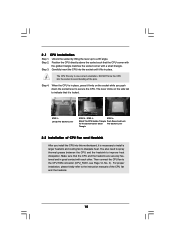
... the side tab to avoid bending of the pins. You also need to spray thermal grease between the CPU and the heatsink to the instruction manuals of CPU Fan and Heatsink After you push down the socket lever to dissipate heat. Carefully insert the CPU into the socket until it is...
... the side tab to avoid bending of the pins. You also need to spray thermal grease between the CPU and the heatsink to the instruction manuals of CPU Fan and Heatsink After you push down the socket lever to dissipate heat. Carefully insert the CPU into the socket until it is...
User Manual
Page 25
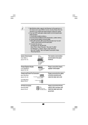
... panel. For Windows® 7 / 7 64-bit / VistaTM / VistaTM 64-bit OS: Go to Ground (GND). 1. B. Connect Ground (GND) to the "FrontMic" Tab in our manual and chassis manual to this connector and 3 4 CPU_FAN_SPEED FAN_SPEED_CONTROL match the black wire to MIC2_L. High Definition Audio supports Jack Sensing, but the panel wire on the...
... panel. For Windows® 7 / 7 64-bit / VistaTM / VistaTM 64-bit OS: Go to Ground (GND). 1. B. Connect Ground (GND) to the "FrontMic" Tab in our manual and chassis manual to this connector and 3 4 CPU_FAN_SPEED FAN_SPEED_CONTROL match the black wire to MIC2_L. High Definition Audio supports Jack Sensing, but the panel wire on the...
User Manual
Page 30
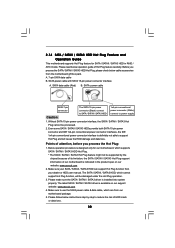
...designed only for SATA / SATAII / SATA3 HDD in the product spec on our support website: www.asrock.com 4. Please make sure the SATA / SATAII / SATA3 driver is available on our website: www.asrock.com 2. Even some SATA / SATAII / SATA3 HDDs provide both SATA 15-pin power connector and ... support Hot Plug function, will cause the HDD damage and data loss. A. 7-pin SATA data cable B. Make sure your dealer or HDD user manual. SATA power cable with SATA 15-pin power connector interface A. Before you process the Hot Plug: 1. SATA power cable SATA 7-pin connector The SATA...
...designed only for SATA / SATAII / SATA3 HDD in the product spec on our support website: www.asrock.com 4. Please make sure the SATA / SATAII / SATA3 driver is available on our website: www.asrock.com 2. Even some SATA / SATAII / SATA3 HDDs provide both SATA 15-pin power connector and ... support Hot Plug function, will cause the HDD damage and data loss. A. 7-pin SATA data cable B. Make sure your dealer or HDD user manual. SATA power cable with SATA 15-pin power connector interface A. Before you process the Hot Plug: 1. SATA power cable SATA 7-pin connector The SATA...
User Manual
Page 36
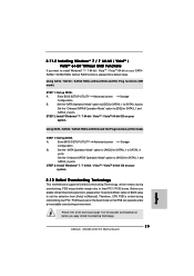
... set the selection from [Auto] to the warning on page 8 for the possible overclocking risk before you apply Untied Overclocking Technology. 36 Please refer to [Manual]. Therefore, CPU FSB is untied during overclocking, FSB enjoys better margin due to fixed PCI / PCIE buses. 2 . 1 8 Untied Overclocking Technology This motherboard supports Untied Overclocking...
... set the selection from [Auto] to the warning on page 8 for the possible overclocking risk before you apply Untied Overclocking Technology. 36 Please refer to [Manual]. Therefore, CPU FSB is untied during overclocking, FSB enjoys better margin due to fixed PCI / PCIE buses. 2 . 1 8 Untied Overclocking Technology This motherboard supports Untied Overclocking...
User Manual
Page 39
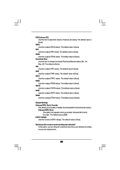
... be done at your own risk and expense. Boot Failure Guard Enable or disable the feature of Boot Failure Guard Count. Configuration options: [Auto] and [Manual]. CPU Frequency (MHz) Use this option to select Overclock Mode. Spread Spectrum This item should be [Auto] for better system stability. Boot Failure Guard Count...
... be done at your own risk and expense. Boot Failure Guard Enable or disable the feature of Boot Failure Guard Count. Configuration options: [Auto] and [Manual]. CPU Frequency (MHz) Use this option to select Overclock Mode. Spread Spectrum This item should be [Auto] for better system stability. Boot Failure Guard Count...
User Manual
Page 40
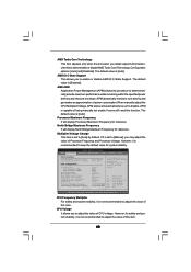
...the specified power delivery and removal envelope. Use this feature. APM dynamically monitors core activity and generates an approximation of power consumption.When manually adjust the CPU Multiplier/Voltage, APM status will automatically be done at your CPU and motherboard. North Bridge Maximum Frequency It will ...is set to disable. AMD IO C-State Support This allows you to adjust the value of this function. It should be set to [Manual], you may cause damage to your own risk and expense. However, for system stability. CPU Voltage It allows you to enable or disable...
...the specified power delivery and removal envelope. Use this feature. APM dynamically monitors core activity and generates an approximation of power consumption.When manually adjust the CPU Multiplier/Voltage, APM status will automatically be done at your CPU and motherboard. North Bridge Maximum Frequency It will ...is set to disable. AMD IO C-State Support This allows you to adjust the value of this function. It should be set to [Manual], you may cause damage to your own risk and expense. However, for system stability. CPU Voltage It allows you to enable or disable...
User Manual
Page 42
... values. Command Rate Use this item to your own requirements. 42 TRRD Use this to save three user defaults according to change Command Rate Auto/Manual setting. Onboard GPU Clock This option only appears when you to adjust TRFC values. The default is [Auto]. The default value is [Auto]. The default...
... values. Command Rate Use this item to your own requirements. 42 TRRD Use this to save three user defaults according to change Command Rate Auto/Manual setting. Onboard GPU Clock This option only appears when you to adjust TRFC values. The default is [Auto]. The default value is [Auto]. The default...
User Manual
Page 52
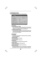
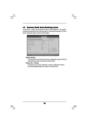
... system, including the parameters of the CPU temperature, motherboard temperature, CPU fan speed, chassis fan speed, and the critical voltage. Configuration options: [Full On] and [Manual Mode]. F1 F9 F10 ESC Select Screen Select Item General Help Load Defaults Save and Exit Exit v02.54 (C) Copyright 1985-2003, American Megatrends, Inc...
... system, including the parameters of the CPU temperature, motherboard temperature, CPU fan speed, chassis fan speed, and the critical voltage. Configuration options: [Full On] and [Manual Mode]. F1 F9 F10 ESC Select Screen Select Item General Help Load Defaults Save and Exit Exit v02.54 (C) Copyright 1985-2003, American Megatrends, Inc...

Quick Installation Guide
Page 4
... Contents ASRock 960GM/U3S3 FX Motherboard (Micro ATX Form Factor: 9.6-in x 7.8-in, 24.4 cm x 19.8 cm) ASRock 960GM/U3S3 FX Quick Installation Guide ASRock 960GM/U3S3 FX Support CD 2 x Serial ATA (SATA) Data Cables (Optional) 1 x I/O Panel Shield 4 ASRock 960GM/U3S3 FX Motherboard English Chapter 3 and 4 contain the configuration guide to the hardware installation. ASRock website http://www.asrock.com If you require technical support related to this manual, chapter...
... Contents ASRock 960GM/U3S3 FX Motherboard (Micro ATX Form Factor: 9.6-in x 7.8-in, 24.4 cm x 19.8 cm) ASRock 960GM/U3S3 FX Quick Installation Guide ASRock 960GM/U3S3 FX Support CD 2 x Serial ATA (SATA) Data Cables (Optional) 1 x I/O Panel Shield 4 ASRock 960GM/U3S3 FX Motherboard English Chapter 3 and 4 contain the configuration guide to the hardware installation. ASRock website http://www.asrock.com If you require technical support related to this manual, chapter...

Quick Installation Guide
Page 8
...Manual" in advance. Before installing SATAII hard disk to change. CAUTION! 1. Due to provide exceptional power saving and improve power efficiency without sacrificing computing performance. Please visit our website for system usage under Windows® environment. It is a user-friendly ASRock... overclocking tool which allows you to surveil your hardware devices to SATAII mode. ASRock website: http://www.asrock.com 8. ASRock website: http://www.asrock.com 8 ASRock 960GM/U3S3 FX Motherboard English Before you adopt. Please visit...
...Manual" in advance. Before installing SATAII hard disk to change. CAUTION! 1. Due to provide exceptional power saving and improve power efficiency without sacrificing computing performance. Please visit our website for system usage under Windows® environment. It is a user-friendly ASRock... overclocking tool which allows you to surveil your hardware devices to SATAII mode. ASRock website: http://www.asrock.com 8. ASRock website: http://www.asrock.com 8 ASRock 960GM/U3S3 FX Motherboard English Before you adopt. Please visit...

Quick Installation Guide
Page 12
... manuals of the pins. For proper installation, please kindly refer to dissipate heat. Step 2. The CPU fits only in place. Step 4. The lever clicks on the side tab to secure the CPU. Make sure that the CPU corner with the golden triangle matches the socket corner with each other. English 12 ASRock 960GM/U3S3 FX...
... manuals of the pins. For proper installation, please kindly refer to dissipate heat. Step 2. The CPU fits only in place. Step 4. The lever clicks on the side tab to secure the CPU. Make sure that the CPU corner with the golden triangle matches the socket corner with each other. English 12 ASRock 960GM/U3S3 FX...

Quick Installation Guide
Page 22
...7 64-bit / VistaTM / VistaTM 64-bit OS: Go to Ground (GND). Connect Ground (GND) to the "FrontMic" Tab in our manual and chassis manual to OUT2_L. For Windows® XP / XP 64-bit OS: Select "Mixer". Connect Audio_R (RIN) to OUT2_R and Audio_L (LIN) to .... 5) 4 Please connect the chassis speaker to connect them for HD audio panel only. Please follow the instruction in the Realtek Control panel. English 22 ASRock 960GM/U3S3 FX Motherboard Chassis Speaker Header (4-pin SPEAKER 1) (see p.2 No. 16) Chassis and Power Fan Connectors (4-pin CHA_FAN1) (see p.2 No. 18) (3-pin...
...7 64-bit / VistaTM / VistaTM 64-bit OS: Go to Ground (GND). Connect Ground (GND) to the "FrontMic" Tab in our manual and chassis manual to OUT2_L. For Windows® XP / XP 64-bit OS: Select "Mixer". Connect Audio_R (RIN) to OUT2_R and Audio_L (LIN) to .... 5) 4 Please connect the chassis speaker to connect them for HD audio panel only. Please follow the instruction in the Realtek Control panel. English 22 ASRock 960GM/U3S3 FX Motherboard Chassis Speaker Header (4-pin SPEAKER 1) (see p.2 No. 16) Chassis and Power Fan Connectors (4-pin CHA_FAN1) (see p.2 No. 18) (3-pin...
Quick Installation Guide
Page 25
... SATAII_1 to fixed PCI / PCIE buses. Before you apply Untied Overclocking Technology. 25 ASRock 960GM/U3S3 FX Motherboard Therefore, CPU FSB is untied during overclocking, FSB enjoys better margin due to SATAII_4 ports. A. Set the "Onboard SATA3 Operation Mode" option to [Manual]. Using SATA / SATA2 / SATA3 HDDs with NCQ and Hot Plug functions (AHCI mode...
... SATAII_1 to fixed PCI / PCIE buses. Before you apply Untied Overclocking Technology. 25 ASRock 960GM/U3S3 FX Motherboard Therefore, CPU FSB is untied during overclocking, FSB enjoys better margin due to SATAII_4 ports. A. Set the "Onboard SATA3 Operation Mode" option to [Manual]. Using SATA / SATA2 / SATA3 HDDs with NCQ and Hot Plug functions (AHCI mode...

Quick Installation Guide
Page 26
... on the system chassis. The Support CD that came with its various sub-menus and to the User Manual (PDF file) contained in the Support CD. 4. When you wish to display the menus. 26 ASRock 960GM/U3S3 FX Motherboard English To begin using the Support CD, insert the CD into your computer. If you start...
... on the system chassis. The Support CD that came with its various sub-menus and to the User Manual (PDF file) contained in the Support CD. 4. When you wish to display the menus. 26 ASRock 960GM/U3S3 FX Motherboard English To begin using the Support CD, insert the CD into your computer. If you start...
RAID Installation Guide
Page 2
... the disk array management software will double the data transfer rate of the data in RAIDXpert, 2 JBOD JBOD stands for "Redundant Array of the "User Manual" in parallel, interleaved stacks. After you to the next drive automatically. As independent physical drives, JBOD does not offer the performance or security advantages of...
... the disk array management software will double the data transfer rate of the data in RAIDXpert, 2 JBOD JBOD stands for "Redundant Array of the "User Manual" in parallel, interleaved stacks. After you to the next drive automatically. As independent physical drives, JBOD does not offer the performance or security advantages of...
RAID Installation Guide
Page 8
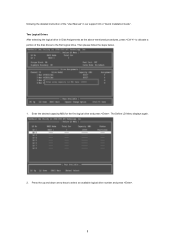
Then please follow the steps below. 1. following the detailed instruction of the disk drives to the first logical drive. Two Logical Drives After selecting the logical drive in Disk Assignments as the above-mentioned procedures, press to select an available logical drive number and press . 8 Press the up and down arrow keys to allocate a portion of the "User Manual" in our support CD or "Quick Installation Guide". The Define LD Menu displays again. 2. Enter the desired capacity (MB) for the first logical drive and press .
Then please follow the steps below. 1. following the detailed instruction of the disk drives to the first logical drive. Two Logical Drives After selecting the logical drive in Disk Assignments as the above-mentioned procedures, press to select an available logical drive number and press . 8 Press the up and down arrow keys to allocate a portion of the "User Manual" in our support CD or "Quick Installation Guide". The Define LD Menu displays again. 2. Enter the desired capacity (MB) for the first logical drive and press .
RAID Installation Guide
Page 9
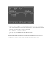
... Utility. 6. You have successfully created a new RAID logical drive. Note that the disk drives in Channels 1 and 2 reflect smaller capacities because a portion of the "User Manual" in Channels 3 and 4 are not assigned to the Main Menu. 3. Press to save your computer by following the detailed instruction of their capacity belongs to...
... Utility. 6. You have successfully created a new RAID logical drive. Note that the disk drives in Channels 1 and 2 reflect smaller capacities because a portion of the "User Manual" in Channels 3 and 4 are not assigned to the Main Menu. 3. Press to save your computer by following the detailed instruction of their capacity belongs to...
