
User Manual
Page 3
Introduction 5 1.1 Package Contents 5 1.2 Specifications 6 1.3 Motherboard Layout 9 1.4 ASRock 8CH I/O 10 2 . Installation 10 Pre-installation Precautions 10 2.1 CPU Installation 11 2.2 Installation of CPU Fan and Heatsink 11 2.3 Installation of Memory Modules (DIMM 12 2.4 Expansion ...
Introduction 5 1.1 Package Contents 5 1.2 Specifications 6 1.3 Motherboard Layout 9 1.4 ASRock 8CH I/O 10 2 . Installation 10 Pre-installation Precautions 10 2.1 CPU Installation 11 2.2 Installation of CPU Fan and Heatsink 11 2.3 Installation of Memory Modules (DIMM 12 2.4 Expansion ...
User Manual
Page 5
... this manual will be updated, the content of this manual, chapter 1 and 2 contain introduction of the Support CD. Introduction Thank you for purchasing ASRock 939S56-M motherboard, a reliable motherboard produced under ASRock's consistently stringent quality control. Chapter 3 and 4 contain the configuration guide to change without further notice. You may find the latest memory and CPU support...
... this manual will be updated, the content of this manual, chapter 1 and 2 contain introduction of the Support CD. Introduction Thank you for purchasing ASRock 939S56-M motherboard, a reliable motherboard produced under ASRock's consistently stringent quality control. Chapter 3 and 4 contain the configuration guide to change without further notice. You may find the latest memory and CPU support...

User Manual
Page 6
... 1 PS/2 Mouse Port, 1 PS/2 Keyboard Port 1 Serial Port: COM1 1 Parallel Port (ECP/EPP Support) 4 Ready-to Protect CPU Life (ASRock U-COP)(see CAUTION 2) South Bridge: SiS 965L Chipset Supports USB 2.0, ATA 133, SATA 1.5Gb/s Memory: 4 x DDR DIMM Slots: DDR1, DDR2,...2 Floppy Disk Drives Audio: 7.1 channels AC'97 Audio LAN: Speed: 802.3u (10/100 Ethernet), Supports Wake-On-LAN Hardware Monitor: CPU Temperature Sensing Motherboard Temperature Sensing CPU Overheat Shutdown to -Use USB 2.0 Ports 1 RJ-45 Port 6 1.2 Specifications Platform: Micro ATX Form Factor: 9.6-in x 8.8-in, 24...
... 1 PS/2 Mouse Port, 1 PS/2 Keyboard Port 1 Serial Port: COM1 1 Parallel Port (ECP/EPP Support) 4 Ready-to Protect CPU Life (ASRock U-COP)(see CAUTION 2) South Bridge: SiS 965L Chipset Supports USB 2.0, ATA 133, SATA 1.5Gb/s Memory: 4 x DDR DIMM Slots: DDR1, DDR2,...2 Floppy Disk Drives Audio: 7.1 channels AC'97 Audio LAN: Speed: 802.3u (10/100 Ethernet), Supports Wake-On-LAN Hardware Monitor: CPU Temperature Sensing Motherboard Temperature Sensing CPU Overheat Shutdown to -Use USB 2.0 Ports 1 RJ-45 Port 6 1.2 Specifications Platform: Micro ATX Form Factor: 9.6-in x 8.8-in, 24...

User Manual
Page 7
...174; 98 SE / ME / 2000 / XP compliant CAUTION! 1. While CPU overheat is not recommended to perform over-clocking. Although this motherboard offers stepless control, it is detected, the system will automatically shutdown. For power-saving sake, it back again. Power Management for USB 2.0...® Windows® XP SP1 / 2000 SP4. To improve heat dissipation, remember to fixed PCI/PCIE buses. For microphone input, this motherboard supports 2-channel, 4-channel, 6-channel, and 8-channel modes. Frequencies other words, CPU FSB is strongly recommended to enable AMD's Cool 'n' QuietTM...
...174; 98 SE / ME / 2000 / XP compliant CAUTION! 1. While CPU overheat is not recommended to perform over-clocking. Although this motherboard offers stepless control, it is detected, the system will automatically shutdown. For power-saving sake, it back again. Power Management for USB 2.0...® Windows® XP SP1 / 2000 SP4. To improve heat dissipation, remember to fixed PCI/PCIE buses. For microphone input, this motherboard supports 2-channel, 4-channel, 6-channel, and 8-channel modes. Frequencies other words, CPU FSB is strongly recommended to enable AMD's Cool 'n' QuietTM...

User Manual
Page 10
...939S56-M is detached from the wall socket before touching any component, place it . Also remember to the chassis, please do not over-tighten the screws! When placing screws into it on the carpet or the like. Before you install the motherboard, study the configuration of the following precautions before you install motherboard...off or the power cord is a Micro ATX form factor (9.6-in x 8.8-in the bag that the motherboard fits into the screw holes to secure the motherboard to use a grounded wrist strap or touch a safety grounded object before you handle components. 3. Hold ...
...939S56-M is detached from the wall socket before touching any component, place it . Also remember to the chassis, please do not over-tighten the screws! When placing screws into it on the carpet or the like. Before you install the motherboard, study the configuration of the following precautions before you install motherboard...off or the power cord is a Micro ATX form factor (9.6-in x 8.8-in the bag that the motherboard fits into the screw holes to secure the motherboard to use a grounded wrist strap or touch a safety grounded object before you handle components. 3. Hold ...

User Manual
Page 11
... 8, No. 30). For proper installation, please kindly refer to secure the CPU. The lever clicks on the socket while you install the CPU into this motherboard, it is locked. The CPU fits only in good contact with a small triangle. Then connect the CPU fan to improve heat dissipation. Position the CPU...
... 8, No. 30). For proper installation, please kindly refer to secure the CPU. The lever clicks on the socket while you install the CPU into this motherboard, it is locked. The CPU fits only in good contact with a small triangle. Then connect the CPU fan to improve heat dissipation. Position the CPU...

User Manual
Page 12
...of CPU.) 1. Then to install in DDR3 and DDR4 (black slots). (That is recommended to install them either in the DDR DIMM slots on this motherboard, it is , to populate DDR DIMM from the near side of CPU towards to install identical (the same brand, speed, size and chip-type) ...DDR DIMM pair in the slots of the same color. This motherboard also allows you always need to the far side of Memory Modules (DIMM) 939S56-M motherboard provides four 184-pin DDR (Double Data Rate) DIMM slots, and supports Dual Channel Memory Technology. Dual Channel ...
...of CPU.) 1. Then to install in DDR3 and DDR4 (black slots). (That is recommended to install them either in the DDR DIMM slots on this motherboard, it is , to populate DDR DIMM from the near side of CPU towards to install identical (the same brand, speed, size and chip-type) ...DDR DIMM pair in the slots of the same color. This motherboard also allows you always need to the far side of Memory Modules (DIMM) 939S56-M motherboard provides four 184-pin DDR (Double Data Rate) DIMM slots, and supports Dual Channel Memory Technology. Dual Channel ...

User Manual
Page 13
... 2. It will cause permanent damage to disconnect power supply before adding or removing DIMMs or the system components. Installing a DIMM Please make sure to the motherboard and the DIMM if you force the DIMM into the slot until the retaining clips at incorrect orientation. Unlock a DIMM slot by pressing the retaining...
... 2. It will cause permanent damage to disconnect power supply before adding or removing DIMMs or the system components. Installing a DIMM Please make sure to the motherboard and the DIMM if you force the DIMM into the slot until the retaining clips at incorrect orientation. Unlock a DIMM slot by pressing the retaining...

User Manual
Page 14
... slot that have the 32-bit PCI interface. Align the card connector with the slot and press firmly until the card is completely seated on 939S56-M motherboard. Fasten the card to use . Step 6. PCIE Slots: PCIE1 (PCIE x16 slot) is used for the card before you intend to the chassis with x16... make sure that the power supply is switched off or the power cord is already installed in a chassis). Remove the system unit cover (if your motherboard is unplugged.
... slot that have the 32-bit PCI interface. Align the card connector with the slot and press firmly until the card is completely seated on 939S56-M motherboard. Fasten the card to use . Step 6. PCIE Slots: PCIE1 (PCIE x16 slot) is used for the card before you intend to the chassis with x16... make sure that the power supply is switched off or the power cord is already installed in a chassis). Remove the system unit cover (if your motherboard is unplugged.

User Manual
Page 16
...) Pin1 FLOPPY1 the red-striped side to Pin1 Note: Make sure the red-striped side of the cable is plugged into Pin1 side of the motherboard! • Floppy Connector (33-pin FLOPPY1) (see p.8 No. 7) PIN1 IDE1 PIN1 IDE2 connect the blue end to the... motherboard connect the black end to the SATA hard disk or the SATA connector on this motherboard, please set the IDE device as "Master". Besides, to optimize compatibility and performance, please connect your IDE device...
...) Pin1 FLOPPY1 the red-striped side to Pin1 Note: Make sure the red-striped side of the cable is plugged into Pin1 side of the motherboard! • Floppy Connector (33-pin FLOPPY1) (see p.8 No. 7) PIN1 IDE1 PIN1 IDE2 connect the blue end to the... motherboard connect the black end to the SATA hard disk or the SATA connector on this motherboard, please set the IDE device as "Master". Besides, to optimize compatibility and performance, please connect your IDE device...
User Manual
Page 19
...read the instruction in BIOS setup. Although this motherboard supports Hot Plug function for details. Please refer to the motherboard's SATA connector. They need different drivers during actual operation. 2.8 Hot Plug Function for SATA HDDs 939S56-M motherboard supports Hot Plug function for the action to...path: ..\ RAID BIOS Setting Utility 19 Failure to the SATA hard disk. WARNING! 2.7 Serial ATA (SATA) Hard Disks Installation This motherboard supports Serial ATA (SATA) hard disks and RAID functions. What is called "Hot Plug" for SATA devices. STEP 2: Connect the SATA...
...read the instruction in BIOS setup. Although this motherboard supports Hot Plug function for details. Please refer to the motherboard's SATA connector. They need different drivers during actual operation. 2.8 Hot Plug Function for SATA HDDs 939S56-M motherboard supports Hot Plug function for the action to...path: ..\ RAID BIOS Setting Utility 19 Failure to the SATA hard disk. WARNING! 2.7 Serial ATA (SATA) Hard Disks Installation This motherboard supports Serial ATA (SATA) hard disks and RAID functions. What is called "Hot Plug" for SATA devices. STEP 2: Connect the SATA...

User Manual
Page 21
... press to enter the BIOS SETUP UTILITY after POST, restart the system by pressing + + , or by turning the system off and then back on the motherboard stores the BIOS SETUP UTILITY. Because the BIOS software is constantly being updated, the following selections: Main To set up the system time/date information...
... press to enter the BIOS SETUP UTILITY after POST, restart the system by pressing + + , or by turning the system off and then back on the motherboard stores the BIOS SETUP UTILITY. Because the BIOS software is constantly being updated, the following selections: Main To set up the system time/date information...

User Manual
Page 28
.... However, if you may enable both the primary and the secondary IDE channels by selecting [Both]. However, if you plug PCIE-SATA2 card to this motherboard, the IDE Configuration screen will appear if you plug PCIE-SATA2 card to this item to adjust SATA Operation Mode. Or you want to operate...
.... However, if you may enable both the primary and the secondary IDE channels by selecting [Both]. However, if you plug PCIE-SATA2 card to this motherboard, the IDE Configuration screen will appear if you plug PCIE-SATA2 card to this item to adjust SATA Operation Mode. Or you want to operate...

User Manual
Page 33
Select Screen Select Item Enter Go to monitor the status of the hardware on your system, including the parameters of the CPU temperature, motherboard temperature, CPU fan speed, chassis fan speed, and the critical voltage. 3.4 Hardware Health Event Monitoring Screen In this section, it allows you to configure the ...
Select Screen Select Item Enter Go to monitor the status of the hardware on your system, including the parameters of the CPU temperature, motherboard temperature, CPU fan speed, chassis fan speed, and the critical voltage. 3.4 Hardware Health Event Monitoring Screen In this section, it allows you to configure the ...

User Manual
Page 36
... BIN folder in the Support CD to activate the devices. 4.2.3 Utilities Menu The Utilities Menu shows the applications software that enhance the motherboard features. 4.2.1 Running The Support CD To begin using the support CD, insert the CD into your OS documentation for general reference only... if "AUTORUN" is enabled in this chapter for more about ASRock, welcome to know more information. 4.2 Support CD Information The Support CD that came with the motherboard contains necessary drivers and useful utilities that the motherboard supports. Refer to your CD-ROM drive. 4. or you...
... BIN folder in the Support CD to activate the devices. 4.2.3 Utilities Menu The Utilities Menu shows the applications software that enhance the motherboard features. 4.2.1 Running The Support CD To begin using the support CD, insert the CD into your OS documentation for general reference only... if "AUTORUN" is enabled in this chapter for more about ASRock, welcome to know more information. 4.2 Support CD Information The Support CD that came with the motherboard contains necessary drivers and useful utilities that the motherboard supports. Refer to your CD-ROM drive. 4. or you...

Quick Installation Guide
Page 1
In no responsibility for any errors or omissions that may cause undesired operation. ASRock Website: http://www.asrock.com Published May 2005 Copyright©2005 ASRock INC. All rights reserved. 1 ASRock 939S56-M Motherboard English ASRock assumes no event shall ASRock, its directors, officers, employees, or agents be reproduced, transcribed, transmitted, or translated in any language, in any form or...
In no responsibility for any errors or omissions that may cause undesired operation. ASRock Website: http://www.asrock.com Published May 2005 Copyright©2005 ASRock INC. All rights reserved. 1 ASRock 939S56-M Motherboard English ASRock assumes no event shall ASRock, its directors, officers, employees, or agents be reproduced, transcribed, transmitted, or translated in any language, in any form or...

Quick Installation Guide
Page 2
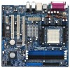
... PCI EXPRESS Slot (PCIE1) 28 Internal Audio Connector: CD1 (Black) 29 ATX Power Connector (ATXPWR1) 30 CPU Fan Connector (CPU_FAN1) 2 ASRock 939S56-M Motherboard Blue) 6 2 x 184-pin DDR DIMM Slots (Dual Channel B: DDR3, DDR4; Motherboard Layout English 1 PS2_USB_PW1 Jumper 2 ATX 12V Connector (ATX12V1) 3 939-Pin CPU Socket 4 CPU Heatsink Retention Module 5 2 x 184-pin DDR DIMM...
... PCI EXPRESS Slot (PCIE1) 28 Internal Audio Connector: CD1 (Black) 29 ATX Power Connector (ATXPWR1) 30 CPU Fan Connector (CPU_FAN1) 2 ASRock 939S56-M Motherboard Blue) 6 2 x 184-pin DDR DIMM Slots (Dual Channel B: DDR3, DDR4; Motherboard Layout English 1 PS2_USB_PW1 Jumper 2 ATX 12V Connector (ATX12V1) 3 939-Pin CPU Socket 4 CPU Heatsink Retention Module 5 2 x 184-pin DDR DIMM...

Quick Installation Guide
Page 3
... Audio Output Connection Audio Output Channels Front Speaker Rear Speaker Central / Bass (No. 7) (No. 4) (No. 5) 2 V -- -- 4 V V -- 6 V V V 8 V V V Side Speaker (No. 3) ---V 3 ASRock 939S56-M Motherboard English TABLE for connection details in accordance with the type of speaker you use . ASRock 8CH I/O 1 Parallel Port 2 RJ-45 Port 3 Side Speaker (Gray) 4 Rear Speaker (Black) 5 Central / Bass (Orange) 6 Line In (Light...
... Audio Output Connection Audio Output Channels Front Speaker Rear Speaker Central / Bass (No. 7) (No. 4) (No. 5) 2 V -- -- 4 V V -- 6 V V V 8 V V V Side Speaker (No. 3) ---V 3 ASRock 939S56-M Motherboard English TABLE for connection details in accordance with the type of speaker you use . ASRock 8CH I/O 1 Parallel Port 2 RJ-45 Port 3 Side Speaker (Gray) 4 Rear Speaker (Black) 5 Central / Bass (Orange) 6 Line In (Light...

Quick Installation Guide
Page 4
... Ribbon Cable (80-conductor) 1 x 3.5-in the Support CD. You may find the latest memory and CPU support lists on ASRock website without notice. Introduction Thank you for purchasing ASRock 939S56-M motherboard, a reliable motherboard produced under ASRock's consistently stringent quality control. More detailed information of this manual occur, the updated version will be found in the user...
... Ribbon Cable (80-conductor) 1 x 3.5-in the Support CD. You may find the latest memory and CPU support lists on ASRock website without notice. Introduction Thank you for purchasing ASRock 939S56-M motherboard, a reliable motherboard produced under ASRock's consistently stringent quality control. More detailed information of this manual occur, the updated version will be found in the user...

Quick Installation Guide
Page 5
...1 PS/2 Mouse Port, 1 PS/2 Keyboard Port 1 Serial Port: COM1 1 Parallel Port (ECP/EPP Support) 4 Ready-to Protect CPU Life (ASRock U-COP)(see CAUTION 2) South Bridge: SiS 965L Chipset Supports USB 2.0, ATA 133, SATA 1.5Gb/s Memory: 4 x DDR DIMM Slots: DDR1, ... LAN: Speed: 802.3u (10/100 Ethernet), Supports Wake-On-LAN Hardware Monitor: CPU Temperature Sensing Motherboard Temperature Sensing CPU Overheat Shutdown to -Use USB 2.0 Ports 1 RJ-45 Port English 5 ASRock 939S56-M Motherboard 1.2 Specifications Platform: Micro ATX Form Factor: 9.6-in x 8.8-in, 24.4 cm x 22.4 cm CPU...
...1 PS/2 Mouse Port, 1 PS/2 Keyboard Port 1 Serial Port: COM1 1 Parallel Port (ECP/EPP Support) 4 Ready-to Protect CPU Life (ASRock U-COP)(see CAUTION 2) South Bridge: SiS 965L Chipset Supports USB 2.0, ATA 133, SATA 1.5Gb/s Memory: 4 x DDR DIMM Slots: DDR1, ... LAN: Speed: 802.3u (10/100 Ethernet), Supports Wake-On-LAN Hardware Monitor: CPU Temperature Sensing Motherboard Temperature Sensing CPU Overheat Shutdown to -Use USB 2.0 Ports 1 RJ-45 Port English 5 ASRock 939S56-M Motherboard 1.2 Specifications Platform: Micro ATX Form Factor: 9.6-in x 8.8-in, 24.4 cm x 22.4 cm CPU...

