
User Manual
Page 6
1.2 Specifications Platform: Micro ATX Form Factor: 9.6-in x 8.8-in, 24.4 cm x 22.4 cm CPU: 939-Pin Socket Supporting AMD AthlonTM 64 / 64FX / 64 X2 Processors Supports AMD's Cool 'n' QuietTM Technology (see CAUTION 1) Chipsets: North Bridge: SiS 756 Chipset FSB @ 1 GHz (2.0 ... Specification 1.0a USB 2.0: 8 USB 2.0 Ports: 4 Ready-to-Use USB 2.0 Ports on the I/O Panel Plus 2 On-Board Headers Supporting 4 Extra USB 2.0 Ports (see CAUTION 4) ASRock 8CH I/O: 1 PS/2 Mouse Port, 1 PS/2 Keyboard Port 1 Serial Port: COM1 1 Parallel Port (ECP/EPP Support) 4 Ready-to Protect CPU Life...
1.2 Specifications Platform: Micro ATX Form Factor: 9.6-in x 8.8-in, 24.4 cm x 22.4 cm CPU: 939-Pin Socket Supporting AMD AthlonTM 64 / 64FX / 64 X2 Processors Supports AMD's Cool 'n' QuietTM Technology (see CAUTION 1) Chipsets: North Bridge: SiS 756 Chipset FSB @ 1 GHz (2.0 ... Specification 1.0a USB 2.0: 8 USB 2.0 Ports: 4 Ready-to-Use USB 2.0 Ports on the I/O Panel Plus 2 On-Board Headers Supporting 4 Extra USB 2.0 Ports (see CAUTION 4) ASRock 8CH I/O: 1 PS/2 Mouse Port, 1 PS/2 Keyboard Port 1 Serial Port: COM1 1 Parallel Port (ECP/EPP Support) 4 Ready-to Protect CPU Life...

User Manual
Page 10
... your chassis to the motherboard, peripherals, and/or components. 1. Whenever you handle components. 3. 2. Also remember to do not touch the ICs. 4. Installation 939S56-M is detached from the wall socket before you install the motherboard, study the configuration of the following precautions before touching any component, place it . When placing screws into it...
... your chassis to the motherboard, peripherals, and/or components. 1. Whenever you handle components. 3. 2. Also remember to do not touch the ICs. 4. Installation 939S56-M is detached from the wall socket before you install the motherboard, study the configuration of the following precautions before touching any component, place it . When placing screws into it...

User Manual
Page 11
...is in good contact with a small triangle. Then connect the CPU fan to the instruction manuals of the pins. Carefully insert the CPU into the socket to dissipate heat. For proper installation, please kindly refer to the CPU FAN connector (CPU_FAN1, see Page 8, No. 30). Position the CPU ... the CPU into this motherboard, it fits in one correct orientation. Step 3. Step 4. Step 2. The CPU fits only in place. Unlock the socket by lifting the lever up to improve heat dissipation. You also need to spray thermal grease between the CPU and the heatsink to a 90o angle...
...is in good contact with a small triangle. Then connect the CPU fan to the instruction manuals of the pins. Carefully insert the CPU into the socket to dissipate heat. For proper installation, please kindly refer to the CPU FAN connector (CPU_FAN1, see Page 8, No. 30). Position the CPU ... the CPU into this motherboard, it fits in one correct orientation. Step 3. Step 4. Step 2. The CPU fits only in place. Unlock the socket by lifting the lever up to improve heat dissipation. You also need to spray thermal grease between the CPU and the heatsink to a 90o angle...

Quick Installation Guide
Page 2
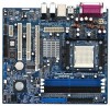
Motherboard Layout English 1 PS2_USB_PW1 Jumper 2 ATX 12V Connector (ATX12V1) 3 939-Pin CPU Socket 4 CPU Heatsink Retention Module 5 2 x 184-pin DDR DIMM Slots (Dual Channel A: DDR1, DDR2; Black) 7 Secondary IDE Connector (IDE2, Black) 8 Primary IDE Connector (IDE1, Blue) 9 North ...) 26 PCI Slots (PCI1 - 2) 27 PCI EXPRESS Slot (PCIE1) 28 Internal Audio Connector: CD1 (Black) 29 ATX Power Connector (ATXPWR1) 30 CPU Fan Connector (CPU_FAN1) 2 ASRock 939S56-M Motherboard Blue) 6 2 x 184-pin DDR DIMM Slots (Dual Channel B: DDR3, DDR4;
Motherboard Layout English 1 PS2_USB_PW1 Jumper 2 ATX 12V Connector (ATX12V1) 3 939-Pin CPU Socket 4 CPU Heatsink Retention Module 5 2 x 184-pin DDR DIMM Slots (Dual Channel A: DDR1, DDR2; Black) 7 Secondary IDE Connector (IDE2, Black) 8 Primary IDE Connector (IDE1, Blue) 9 North ...) 26 PCI Slots (PCI1 - 2) 27 PCI EXPRESS Slot (PCIE1) 28 Internal Audio Connector: CD1 (Black) 29 ATX Power Connector (ATXPWR1) 30 CPU Fan Connector (CPU_FAN1) 2 ASRock 939S56-M Motherboard Blue) 6 2 x 184-pin DDR DIMM Slots (Dual Channel B: DDR3, DDR4;

Quick Installation Guide
Page 5
... Specifications Platform: Micro ATX Form Factor: 9.6-in x 8.8-in, 24.4 cm x 22.4 cm CPU: 939-Pin Socket Supporting AMD AthlonTM 64 / 64FX / 64 X2 Processors Supports AMD's Cool 'n' QuietTM Technology (see CAUTION 1) Chipsets: ...-to-Use USB 2.0 Ports on the I/O Panel Plus 2 On-Board Headers Supporting 4 Extra USB 2.0 Ports (see CAUTION 4) ASRock 8CH I/O: 1 PS/2 Mouse Port, 1 PS/2 Keyboard Port 1 Serial Port: COM1 1 Parallel Port (ECP/EPP Support) 4 Ready-to Protect CPU Life... Sensing CPU Overheat Shutdown to -Use USB 2.0 Ports 1 RJ-45 Port English 5 ASRock 939S56-M Motherboard
... Specifications Platform: Micro ATX Form Factor: 9.6-in x 8.8-in, 24.4 cm x 22.4 cm CPU: 939-Pin Socket Supporting AMD AthlonTM 64 / 64FX / 64 X2 Processors Supports AMD's Cool 'n' QuietTM Technology (see CAUTION 1) Chipsets: ...-to-Use USB 2.0 Ports on the I/O Panel Plus 2 On-Board Headers Supporting 4 Extra USB 2.0 Ports (see CAUTION 4) ASRock 8CH I/O: 1 PS/2 Mouse Port, 1 PS/2 Keyboard Port 1 Serial Port: COM1 1 Parallel Port (ECP/EPP Support) 4 Ready-to Protect CPU Life... Sensing CPU Overheat Shutdown to -Use USB 2.0 Ports 1 RJ-45 Port English 5 ASRock 939S56-M Motherboard

Quick Installation Guide
Page 7
...to the instruction manuals of the pins. Position the CPU directly above the socket such that comes with the component. 5. The lever clicks on the socket while you push down the socket lever to use a grounded wrist strap or touch a safety grounded object ... 2. Installation Pre-installation Precautions Take note of the socket lever. When the CPU is locked. To avoid damaging the motherboard components due to static electricity, NEVER place your CPU fan and heatsink vendors. Step 4. English 7 ASRock 939S56-M Motherboard Install CPU fan and heatsink. Whenever you ...
...to the instruction manuals of the pins. Position the CPU directly above the socket such that comes with the component. 5. The lever clicks on the socket while you push down the socket lever to use a grounded wrist strap or touch a safety grounded object ... 2. Installation Pre-installation Precautions Take note of the socket lever. When the CPU is locked. To avoid damaging the motherboard components due to static electricity, NEVER place your CPU fan and heatsink vendors. Step 4. English 7 ASRock 939S56-M Motherboard Install CPU fan and heatsink. Whenever you ...