
User Manual
Page 3
Installation 12 Pre-installation Precautions 12 2.1 CPU Installation 13 2.2 Installation of CPU Fan and Heatsink 13 2.3 Installation of Memory Modules (DIMM 14 2.4 Expansion Slots (PCI and PCI Express Slots 16 2.5 Dual Monitor ... ATAII (SATAII) Hard Disks Installation 27 2.11 Hot Plug and Hot Swap Functions for Windows® VistaTM Premium 2007 and Basic Logo 9 1.4 Motherboard Layout 10 1.5 ASRock DVI/H I/O 11 2 . Contents 1 . Introduction 5 1.1 Package Contents 5 1.2 Specifications 6 1.3 Minimum Hardware Requirement Table for SATA / SATAII HDDs ....... 27 2.12 SATA / SATAII ...
Installation 12 Pre-installation Precautions 12 2.1 CPU Installation 13 2.2 Installation of CPU Fan and Heatsink 13 2.3 Installation of Memory Modules (DIMM 14 2.4 Expansion Slots (PCI and PCI Express Slots 16 2.5 Dual Monitor ... ATAII (SATAII) Hard Disks Installation 27 2.11 Hot Plug and Hot Swap Functions for Windows® VistaTM Premium 2007 and Basic Logo 9 1.4 Motherboard Layout 10 1.5 ASRock DVI/H I/O 11 2 . Contents 1 . Introduction 5 1.1 Package Contents 5 1.2 Specifications 6 1.3 Minimum Hardware Requirement Table for SATA / SATAII HDDs ....... 27 2.12 SATA / SATAII ...

User Manual
Page 4
BIOS SETUP UTILITY 35 3.1 Introduction 35 3.1.1 BIOS Menu Bar 35 3.1.2 Navigation Keys 36 3.2 Main Screen 36 3.3 Advanced Screen 37 3.3.1 CPU Configuration 37 3.3.2 Chipset Configuration 40 3.3.3 ACPI Configuration 42 3.3.4 IDE Configuration 43 3.3.5 PCIPnP Configuration 45 3.3.6 Floppy Configuration 46 3.3.7 Super IO Configuration 46 3.3.8 USB Configuration 47 3.4 Hardware ...
BIOS SETUP UTILITY 35 3.1 Introduction 35 3.1.1 BIOS Menu Bar 35 3.1.2 Navigation Keys 36 3.2 Main Screen 36 3.3 Advanced Screen 37 3.3.1 CPU Configuration 37 3.3.2 Chipset Configuration 40 3.3.3 ACPI Configuration 42 3.3.4 IDE Configuration 43 3.3.5 PCIPnP Configuration 45 3.3.6 Floppy Configuration 46 3.3.7 Super IO Configuration 46 3.3.8 USB Configuration 47 3.4 Hardware ...

User Manual
Page 5
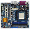
... notice. You may find the latest VGA cards and CPU support lists on ASRock website without notice. In case any modifications of this ...ASRock 939N68PV-GLAN motherboard, a reliable motherboard produced under ASRock's consistently stringent quality control. ASRock website http://www.asrock.com If you require technical support related to the hardware installation. 1. www.asrock.com/support/index.asp 1.1 Package Contents 1 x ASRock 939N68PV-GLAN Motherboard (Micro ATX Form Factor: 9.6-in x 8.6-in, 24.4 cm x 21.8 cm) 1 x ASRock 939N68PV-GLAN Quick Installation Guide 2 x ASRock 939N68PV-GLAN...
... notice. You may find the latest VGA cards and CPU support lists on ASRock website without notice. In case any modifications of this ...ASRock 939N68PV-GLAN motherboard, a reliable motherboard produced under ASRock's consistently stringent quality control. ASRock website http://www.asrock.com If you require technical support related to the hardware installation. 1. www.asrock.com/support/index.asp 1.1 Package Contents 1 x ASRock 939N68PV-GLAN Motherboard (Micro ATX Form Factor: 9.6-in x 8.6-in, 24.4 cm x 21.8 cm) 1 x ASRock 939N68PV-GLAN Quick Installation Guide 2 x ASRock 939N68PV-GLAN...

User Manual
Page 6
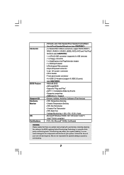
... Overclocking Technology (see CAUTION 4) - Max. shared memory 256MB - Dual VGA Output: support DVI-D and D-Sub ports by independent display controllers - CPU Frequency Stepless Control (see CAUTION 1) - Integrated NVIDIA® GeForce7 Series (NV44) - ASRock U-COP (see CAUTION 3) - NVIDIA® PureVideoTM Ready - 7.1 CH Windows® VistaTM Premium Level HD Audio (ALC888 Audio Codec) - 1.2 Specifications...
... Overclocking Technology (see CAUTION 4) - Max. shared memory 256MB - Dual VGA Output: support DVI-D and D-Sub ports by independent display controllers - CPU Frequency Stepless Control (see CAUTION 1) - Integrated NVIDIA® GeForce7 Series (NV44) - ASRock U-COP (see CAUTION 3) - NVIDIA® PureVideoTM Ready - 7.1 CH Windows® VistaTM Premium Level HD Audio (ALC888 Audio Codec) - 1.2 Specifications...
User Manual
Page 7
...IDE connector (supports 2 x IDE devices) - 1 x Floppy connector - 1 x DeskExpress Hot Plug Detection header - 1 x COM port header - CPU Fan Tachometer - CPU Quiet Fan - CPU/Chassis FAN connector - 24 pin ATX power connector - 4 pin 12V power connector - Supports "Plug and Play" - Microsoft® Windows® 2000...functions (see CAUTION 9) - 4Mb AMI BIOS - SMBIOS 2.3.1 Support - Voltage Monitoring: +12V, +5V, +3.3V, Vcore - CPU Temperature Sensing - Connector BIOS Feature Support CD Hardware Monitor OS Certifications - Chassis Fan Tachometer - FCC, CE, Microsoft® WHQL...
...IDE connector (supports 2 x IDE devices) - 1 x Floppy connector - 1 x DeskExpress Hot Plug Detection header - 1 x COM port header - CPU Fan Tachometer - CPU Quiet Fan - CPU/Chassis FAN connector - 24 pin ATX power connector - 4 pin 12V power connector - Supports "Plug and Play" - Microsoft® Windows® 2000...functions (see CAUTION 9) - 4Mb AMI BIOS - SMBIOS 2.3.1 Support - Voltage Monitoring: +12V, +5V, +3.3V, Vcore - CPU Temperature Sensing - Connector BIOS Feature Support CD Hardware Monitor OS Certifications - Chassis Fan Tachometer - FCC, CE, Microsoft® WHQL...
User Manual
Page 8
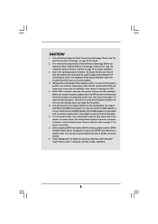
... For Windows® XP 64-bit and Windows® VistaTM 64bit with our product, please refer to HDMI adapter is not bundled with 64-bit CPU, there is no such limitation. 4. Frequencies other than 4GB for the reservation for details. 2. DVI to the adapter vendor for USB 2.0 works fine...this motherboard offers stepless control, it back again. To improve heat dissipation, remember to read the installation guide of the system or damage the CPU. 5. Please check the table on page 11 for the chipset adopted on the motherboard functions properly and unplug the power cord, then plug...
... For Windows® XP 64-bit and Windows® VistaTM 64bit with our product, please refer to HDMI adapter is not bundled with 64-bit CPU, there is no such limitation. 4. Frequencies other than 4GB for the reservation for details. 2. DVI to the adapter vendor for USB 2.0 works fine...this motherboard offers stepless control, it back again. To improve heat dissipation, remember to read the installation guide of the system or damage the CPU. 5. Please check the table on page 11 for the chipset adopted on the motherboard functions properly and unplug the power cord, then plug...

User Manual
Page 9
CPU Memory VGA Athlon 3000+ 512MB DDR400 x 2 Dual Channel (Premium) 512MB Single Channel (Basic) 256MB x 2 Dual Channel (Basic) DX9.0 with WDDM Driver DVI with total system ...® VistaTM Premium 2007 and Basic Logo For system integrators and users who purchase this motherboard, please refer to Premium Discrete requirement at http://www.asrock.com * If the onboard VGA supports DVI, it must also support HDCP function to qualify for Windows® VistaTM Premium 2007 logo. * After June 1, 2007...
CPU Memory VGA Athlon 3000+ 512MB DDR400 x 2 Dual Channel (Premium) 512MB Single Channel (Basic) 256MB x 2 Dual Channel (Basic) DX9.0 with WDDM Driver DVI with total system ...® VistaTM Premium 2007 and Basic Logo For system integrators and users who purchase this motherboard, please refer to Premium Discrete requirement at http://www.asrock.com * If the onboard VGA supports DVI, it must also support HDCP function to qualify for Windows® VistaTM Premium 2007 logo. * After June 1, 2007...

User Manual
Page 13
... manuals of the pins. Step 4. For proper installation, please kindly refer to secure the CPU. 2.1 CPU Installation Step 1. Step 3. You also need to spray thermal grease between the CPU and the heatsink to the CPU FAN connector (CPU_FAN1, see Page 10, No. 6). Unlock the socket by lifting the ...lever up to indicate that the CPU corner with the golden triangle matches the socket corner with each other. Position the CPU directly above the socket such that it is locked. The lever clicks on the socket while you...
... manuals of the pins. Step 4. For proper installation, please kindly refer to secure the CPU. 2.1 CPU Installation Step 1. Step 3. You also need to spray thermal grease between the CPU and the heatsink to the CPU FAN connector (CPU_FAN1, see Page 10, No. 6). Unlock the socket by lifting the ...lever up to indicate that the CPU corner with the golden triangle matches the socket corner with each other. Position the CPU directly above the socket such that it is locked. The lever clicks on the socket while you...
User Manual
Page 24
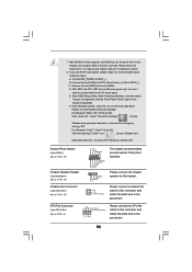
.... 19) Chassis Fan Connector (3-pin CHA_FAN1) (see p.10 No. 6) +12V CPU_FAN_SPEED GND FAN_SPEED_CONTROL 1 2 3 4 Please connect the CPU fan cable to this connector and match the black wire to the front panel audio header as below: A. CPU Fan Connector (4-pin CPU_FAN1) (see p.10 No. 12) PLED+ PLEDPWRBTN# GND 1 DUMMY RESET# GND HDLEDHDLED+ 1 SPEAKER...
.... 19) Chassis Fan Connector (3-pin CHA_FAN1) (see p.10 No. 6) +12V CPU_FAN_SPEED GND FAN_SPEED_CONTROL 1 2 3 4 Please connect the CPU fan cable to this connector and match the black wire to the front panel audio header as below: A. CPU Fan Connector (4-pin CPU_FAN1) (see p.10 No. 12) PLED+ PLEDPWRBTN# GND 1 DUMMY RESET# GND HDLEDHDLED+ 1 SPEAKER...

User Manual
Page 25
... connector. Though this motherboard, please connect it can still work if you plan to connect the 3-Pin CPU fan to the CPU fan connector on this motherboard provides 4-Pin CPU fan (Quiet Fan) support, the 3-Pin CPU fan still can work successfully even without the fan speed control function. To use the 20-pin...
... connector. Though this motherboard, please connect it can still work if you plan to connect the 3-Pin CPU fan to the CPU fan connector on this motherboard provides 4-Pin CPU fan (Quiet Fan) support, the 3-Pin CPU fan still can work successfully even without the fan speed control function. To use the 20-pin...
User Manual
Page 34
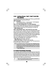
... part of BIOS setup to set RAID configuration. NVIDIA® RAID drivers are in the following path in BIOS first. Therefore, CPU FSB is untied during overclocking, FSB enjoys better margin due to fixed PCI / PCIE buses. Please refer to the warning on ... RAID Installation Guide 2 . 1 6 Untied Overclocking Technology This motherboard supports Untied Overclocking Technology, which means during overclocking, but PCI / PCIE buses are two ASRock Support CD in the Support CD: .. \ RAID Installation Guide STEP 3: Install Windows® VistaTM / VistaTM 64-bit OS on your SATA / SATAII ...
... part of BIOS setup to set RAID configuration. NVIDIA® RAID drivers are in the following path in BIOS first. Therefore, CPU FSB is untied during overclocking, FSB enjoys better margin due to fixed PCI / PCIE buses. Please refer to the warning on ... RAID Installation Guide 2 . 1 6 Untied Overclocking Technology This motherboard supports Untied Overclocking Technology, which means during overclocking, but PCI / PCIE buses are two ASRock Support CD in the Support CD: .. \ RAID Installation Guide STEP 3: Install Windows® VistaTM / VistaTM 64-bit OS on your SATA / SATAII ...
User Manual
Page 37
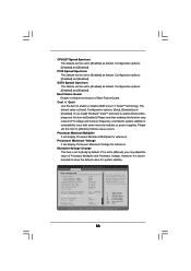
...400 V [Auto] [Auto] [Disabled] [Auto] [Auto] [Auto] If AUTO, multiplier and voltage will be left at the rated frequency/voltage. CPU Frequency (MHz) Use this option to malfunction. The default value is [Auto]. Main BIOS SETUP UTILITY Advanced H/W Monitor Boot Security Exit Advanced Settings WARNING ...Help Load Defaults Save and Exit Exit v02.54 (C) Copyright 1985-2003, American Megatrends, Inc. Configuration options: [Auto], [CPU, PCIE, Sync.] and [CPU, PCIE, Async.]. PCIE Frequency (MHz) Use this option to select Overclock Mode. Overclock Mode Use this to adjust PCIE ...
...400 V [Auto] [Auto] [Disabled] [Auto] [Auto] [Auto] If AUTO, multiplier and voltage will be left at the rated frequency/voltage. CPU Frequency (MHz) Use this option to malfunction. The default value is [Auto]. Main BIOS SETUP UTILITY Advanced H/W Monitor Boot Security Exit Advanced Settings WARNING ...Help Load Defaults Save and Exit Exit v02.54 (C) Copyright 1985-2003, American Megatrends, Inc. Configuration options: [Auto], [CPU, PCIE, Sync.] and [CPU, PCIE, Async.]. PCIE Frequency (MHz) Use this option to select Overclock Mode. Overclock Mode Use this to adjust PCIE ...
User Manual
Page 38
... Failure Guard. Processor Maximum Voltage It will be set to [Enabled]. BIOS SETUP UTILITY Advanced CPU Configuration Overclock Mode CPU Frequency (MHz) PCIE Frequency (MHz) CPU/LDT Spread Spectrum PCIE Spread Spectrum SATA Spread Spectrum Boot Failure Guard Cool' n' Quiet Processor ...[Enabled] as default. Configuration options: [Disabled] and [Enabled]. Configuration options: [Disabled] and [Enabled]. If it is [Auto]. CPU/LDT Spread Spectrum This feature will display Processor Maximum Voltage for reference. The default value is recommended to [Auto] by default. If you...
... Failure Guard. Processor Maximum Voltage It will be set to [Enabled]. BIOS SETUP UTILITY Advanced CPU Configuration Overclock Mode CPU Frequency (MHz) PCIE Frequency (MHz) CPU/LDT Spread Spectrum PCIE Spread Spectrum SATA Spread Spectrum Boot Failure Guard Cool' n' Quiet Processor ...[Enabled] as default. Configuration options: [Disabled] and [Enabled]. Configuration options: [Disabled] and [Enabled]. If it is [Auto]. CPU/LDT Spread Spectrum This feature will display Processor Maximum Voltage for reference. The default value is recommended to [Auto] by default. If you...
User Manual
Page 39
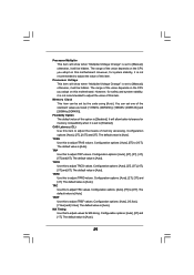
... options: [Auto], [2T], [3T] and [4T]. The range of this to adjust TRRD values. Flexibility Option The default value of the value depends on the CPU you adopt on this to [Enabled]. Memory Clock This item can set to adjust values for memory compatibility when it is [Disabled]. Configuration options: [Auto... the standard values as listed: [133MHz (DDR266)], [166MHz (DDR333)] and [200MHz (DDR400)]. TRP Use this option is set one of the value depends on the CPU you adopt on this item.
... options: [Auto], [2T], [3T] and [4T]. The range of this to adjust TRRD values. Flexibility Option The default value of the value depends on the CPU you adopt on this to [Enabled]. Memory Clock This item can set to adjust values for memory compatibility when it is [Disabled]. Configuration options: [Auto... the standard values as listed: [133MHz (DDR266)], [166MHz (DDR333)] and [200MHz (DDR400)]. TRP Use this option is set one of the value depends on the CPU you adopt on this item.

User Manual
Page 40
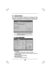
... BIOS SETUP UTILITY Advanced Chipset Settings Onboard LAN Onboard HDMI HD Audio Onboard HD Audio Front Panel CD-In Share Memory Primary Graphics Adapter CPU-NB Link Speed CPU-NB Link Width DRAM Voltage NBCORE Voltage [Enabled] [Disabled] [Auto] [Auto] [Enabled] [Auto] [PCI] [Auto] [Auto] [Auto] [Auto] To set share memory feature...
... BIOS SETUP UTILITY Advanced Chipset Settings Onboard LAN Onboard HDMI HD Audio Onboard HD Audio Front Panel CD-In Share Memory Primary Graphics Adapter CPU-NB Link Speed CPU-NB Link Width DRAM Voltage NBCORE Voltage [Enabled] [Disabled] [Auto] [Auto] [Enabled] [Auto] [PCI] [Auto] [Auto] [Auto] [Auto] To set share memory feature...
User Manual
Page 41
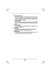
... NB link frequency. NB Link Speed This feature allows you to select NBCORE voltage. CPU - NB Link Width This feature allows you selecting CPU to select DRAM voltage. Configuration options: [Auto], [2.60V], [2.65V], [2.70V] and [2.75V]. Configuration options: [Auto], [8 bit], and [16 bit]. The default value of this to ... [PCI Express]. The default value is [Auto]. 41 Primary Graphics Adapter This item will switch the PCI Bus scanning order while searching for video card. CPU - NBCORE Voltage Use this feature is [PCI].
... NB link frequency. NB Link Speed This feature allows you to select NBCORE voltage. CPU - NB Link Width This feature allows you selecting CPU to select DRAM voltage. Configuration options: [Auto], [2.60V], [2.65V], [2.70V] and [2.75V]. Configuration options: [Auto], [8 bit], and [16 bit]. The default value of this to ... [PCI Express]. The default value is [Auto]. 41 Primary Graphics Adapter This item will switch the PCI Bus scanning order while searching for video card. CPU - NBCORE Voltage Use this feature is [PCI].
User Manual
Page 48
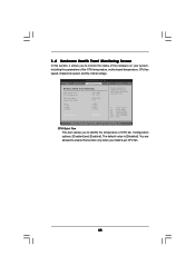
... to monitor the status of the hardware on your system, including the parameters of CPU fan. You are allowed to enable this function only when you install 4-pin CPU fan. 48 Configuration options: [Disabled] and [Enabled]. F1 F9 F10 ESC Select....54 (C) Copyright 1985-2003, American Megatrends, Inc. The default value is [Disabled]. BIOS SETUP UTILITY Main Advanced H/W Monitor Boot Security Exit Hardware Health Event Monitoring CPU Temperature M / B Temperature CPU Fan Speed Chassis Fan Speed Vcore + 3.30V + 5.00V + 12.00V : 37 C / 98 F : 31 C / 87 F : 5000 RPM : N/A : 1.532 ...
... to monitor the status of the hardware on your system, including the parameters of CPU fan. You are allowed to enable this function only when you install 4-pin CPU fan. 48 Configuration options: [Disabled] and [Enabled]. F1 F9 F10 ESC Select....54 (C) Copyright 1985-2003, American Megatrends, Inc. The default value is [Disabled]. BIOS SETUP UTILITY Main Advanced H/W Monitor Boot Security Exit Hardware Health Event Monitoring CPU Temperature M / B Temperature CPU Fan Speed Chassis Fan Speed Vcore + 3.30V + 5.00V + 12.00V : 37 C / 98 F : 31 C / 87 F : 5000 RPM : N/A : 1.532 ...

Quick Installation Guide
Page 2
...Header (USB8_9, Blue) 3 ATX Power Connector (ATXPWR1) 18 Third SATAII Connector (SATAII_3 (PORT2)) 4 CPU Heatsink Retention Module 19 Chassis Speaker Header (SPEAKER 1) 5 939-Pin CPU Socket 20 USB 2.0 Header (USB4_5, Blue) 6 CPU Fan Connector (CPU_FAN1) 21 USB 2.0 Header (USB6_7, Blue) 7 2 x 184-pin DDR DIMM Slots...Primary SATAII Connector (SATAII_1 (PORT0)) 31 DeskExpress Hot Plug Detection Header 15 USB 2.0 Header (USB10_11, Blue) (IR1) 2 ASRock 939N68PV-GLAN Motherboard Blue) nForce 630A MCP 8 2 x 184-pin DDR DIMM Slots 23 SPI Flash Memory (4Mb) (Dual Channel B: DDR3, DDR4;
...Header (USB8_9, Blue) 3 ATX Power Connector (ATXPWR1) 18 Third SATAII Connector (SATAII_3 (PORT2)) 4 CPU Heatsink Retention Module 19 Chassis Speaker Header (SPEAKER 1) 5 939-Pin CPU Socket 20 USB 2.0 Header (USB4_5, Blue) 6 CPU Fan Connector (CPU_FAN1) 21 USB 2.0 Header (USB6_7, Blue) 7 2 x 184-pin DDR DIMM Slots...Primary SATAII Connector (SATAII_1 (PORT0)) 31 DeskExpress Hot Plug Detection Header 15 USB 2.0 Header (USB10_11, Blue) (IR1) 2 ASRock 939N68PV-GLAN Motherboard Blue) nForce 630A MCP 8 2 x 184-pin DDR DIMM Slots 23 SPI Flash Memory (4Mb) (Dual Channel B: DDR3, DDR4;
Quick Installation Guide
Page 4
... CPU support lists on ASRock website without notice. 1. It delivers excellent performance with robust design conforming to ASRock's commitment to this manual will be found in the user manual presented in Floppy Drive Ribbon Cable 1 x Serial ATA (SATA) Data Cable (Optional) 1 x Serial ATA (SATA) HDD Power Cable (Optional) 1 x ASRock DVI/H I/O Shield 1 x COM Port Bracket 4 ASRock 939N68PV-GLAN...
... CPU support lists on ASRock website without notice. 1. It delivers excellent performance with robust design conforming to ASRock's commitment to this manual will be found in the user manual presented in Floppy Drive Ribbon Cable 1 x Serial ATA (SATA) Data Cable (Optional) 1 x Serial ATA (SATA) HDD Power Cable (Optional) 1 x ASRock DVI/H I/O Shield 1 x COM Port Bracket 4 ASRock 939N68PV-GLAN...

Quick Installation Guide
Page 5
... with DVI-D port - 1.2 Specifications Platform CPU Chipset Memory Hybrid Booster Expansion Slot Graphics Audio LAN Rear Panel I /O - 1 x PS/2 Mouse Port - 1 x PS/2 Keyboard Port - 1 x VGA/D-Sub Port - 1 x VGA/DVI-D Port (see CAUTION 6) - 1 x Parallel Port (ECP/EPP Support) - 4 x Ready-to-Use USB 2.0 Ports - 1 x RJ-45 Port English 5 ASRock 939N68PV-GLAN Motherboard Socket 939 for AMD AthlonTM...
... with DVI-D port - 1.2 Specifications Platform CPU Chipset Memory Hybrid Booster Expansion Slot Graphics Audio LAN Rear Panel I /O - 1 x PS/2 Mouse Port - 1 x PS/2 Keyboard Port - 1 x VGA/D-Sub Port - 1 x VGA/DVI-D Port (see CAUTION 6) - 1 x Parallel Port (ECP/EPP Support) - 4 x Ready-to-Use USB 2.0 Ports - 1 x RJ-45 Port English 5 ASRock 939N68PV-GLAN Motherboard Socket 939 for AMD AthlonTM...


