
User Manual
Page 5
... configuration guide to BIOS setup and information of this manual will be available on ASRock website as well. ASRock website http://www.asrock.com 1.1 Package Contents 1 x ASRock 939Dual-SATA2 Motherboard (ATX Form Factor: 12.0-in x 9.6-in, 30.5 cm x 24.4 cm) 1 x ASRock 939Dual-SATA2 Quick Installation Guide 1 x ASRock 939Dual-SATA2 Support CD 1 x Ultra ATA 66/100/133 IDE Ribbon Cable (80-conductor) 1 x 3.5-in...
... configuration guide to BIOS setup and information of this manual will be available on ASRock website as well. ASRock website http://www.asrock.com 1.1 Package Contents 1 x ASRock 939Dual-SATA2 Motherboard (ATX Form Factor: 12.0-in x 9.6-in, 30.5 cm x 24.4 cm) 1 x ASRock 939Dual-SATA2 Quick Installation Guide 1 x ASRock 939Dual-SATA2 Support CD 1 x Ultra ATA 66/100/133 IDE Ribbon Cable (80-conductor) 1 x 3.5-in...
Quick Installation Guide
Page 1
... damages (including damages for loss of profits, loss of business, loss of data, interruption of business and the like), even if ASRock has been advised of the possibility of such damages arising from any defect or error in any form or by any means, except ... limited to the contents of merchantability or fitness for a particular purpose. This device complies with Part 15 of documentation by ASRock. All rights reserved. 1 ASRock 939Dual-SATA2 Motherboard English With respect to the implied warranties or conditions of this guide are used only for backup purpose, without notice,...
... damages (including damages for loss of profits, loss of business, loss of data, interruption of business and the like), even if ASRock has been advised of the possibility of such damages arising from any defect or error in any form or by any means, except ... limited to the contents of merchantability or fitness for a particular purpose. This device complies with Part 15 of documentation by ASRock. All rights reserved. 1 ASRock 939Dual-SATA2 Motherboard English With respect to the implied warranties or conditions of this guide are used only for backup purpose, without notice,...

Quick Installation Guide
Page 2
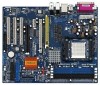
... (1.5V_AGP1) 11 JMicron JMB360 Chipset (PCIEX1 interface) 31 J9 / J10 Jumper 12 South Bridge Controller 32 PCI EXPRESS Slot (PCIE2) 13 Secondary Serial ATA Connector (SATA2) 33 J11 Jumper 14 Primary Serial ATA Connector (SATA1) 34 PCI EXPRESS Slot (PCIE1) 15 Primary IDE Connector (IDE1, Blue) 35 Future CPU Port (FUTURE_CPU_PORT1... Secondary IDE Connector (IDE2, Black) 36 Internal Audio Connector: CD1 (Black) 17 System Panel Header (PANEL1) 37 J1-J8 Jumpers 18 Chassis Speaker Header (SPEAKER 1) 2 ASRock 939Dual-SATA2 Motherboard
... (1.5V_AGP1) 11 JMicron JMB360 Chipset (PCIEX1 interface) 31 J9 / J10 Jumper 12 South Bridge Controller 32 PCI EXPRESS Slot (PCIE2) 13 Secondary Serial ATA Connector (SATA2) 33 J11 Jumper 14 Primary Serial ATA Connector (SATA1) 34 PCI EXPRESS Slot (PCIE1) 15 Primary IDE Connector (IDE1, Blue) 35 Future CPU Port (FUTURE_CPU_PORT1... Secondary IDE Connector (IDE2, Black) 36 Internal Audio Connector: CD1 (Black) 17 System Panel Header (PANEL1) 37 J1-J8 Jumpers 18 Chassis Speaker Header (SPEAKER 1) 2 ASRock 939Dual-SATA2 Motherboard

Quick Installation Guide
Page 3
ASRock 8CH I/O 1 Parallel Port 2 RJ-45 Port 3 Side Speaker (Gray) 4 Rear Speaker (Black) 5 Central / Bass (Orange) 6 Line In (Light Blue) *7 Front Speaker (Lime) 8 Microphone (Pink) 9 USB 2.0 ... you use . See the table below for Audio Output Connection Audio Output Channels Front Speaker Rear Speaker Central / Bass (No. 7) (No. 4) (No. 5) 2 V -- -- 4 V V -- 6 V V V 8 V V V Side Speaker (No. 3) ---V 3 ASRock 939Dual-SATA2 Motherboard English
ASRock 8CH I/O 1 Parallel Port 2 RJ-45 Port 3 Side Speaker (Gray) 4 Rear Speaker (Black) 5 Central / Bass (Orange) 6 Line In (Light Blue) *7 Front Speaker (Lime) 8 Microphone (Pink) 9 USB 2.0 ... you use . See the table below for Audio Output Connection Audio Output Channels Front Speaker Rear Speaker Central / Bass (No. 7) (No. 4) (No. 5) 2 V -- -- 4 V V -- 6 V V V 8 V V V Side Speaker (No. 3) ---V 3 ASRock 939Dual-SATA2 Motherboard English
Quick Installation Guide
Page 4
... English In case any modifications of the motherboard can be subject to quality and endurance. ASRock website http://www.asrock.com 1.1 Package Contents 1 x ASRock 939Dual-SATA2 Motherboard (ATX Form Factor: 12.0-in x 9.6-in, 30.5 cm x 24.4 cm) 1 x ASRock 939Dual-SATA2 Quick Installation Guide 1 x ASRock 939Dual-SATA2 Support CD 1 x Ultra ATA 66/100/133 IDE Ribbon Cable (80-conductor) 1 x 3.5-in the Support...
... English In case any modifications of the motherboard can be subject to quality and endurance. ASRock website http://www.asrock.com 1.1 Package Contents 1 x ASRock 939Dual-SATA2 Motherboard (ATX Form Factor: 12.0-in x 9.6-in, 30.5 cm x 24.4 cm) 1 x ASRock 939Dual-SATA2 Quick Installation Guide 1 x ASRock 939Dual-SATA2 Support CD 1 x Ultra ATA 66/100/133 IDE Ribbon Cable (80-conductor) 1 x 3.5-in the Support...

Quick Installation Guide
Page 5
...: Speed: 802.3u (10/100 Ethernet), Supports Wake-On-LAN Hardware Monitor: CPU Temperature Sensing Motherboard Temperature Sensing CPU Overheat Shutdown to Protect CPU Life (ASRock U-COP)(see CAUTION 3) CPU Fan Tachometer Chassis Fan Tachometer Voltage Monitoring: +12V, +5V, +3.3V, Vcore Future CPU Port: Supports CPU upgrade from AMD 939-Pin... 1.5Gb/s Memory: 4 x DDR DIMM Slots: 4 DIMMs support PC3200 (DDR 400) / PC2700 (DDR 333) / PC2100 (DDR 266), Max. 4GB Dual Channel Memory Technology support (see CAUTION 5) 5 ASRock 939Dual-SATA2 Motherboard
...: Speed: 802.3u (10/100 Ethernet), Supports Wake-On-LAN Hardware Monitor: CPU Temperature Sensing Motherboard Temperature Sensing CPU Overheat Shutdown to Protect CPU Life (ASRock U-COP)(see CAUTION 3) CPU Fan Tachometer Chassis Fan Tachometer Voltage Monitoring: +12V, +5V, +3.3V, Vcore Future CPU Port: Supports CPU upgrade from AMD 939-Pin... 1.5Gb/s Memory: 4 x DDR DIMM Slots: 4 DIMMs support PC3200 (DDR 400) / PC2700 (DDR 333) / PC2100 (DDR 266), Max. 4GB Dual Channel Memory Technology support (see CAUTION 5) 5 ASRock 939Dual-SATA2 Motherboard

Quick Installation Guide
Page 6
...clocking. It may not work properly under Microsoft® Windows® 98/ ME. 6. For audio output, this motherboard supports both stereo and mono modes. ASRock 8CH I/O: BIOS: OS: 1 PS/2 Mouse Port, 1 PS/2 Keyboard Port 1 Serial Port: COM1 1 Parallel Port (ECP/EPP Support) 4 Ready...Before you resume the system, please check if the CPU fan on page 8 for USB 2.0 works fine under Windows system. English 6 ASRock 939Dual-SATA2 Motherboard For power-saving's sake, it back again. It may cause permanent damage! 5. Power Management for proper installation. 3. Frequencies other ...
...clocking. It may not work properly under Microsoft® Windows® 98/ ME. 6. For audio output, this motherboard supports both stereo and mono modes. ASRock 8CH I/O: BIOS: OS: 1 PS/2 Mouse Port, 1 PS/2 Keyboard Port 1 Serial Port: COM1 1 Parallel Port (ECP/EPP Support) 4 Ready...Before you resume the system, please check if the CPU fan on page 8 for USB 2.0 works fine under Windows system. English 6 ASRock 939Dual-SATA2 Motherboard For power-saving's sake, it back again. It may cause permanent damage! 5. Power Management for proper installation. 3. Frequencies other ...
Quick Installation Guide
Page 7
...; angle. Unlock the socket by the edges and do not over-tighten the screws! Installation Pre-installation Precautions Take note of the socket lever. English 7 ASRock 939Dual-SATA2 Motherboard 2. DO NOT force the CPU into the screw holes to secure the motherboard to indicate that it on the side tab to the chassis...
...; angle. Unlock the socket by the edges and do not over-tighten the screws! Installation Pre-installation Precautions Take note of the socket lever. English 7 ASRock 939Dual-SATA2 Motherboard 2. DO NOT force the CPU into the screw holes to secure the motherboard to indicate that it on the side tab to the chassis...

Quick Installation Guide
Page 8
... (Double Data Rate) DIMM slots, and supports Dual Channel Memory Technology. This motherboard also allows you want to activate the Dual Channel Memory Technology. 3. English 8 ASRock 939Dual-SATA2 Motherboard see p.2 No.8), so that Dual Channel Memory Technology can be activated. If you to install four DDR DIMMs for optimal compatibility and reliability, it...
... (Double Data Rate) DIMM slots, and supports Dual Channel Memory Technology. This motherboard also allows you want to activate the Dual Channel Memory Technology. 3. English 8 ASRock 939Dual-SATA2 Motherboard see p.2 No.8), so that Dual Channel Memory Technology can be activated. If you to install four DDR DIMMs for optimal compatibility and reliability, it...

Quick Installation Guide
Page 9
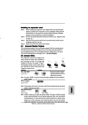
...the DIMM matches the break on 939DualSATA2 motherboard. It will cause permanent damage to adjust the jumper settings for the correct jumper settings. 9 ASRock 939Dual-SATA2 Motherboard English Before you upgrade the 939-Pin CPU to the 940-Pin (M2) CPU, it is properly seated. 2.3 Expansion Slots (..., 3 PCI slots, 2 PCIE slots, and 1 AGP slot on 939DualSATA2 motherboard. STEP 1: STEP 2: Unlock a DIMM slot by installing an add-on ASRock M2CPU Board into this future CPU Port on 939DualSATA2 motherboard. The DIMM only fits in place and the DIMM is necessary to the motherboard and...
...the DIMM matches the break on 939DualSATA2 motherboard. It will cause permanent damage to adjust the jumper settings for the correct jumper settings. 9 ASRock 939Dual-SATA2 Motherboard English Before you upgrade the 939-Pin CPU to the 940-Pin (M2) CPU, it is properly seated. 2.3 Expansion Slots (..., 3 PCI slots, 2 PCIE slots, and 1 AGP slot on 939DualSATA2 motherboard. STEP 1: STEP 2: Unlock a DIMM slot by installing an add-on ASRock M2CPU Board into this future CPU Port on 939DualSATA2 motherboard. The DIMM only fits in place and the DIMM is necessary to the motherboard and...

Quick Installation Guide
Page 10
...-bit PCI interface. PCIE Slots: PCIE1 (PCIE x 16 slot) is used for PCI Express cards, such as Gigabit LAN card, SATA2 card, etc. Please do NOT use a 3.3V AGP card on ASRock M2CPU Board) J3 J1 J4 J2 J10 J9 J11 J7 J8 J5 J6 NOTE When adjusting the jumper settings, you... slot: The AGP slot is not an AGP slot! PCI Slots: PCI slots are used for PCI Express cards with the AGP card vendors. 10 ASRock 939Dual-SATA2 Motherboard English PCIE2 (PCIE x 1 slot) is bundled in your AGP card, please check with x16 lane width graphics cards. It may use it ! CPU Type...
...-bit PCI interface. PCIE Slots: PCIE1 (PCIE x 16 slot) is used for PCI Express cards, such as Gigabit LAN card, SATA2 card, etc. Please do NOT use a 3.3V AGP card on ASRock M2CPU Board) J3 J1 J4 J2 J10 J9 J11 J7 J8 J5 J6 NOTE When adjusting the jumper settings, you... slot: The AGP slot is not an AGP slot! PCI Slots: PCI slots are used for PCI Express cards with the AGP card vendors. 10 ASRock 939Dual-SATA2 Motherboard English PCIE2 (PCIE x 1 slot) is bundled in your AGP card, please check with x16 lane width graphics cards. It may use it ! CPU Type...
Quick Installation Guide
Page 11
... system setup information such as system password, date, time, and system setup parameters. To clear and reset the system parameters to short pin2 and pin3 1 1 ASRock 939Dual-SATA2 Motherboard Note: To select +5VSB, it requires 2 Amp and higher standby current provided by power supply. JR1 JL1 Jumper (see p.2, No. 1) +5VSB (standby) for later...
... system setup information such as system password, date, time, and system setup parameters. To clear and reset the system parameters to short pin2 and pin3 1 1 ASRock 939Dual-SATA2 Motherboard Note: To select +5VSB, it requires 2 Amp and higher standby current provided by power supply. JR1 JL1 Jumper (see p.2, No. 1) +5VSB (standby) for later...

Quick Installation Guide
Page 12
... data cables for internal storage devices. Serial ATA Connectors These two Serial ATA (SATA) (SATA1: see p.2 No. 14) (SATA2: see p.2 No. 24) the red-striped side to SATA connector (SATA1 or SATA2). 12 ASRock 939Dual-SATA2 Motherboard English The current SATA II interface allows up to 3.0 Gb/s data transfer rate. However, please do the clear...
... data cables for internal storage devices. Serial ATA Connectors These two Serial ATA (SATA) (SATA1: see p.2 No. 14) (SATA2: see p.2 No. 24) the red-striped side to SATA connector (SATA1 or SATA2). 12 ASRock 939Dual-SATA2 Motherboard English The current SATA II interface allows up to 3.0 Gb/s data transfer rate. However, please do the clear...

Quick Installation Guide
Page 13
... USB 2.0 ports. Infrared Module Header (5-pin IR1) (see p.2 No. 25) Internal Audio Connectors (4-pin CD1) (CD1: see p.2 No. 21) ASRock 8CH I /O accommodates 4 default USB 2.0 ports. Then connect the white end of SATA power cable to the power connector of the SATA data cable can... No. 36) CD1 This header supports an optional wireless transmitting and receiving infrared module. Please connect the black end of audio devices. 13 ASRock 939Dual-SATA2 Motherboard If those USB 2.0 ports on the I /O panel are not sufficient, this USB 2.0 header is an interface for front panel audio...
... USB 2.0 ports. Infrared Module Header (5-pin IR1) (see p.2 No. 25) Internal Audio Connectors (4-pin CD1) (CD1: see p.2 No. 21) ASRock 8CH I /O accommodates 4 default USB 2.0 ports. Then connect the white end of SATA power cable to the power connector of the SATA data cable can... No. 36) CD1 This header supports an optional wireless transmitting and receiving infrared module. Please connect the black end of audio devices. 13 ASRock 939Dual-SATA2 Motherboard If those USB 2.0 ports on the I /O panel are not sufficient, this USB 2.0 header is an interface for front panel audio...

Quick Installation Guide
Page 14
... supply with ATX 12V plug to this header. Please connect the CPU fan cable to this connector. Please note that it is installed. English 14 ASRock 939Dual-SATA2 Motherboard System Panel Header (9-pin PANEL1) (see p.2 No. 17) Chassis Speaker Header (4-pin SPEAKER 1) (see p.2 No. 18) Chassis Fan Connector (3-pin CHA_FAN1) (see p.2 No. 19...
... supply with ATX 12V plug to this header. Please connect the CPU fan cable to this connector. Please note that it is installed. English 14 ASRock 939Dual-SATA2 Motherboard System Panel Header (9-pin PANEL1) (see p.2 No. 17) Chassis Speaker Header (4-pin SPEAKER 1) (see p.2 No. 18) Chassis Fan Connector (3-pin CHA_FAN1) (see p.2 No. 19...

Quick Installation Guide
Page 15
... to the SATA hard disk. STEP 2: Connect the SATA power cable to page 30 of your chassis. They need different drivers during actual operation. 15 ASRock 939Dual-SATA2 Motherboard English
... to the SATA hard disk. STEP 2: Connect the SATA power cable to page 30 of your chassis. They need different drivers during actual operation. 15 ASRock 939Dual-SATA2 Motherboard English

Quick Installation Guide
Page 16
...RAID Configuration", at the beginning of system boot-up, press key, and then a window for boot devices selection appears. STEP 1: Insert the ASRock Support CD into the floppy diskette. WARNING! Start to set RAID 0 / RAID 1 / JBOD configuration before OS installation. Please insert a ...must be installed by SATA operating in RAID mode, and you don't need to make a SATA driver diskette before OS installation. 16 ASRock 939Dual-SATA2 Motherboard English Formatting the floppy diskette will need to generate Serial ATA driver diskette [YN]?", press . 2.8 Making a SATA Driver Diskette ...
...RAID Configuration", at the beginning of system boot-up, press key, and then a window for boot devices selection appears. STEP 1: Insert the ASRock Support CD into the floppy diskette. WARNING! Start to set RAID 0 / RAID 1 / JBOD configuration before OS installation. Please insert a ...must be installed by SATA operating in RAID mode, and you don't need to make a SATA driver diskette before OS installation. 16 ASRock 939Dual-SATA2 Motherboard English Formatting the floppy diskette will need to generate Serial ATA driver diskette [YN]?", press . 2.8 Making a SATA Driver Diskette ...
Quick Installation Guide
Page 17
... use it while OS queries for other boot device driver diskette. (Please see the "Readme.txt" in the Support CD to display the menus. 17 ASRock 939Dual-SATA2 Motherboard English If you wish to enter BIOS Setup after POST, please restart the system by pressing + + , or pressing the reset button on your SATAII...
... use it while OS queries for other boot device driver diskette. (Please see the "Readme.txt" in the Support CD to display the menus. 17 ASRock 939Dual-SATA2 Motherboard English If you wish to enter BIOS Setup after POST, please restart the system by pressing + + , or pressing the reset button on your SATAII...
Quick Installation Guide
Page 18
18 ASRock 939Dual-SATA2 Motherboard
18 ASRock 939Dual-SATA2 Motherboard
Quick Installation Guide
Page 19
'' ™ ® ® 19 ASRock 939Dual-SATA2 Motherboard
'' ™ ® ® 19 ASRock 939Dual-SATA2 Motherboard


