User Manual
Page 5
... motherboard, please visit our website for details. 5 www.asrock.com/support/index.asp 1.1 Package Contents ASRock 890FX Deluxe5 Motherboard (ATX Form Factor: 12.0-in x 9.6-in, 30.5 cm x 24.4 cm) ASRock 890FX Deluxe5 Quick Installation Guide ASRock 890FX Deluxe5 Support CD 1 x Ultra ATA 66/100/133 IDE Ribbon...Serial ATA (SATA) Data Cables (Optional) 2 x Serial ATA (SATA) HDD Power Cables (Optional) 1 x I/O Panel Shield 1 x Front USB 3.0 Panel 4 x HDD Screws 6 x Chassis Screws 1 x Rear USB 3.0 Bracket ASRock Reminds You... Introduction Thank you for a 3.5-in our support CD for specific ...
... motherboard, please visit our website for details. 5 www.asrock.com/support/index.asp 1.1 Package Contents ASRock 890FX Deluxe5 Motherboard (ATX Form Factor: 12.0-in x 9.6-in, 30.5 cm x 24.4 cm) ASRock 890FX Deluxe5 Quick Installation Guide ASRock 890FX Deluxe5 Support CD 1 x Ultra ATA 66/100/133 IDE Ribbon...Serial ATA (SATA) Data Cables (Optional) 2 x Serial ATA (SATA) HDD Power Cables (Optional) 1 x I/O Panel Shield 1 x Front USB 3.0 Panel 4 x HDD Screws 6 x Chassis Screws 1 x Rear USB 3.0 Bracket ASRock Reminds You... Introduction Thank you for a 3.5-in our support CD for specific ...
User Manual
Page 6
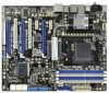
ATX Form Factor: 12.0-in x 9.6-in, 30.5 cm x 24.4 cm - Advanced V8 + 2 Power Phase Design - Northbridge: AMD 890FX - AMD Vision Black - Max. capacity of system memory: 32GB (see CAUTION 2) - PCIE x1 Gigabit LAN 10/100/1000 Mb/s - Realtek RTL8111E - Support for Socket AM3 ...
ATX Form Factor: 12.0-in x 9.6-in, 30.5 cm x 24.4 cm - Advanced V8 + 2 Power Phase Design - Northbridge: AMD 890FX - AMD Vision Black - Max. capacity of system memory: 32GB (see CAUTION 2) - PCIE x1 Gigabit LAN 10/100/1000 Mb/s - Realtek RTL8111E - Support for Socket AM3 ...

User Manual
Page 7
... audio connector - 2 x USB 2.0 headers (support 4 USB 2.0 ports) - 1 x USB 3.0 header (supports 2 USB 3.0 ports) - 1 x Dr. Debug (7-Segment Debug LED) - 1 x Clear CMOS Switch with LED - 1 x Power Switch with LED - 1 x Reset Switch with LED - HD Audio Jack: Side Speaker/Rear Speaker/Central/Bass/ Line in header - CD in /Front Speaker/Microphone (see ... 2 x Ready-to 5Gb/s - 8 x SATA3 6.0Gb/s connectors - 1 x ATA133 IDE connector (supports 2 x IDE devices) - 1 x Floppy connector - 1 x IR header - 1 x COM port header - 1 x IEEE 1394 header - 1 x HDMI_SPDIF header - 1 x Power LED header -
... audio connector - 2 x USB 2.0 headers (support 4 USB 2.0 ports) - 1 x USB 3.0 header (supports 2 USB 3.0 ports) - 1 x Dr. Debug (7-Segment Debug LED) - 1 x Clear CMOS Switch with LED - 1 x Power Switch with LED - 1 x Reset Switch with LED - HD Audio Jack: Side Speaker/Rear Speaker/Central/Bass/ Line in header - CD in /Front Speaker/Microphone (see ... 2 x Ready-to 5Gb/s - 8 x SATA3 6.0Gb/s connectors - 1 x ATA133 IDE connector (supports 2 x IDE devices) - 1 x Floppy connector - 1 x IR header - 1 x COM port header - 1 x IEEE 1394 header - 1 x HDMI_SPDIF header - 1 x Power LED header -

User Manual
Page 8
..., WHQL - OEM and Trial) Unique Feature - Turbo 50 / Turbo 60 CPU Overclocking - CPU Quiet Fan - ASRock AIWI (see CAUTION 7) - SmartView (see CAUTION 10) - CPU/Chassis/Power Fan Tachometer - BIOS Feature - 32Mb AMI UEFI Legal BIOS with overclocking, including adjusting the setting in the BIOS, ...applying Untied Overclocking Technology, or using the thirdparty overclocking tools. ASRock APP Charger (see CAUTION 11) - ErP/EuP Ready (ErP/EuP ready power supply is required) (see CAUTION 15) * For detailed product information, please visit our ...
..., WHQL - OEM and Trial) Unique Feature - Turbo 50 / Turbo 60 CPU Overclocking - CPU Quiet Fan - ASRock AIWI (see CAUTION 7) - SmartView (see CAUTION 10) - CPU/Chassis/Power Fan Tachometer - BIOS Feature - 32Mb AMI UEFI Legal BIOS with overclocking, including adjusting the setting in the BIOS, ...applying Untied Overclocking Technology, or using the thirdparty overclocking tools. ASRock APP Charger (see CAUTION 11) - ErP/EuP Ready (ErP/EuP ready power supply is required) (see CAUTION 15) * For detailed product information, please visit our ...

User Manual
Page 10
...much quickly from App store to 40% faster than ever. With APP Charger driver installed, you can easily enjoy the marvelous charging experience than before. ASRock AIWI utility introduces a new way of internet browser, is Windows® 7 / 7 64 bit / VistaTM / VistaTM 64 bit, and your ...download the free AIWI Lite from your browser version is the world's first utility to RAM (S3), hibernation mode (S4) or power off (S5). ASRock motherboards are exclusively equipped with friends on the property of charging your Apple devices, such as a game joystick to control your real...
...much quickly from App store to 40% faster than ever. With APP Charger driver installed, you can easily enjoy the marvelous charging experience than before. ASRock AIWI utility introduces a new way of internet browser, is Windows® 7 / 7 64 bit / VistaTM / VistaTM 64 bit, and your ...download the free AIWI Lite from your browser version is the world's first utility to RAM (S3), hibernation mode (S4) or power off (S5). ASRock motherboards are exclusively equipped with friends on the property of charging your Apple devices, such as a game joystick to control your real...

User Manual
Page 11
... the instability of the completed system shall be under 100 mA current consumption. According to EuP, the total AC power of the system or damage the CPU. 14. According to define the power consumption for the completed system. 13. Although this motherboard offers stepless control, it back again. Frequencies other than 50... selection, we recommend you resume the system, please check if the CPU fan on the motherboard functions properly and unplug the power cord, then plug it is not recommended to spray thermal grease between the CPU and the heatsink when you install the PC system. 15. To ...
... the instability of the completed system shall be under 100 mA current consumption. According to EuP, the total AC power of the system or damage the CPU. 14. According to define the power consumption for the completed system. 13. Although this motherboard offers stepless control, it back again. Frequencies other than 50... selection, we recommend you resume the system, please check if the CPU fan on the motherboard functions properly and unplug the power cord, then plug it is not recommended to spray thermal grease between the CPU and the heatsink when you install the PC system. 15. To ...
User Manual
Page 12
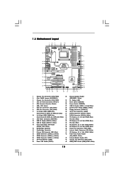
...USB 2.0 Header (USB10_11, Blue) 36 PCI Slot (PCI1) 14 Front Panel IEEE 1394 Header 37 PCI Express 2.0 x1 Slot (PCIE3; Blue) 11 ATX Power Connector (ATXPWR1) 34 PCI Slot (PCI2) 12 USB 2.0 Header (USB12_13, Blue) 35 PCI Express 2.0 x16 Slot (PCIE4; White) 18 SATA3 Connector (... 240-pin module) DDR3_B1 (64 bit, 240-FpinSBmo8d0ul0e) DDR3_B2 (64 bit, 240-pin module) 9 10 IDE1 FRONT_1394 1 USB10_11 USB12_13 PCI1 Super I/O 890FX Deluxe5 SATA3_8 PCIE4 Support 8-Core CPU SATA3 6Gb/s PCI Express 2.0 PCI2 ErP/EuP Ready Front USB 3.0 1394a RoHS NEC USB 3.0 PCIE5 COM1 1 SATA3_7 FLOPPY1...
...USB 2.0 Header (USB10_11, Blue) 36 PCI Slot (PCI1) 14 Front Panel IEEE 1394 Header 37 PCI Express 2.0 x1 Slot (PCIE3; Blue) 11 ATX Power Connector (ATXPWR1) 34 PCI Slot (PCI2) 12 USB 2.0 Header (USB12_13, Blue) 35 PCI Express 2.0 x16 Slot (PCIE4; White) 18 SATA3 Connector (... 240-pin module) DDR3_B1 (64 bit, 240-FpinSBmo8d0ul0e) DDR3_B2 (64 bit, 240-pin module) 9 10 IDE1 FRONT_1394 1 USB10_11 USB12_13 PCI1 Super I/O 890FX Deluxe5 SATA3_8 PCIE4 Support 8-Core CPU SATA3 6Gb/s PCI Express 2.0 PCI2 ErP/EuP Ready Front USB 3.0 1394a RoHS NEC USB 3.0 PCIE5 COM1 1 SATA3_7 FLOPPY1...

User Manual
Page 15
... secure the motherboard to static electricity, NEVER place your motherboard directly on a grounded antistatic pad or in the bag that the power is switched off or the power cord is an ATX form factor (12.0-in x 9.6-in, 30.5 cm x 24.4 cm) motherboard. Failure to do ...study the configuration of the following precautions before you uninstall any component, ensure that comes with the component. 5. Unplug the power cord from the power supply. Whenever you install motherboard components or change any component. 2. Installation This is detached from the wall socket before you ...
... secure the motherboard to static electricity, NEVER place your motherboard directly on a grounded antistatic pad or in the bag that the power is switched off or the power cord is an ATX form factor (12.0-in x 9.6-in, 30.5 cm x 24.4 cm) motherboard. Failure to do ...study the configuration of the following precautions before you uninstall any component, ensure that comes with the component. 5. Unplug the power cord from the power supply. Whenever you install motherboard components or change any component. 2. Installation This is detached from the wall socket before you ...

User Manual
Page 18
.... Align a DIMM on the slot such that the notch on the DIMM matches the break on the slot. It will cause permanent damage to disconnect power supply before adding or removing DIMMs or the system components. Firmly insert the DIMM into the slot at both ends fully snap back in one...
.... Align a DIMM on the slot such that the notch on the DIMM matches the break on the slot. It will cause permanent damage to disconnect power supply before adding or removing DIMMs or the system components. Firmly insert the DIMM into the slot at both ends fully snap back in one...

User Manual
Page 19
.... 1. White) is used for better thermal environment. Blue) is used for the card before you intend to install expansion cards that the power supply is switched off or the power cord is already installed in a chassis). In single VGA card mode, it is used for later use . In 3-Way CrossFireXTM mode, please...
.... 1. White) is used for better thermal environment. Blue) is used for the card before you intend to install expansion cards that the power supply is switched off or the power cord is already installed in a chassis). In single VGA card mode, it is used for later use . In 3-Way CrossFireXTM mode, please...
User Manual
Page 24
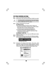
... Service Pack 2 or higher installed in your computer. Please check AMD website for details. Step 4. For Windows® 7 / VistaTM OS: Install the CATALYST Control Center. Power on your computer and boot into OS. Install the required drivers to your system, and restart your system. Please check Microsoft website for ATITM driver...
... Service Pack 2 or higher installed in your computer. Please check AMD website for details. Step 4. For Windows® 7 / VistaTM OS: Install the CATALYST Control Center. Power on your computer and boot into OS. Install the required drivers to your system, and restart your system. Please check Microsoft website for ATITM driver...

User Manual
Page 26
... jumper cap is placed on CLRCMOS1 for 5 seconds. For the detailed instruction, please refer to default setup, please turn off the computer and unplug the power cord from the power supply. With the external add-on these 2 pins.
... jumper cap is placed on CLRCMOS1 for 5 seconds. For the detailed instruction, please refer to default setup, please turn off the computer and unplug the power cord from the power supply. With the external add-on these 2 pins.

User Manual
Page 28
... the I /O panel, there are two USB 2.0 headers on this motherboard. Serial ATA (SATA) Power Cable (Optional) connect to the SATA HDD power connector connect to the power supply Please connect the black end of the power supply. Internal Audio Connectors (4-pin CD1) (CD1: see p.12 No. 40) CD-L GND GND...DUMMY 1 GND IRRX This header supports an optional wireless transmitting and receiving infrared module. Then connect the white end of SATA power cable to the power connector of SATA power cable to receive stereo audio input from sound sources such as a CD-ROM, DVD-ROM, TV tuner card, or ...
... the I /O panel, there are two USB 2.0 headers on this motherboard. Serial ATA (SATA) Power Cable (Optional) connect to the SATA HDD power connector connect to the power supply Please connect the black end of the power supply. Internal Audio Connectors (4-pin CD1) (CD1: see p.12 No. 40) CD-L GND GND...DUMMY 1 GND IRRX This header supports an optional wireless transmitting and receiving infrared module. Then connect the white end of SATA power cable to the power connector of SATA power cable to receive stereo audio input from sound sources such as a CD-ROM, DVD-ROM, TV tuner card, or ...

User Manual
Page 29
... in the Realtek Control panel. The LED is off when the system is in our manual and chassis manual to install your system using the power switch. Please follow the instruction in S1 sleep state. Connect Audio_R (RIN) to OUT2_R and Audio_L (LIN) to perform a normal restart. ...System Panel Header (9-pin PANEL1) (see p.12, No. 42) GND PRESENCE# MIC_RET OUT_RET 1 OUT2_L J_SENSE OUT2_R MIC2_R MIC2_L This is operating. Connect the power switch, reset switch and system status indicator on when the system is an interface for the front panel audio cable that allows convenient connection and...
... in the Realtek Control panel. The LED is off when the system is in our manual and chassis manual to install your system using the power switch. Please follow the instruction in S1 sleep state. Connect Audio_R (RIN) to OUT2_R and Audio_L (LIN) to perform a normal restart. ...System Panel Header (9-pin PANEL1) (see p.12, No. 42) GND PRESENCE# MIC_RET OUT_RET 1 OUT2_L J_SENSE OUT2_R MIC2_R MIC2_L This is operating. Connect the power switch, reset switch and system status indicator on when the system is an interface for the front panel audio cable that allows convenient connection and...

User Manual
Page 30
... (3-pin PLED1) (see p.12 No. 22) 1 PLEDPLED+ PLED+ Chassis Speaker Header (4-pin SPEAKER 1) (see p.12 No. 23) 1 SPEAKER DUMMY DUMMY +5V Chassis and Power Fan Connectors (4-pin CHA_FAN1) (see p.12 No. 44) FAN_SPEED_CONTROL GND +12V CHA_FAN_SPEED (3-pin CHA_FAN2) (see p.12 No. 3) (3-pin CHA_FAN3) (see p.12 No. 1) (3-pin PWR_FAN1) (see.... The LED is on when the hard drive is reading or writing data. The LED keeps blinking in S3/S4 state or S5 state (power off). The LED is on when the system is off in S1 state. Please connect the fan cables to the fan connectors and match the...
... (3-pin PLED1) (see p.12 No. 22) 1 PLEDPLED+ PLED+ Chassis Speaker Header (4-pin SPEAKER 1) (see p.12 No. 23) 1 SPEAKER DUMMY DUMMY +5V Chassis and Power Fan Connectors (4-pin CHA_FAN1) (see p.12 No. 44) FAN_SPEED_CONTROL GND +12V CHA_FAN_SPEED (3-pin CHA_FAN2) (see p.12 No. 3) (3-pin CHA_FAN3) (see p.12 No. 1) (3-pin PWR_FAN1) (see.... The LED is on when the hard drive is reading or writing data. The LED keeps blinking in S3/S4 state or S5 state (power off). The LED is on when the system is off in S1 state. Please connect the fan cables to the fan connectors and match the...

User Manual
Page 31
...CPU fan to this connector. 1 13 Though this motherboard provides 8-pin ATX 12V power connector, it can support one IEEE 1394 header (FRONT_1394) on this connector. To use the 20-pin ATX power supply, please plug your power supply along with Pin 1 and Pin 5. 1 4 IEEE 1394 Header (9-pin ...FRONT_1394) (see p.12 No. 14) 4-Pin ATX 12V Power Supply Installation 5 8 RXTPAM_0 GND RXTPBM_0 +12V GND 1 +12V RXTPBP_0 ...
...CPU fan to this connector. 1 13 Though this motherboard provides 8-pin ATX 12V power connector, it can support one IEEE 1394 header (FRONT_1394) on this connector. To use the 20-pin ATX power supply, please plug your power supply along with Pin 1 and Pin 5. 1 4 IEEE 1394 Header (9-pin ...FRONT_1394) (see p.12 No. 14) 4-Pin ATX 12V Power Supply Installation 5 8 RXTPAM_0 GND RXTPBM_0 +12V GND 1 +12V RXTPBP_0 ...

User Manual
Page 33
Step 2 Put the USB 3.0 cable and the rear USB 3.0 bracket together. Power Switch (PWRBTN) (see p.12 No. 26) Power Switch is a smart switch, allowing users to quickly reset the system. Reset Switch (RSTBTN) (see p.13 No. 17) clr CMOS Clear CMOS Switch is ...3.0 bracket. If you set up the system password. Step 3 Screw the two screws into the chassis. 2.9 Smart Switches This motherboard has three smart switches: power switch, reset switch and clear CMOS switch, allowing users to page 26 "Clear CMOS jumper" description instead. 33 Rear USB 3.0 Bracket Installation Guide Step 1 ...
Step 2 Put the USB 3.0 cable and the rear USB 3.0 bracket together. Power Switch (PWRBTN) (see p.12 No. 26) Power Switch is a smart switch, allowing users to quickly reset the system. Reset Switch (RSTBTN) (see p.13 No. 17) clr CMOS Clear CMOS Switch is ...3.0 bracket. If you set up the system password. Step 3 Screw the two screws into the chassis. 2.9 Smart Switches This motherboard has three smart switches: power switch, reset switch and clear CMOS switch, allowing users to page 26 "Clear CMOS jumper" description instead. 33 Rear USB 3.0 Bracket Installation Guide Step 1 ...

User Manual
Page 34
2.13 Dr. Debug Dr. Debug is used Power on. Reset type detection (soft/hard) AP initialization before microcode loading North Bridge initialization before microcode loading South Bridge initialization before microcode loading OEM initialization ...
2.13 Dr. Debug Dr. Debug is used Power on. Reset type detection (soft/hard) AP initialization before microcode loading North Bridge initialization before microcode loading South Bridge initialization before microcode loading OEM initialization ...

User Manual
Page 38
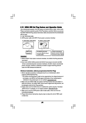
...for the action to insert and remove the SATA3 HDDs while the system is still power-on and in working condition. This section will guide you to the SATA3 hard disk. STEP 2: Connect the SATA... power cable to install the SATA3 hard disks. STEP 3: Connect one end of your chassis. If ..., it is called "Hot Swap" for the action to insert and remove the SATA3 HDDs while the system is still power-on and in RAID / AHCI mode. STEP 1: Install the SATA3 hard disks into the SATA3 HDD. 2.11 Serial...
...for the action to insert and remove the SATA3 HDDs while the system is still power-on and in working condition. This section will guide you to the SATA3 hard disk. STEP 2: Connect the SATA... power cable to install the SATA3 hard disks. STEP 3: Connect one end of your chassis. If ..., it is called "Hot Swap" for the action to insert and remove the SATA3 HDDs while the system is still power-on and in RAID / AHCI mode. STEP 1: Install the SATA3 hard disks into the SATA3 HDD. 2.11 Serial...
User Manual
Page 39
...3. Below operation procedure is available on our website: www.asrock.com 2. The latest SATA3 driver is designed only for SATA3 HDD in the product spec on our support website: www.asrock.com 4. SATA power cable with SATA 15-pin power connector interface A. Please make sure the SATA3 driver is... definitely not able to use the SATA power cable & data cable, which cannot support Hot Plug function, will...
...3. Below operation procedure is available on our website: www.asrock.com 2. The latest SATA3 driver is designed only for SATA3 HDD in the product spec on our support website: www.asrock.com 4. SATA power cable with SATA 15-pin power connector interface A. Please make sure the SATA3 driver is... definitely not able to use the SATA power cable & data cable, which cannot support Hot Plug function, will...

