User Manual
Page 5
... latest VGA cards and CPU support lists on ASRock website without notice. In this manual will be subject to the hardware installation. For the BIOS setup, please refer to AHCI mode. 1. To get better performance in Windows® 7 / 7 64-bit / VistaTM / VistaTM 64-bit, it is recommended to set the BIOS option in Storage Configuration to the "User Manual" in Floppy Drive 4 x Serial ATA (SATA) Data Cables (Optional) 2 x Serial ATA (SATA) HDD Power Cables (Optional) 1 x I/O Panel Shield 1 x Front USB 3.0 Panel 4 x HDD Screws 6 x Chassis Screws 1 x Rear USB 3.0 Bracket ASRock Reminds...
... latest VGA cards and CPU support lists on ASRock website without notice. In this manual will be subject to the hardware installation. For the BIOS setup, please refer to AHCI mode. 1. To get better performance in Windows® 7 / 7 64-bit / VistaTM / VistaTM 64-bit, it is recommended to set the BIOS option in Storage Configuration to the "User Manual" in Floppy Drive 4 x Serial ATA (SATA) Data Cables (Optional) 2 x Serial ATA (SATA) HDD Power Cables (Optional) 1 x I/O Panel Shield 1 x Front USB 3.0 Panel 4 x HDD Screws 6 x Chassis Screws 1 x Rear USB 3.0 Bracket ASRock Reminds...

User Manual
Page 10
... launch this utility, you can press key during the POST or press key to BIOS setup menu to RAM (S3), hibernation mode (S4) or power off (S5). Simply installing the APP Charger driver, it makes your iPhone charged much quickly from App store to your most up to control your PC and apple devices via Bluetooth or WiFi networks, then you keep in Flash ROM. ASRock motherboards are exclusively...
... launch this utility, you can press key during the POST or press key to BIOS setup menu to RAM (S3), hibernation mode (S4) or power off (S5). Simply installing the APP Charger driver, it makes your iPhone charged much quickly from App store to your most up to control your PC and apple devices via Bluetooth or WiFi networks, then you keep in Flash ROM. ASRock motherboards are exclusively...
User Manual
Page 12
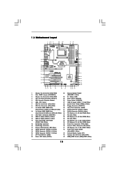
... 20 21 22 23 1 Chassis Fan Connector (CHA_FAN3) 23 Chassis Speaker Header 2 Clear CMOS Jumper (CLRCMOS1) (SPEAKER 1, White) 3 Chassis Fan Connector (CHA_FAN2) 24 Dr. Debug (LED) 4 ATX 12V Power Connector (ATX12V1) 25 Reset Switch (RSTBTN) 5 CPU Heatsink Retention Module 26 Power Switch (PWRBTN) 6 AM3+ CPU Socket 27 USB 3.0 Header (USB3_1_2, Light Blue) 7 CPU Fan Connector (CPU_FAN1) 28 System Panel Header (PANEL1, White) 8 CPU Fan Connector (CPU_FAN2) 29 Floppy Connector (FLOPPY1) 9 2 x 240-pin DDR3 DIMM Slots 30 Serial Port Connector (COM1) (Dual Channel A: DDR3_A1, DDR3_B1...
... 20 21 22 23 1 Chassis Fan Connector (CHA_FAN3) 23 Chassis Speaker Header 2 Clear CMOS Jumper (CLRCMOS1) (SPEAKER 1, White) 3 Chassis Fan Connector (CHA_FAN2) 24 Dr. Debug (LED) 4 ATX 12V Power Connector (ATX12V1) 25 Reset Switch (RSTBTN) 5 CPU Heatsink Retention Module 26 Power Switch (PWRBTN) 6 AM3+ CPU Socket 27 USB 3.0 Header (USB3_1_2, Light Blue) 7 CPU Fan Connector (CPU_FAN1) 28 System Panel Header (PANEL1, White) 8 CPU Fan Connector (CPU_FAN2) 29 Floppy Connector (FLOPPY1) 9 2 x 240-pin DDR3 DIMM Slots 30 Serial Port Connector (COM1) (Dual Channel A: DDR3_A1, DDR3_B1...
User Manual
Page 24
... item "Enable CrossFireXTM". Select "3 GPUs" and click "OK" (if you install two Radeon graphics cards). Please check Microsoft website for details. ATI Catalyst Control Center Step 6. The Catalyst Uninstaller is no need to uninstall any VGA driver installed in your Windows® taskbar. For Windows® XP OS: A. Power on your system, there is an optional download. We recommend using this utility to download it again...
... item "Enable CrossFireXTM". Select "3 GPUs" and click "OK" (if you install two Radeon graphics cards). Please check Microsoft website for details. ATI Catalyst Control Center Step 6. The Catalyst Uninstaller is no need to uninstall any VGA driver installed in your Windows® taskbar. For Windows® XP OS: A. Power on your system, there is an optional download. We recommend using this utility to download it again...

User Manual
Page 34
... loading OEM initialization before microcode loading Microcode loading AP initialization after microcode loading North Bridge initialization after microcode loading South Bridge initialization after microcode loading OEM initialization after microcode loading Cache initialization Reserved for reading the Dr. Debug codes. Configuring memory Memory initialization (other) Reserved for ASL (see the diagrams below ) Memory Installed CPU post-memory initialization is started CPU post-memory initialization. Serial Presence Detect (SPD) data reading Memory initialization. System Management Mode...
... loading OEM initialization before microcode loading Microcode loading AP initialization after microcode loading North Bridge initialization after microcode loading South Bridge initialization after microcode loading OEM initialization after microcode loading Cache initialization Reserved for reading the Dr. Debug codes. Configuring memory Memory initialization (other) Reserved for ASL (see the diagrams below ) Memory Installed CPU post-memory initialization is started CPU post-memory initialization. Serial Presence Detect (SPD) data reading Memory initialization. System Management Mode...
User Manual
Page 37
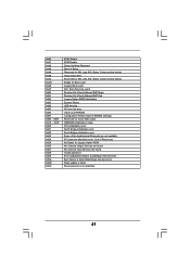
... 0xDC SCSI Detect SCSI Enable Setup Verifying Password Start of Setup Reserved for ASL (see ASL Status Codes section below) Setup Input Wait Reserved for ASL (see ASL Status Codes section below) Ready To Boot event Legacy Boot event Exit Boot Services event Runtime Set Virtual Address MAP Begin Runtime Set Virtual Address MAP End Legacy Option ROM Initialization System Reset USB hot plug PCI bus hot plug Clean-up of NVRAM Configuration Reset (reset of the Architectural Protocols...
... 0xDC SCSI Detect SCSI Enable Setup Verifying Password Start of Setup Reserved for ASL (see ASL Status Codes section below) Setup Input Wait Reserved for ASL (see ASL Status Codes section below) Ready To Boot event Legacy Boot event Exit Boot Services event Runtime Set Virtual Address MAP Begin Runtime Set Virtual Address MAP End Legacy Option ROM Initialization System Reset USB hot plug PCI bus hot plug Clean-up of NVRAM Configuration Reset (reset of the Architectural Protocols...
User Manual
Page 39
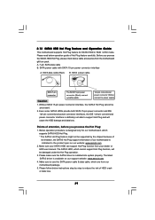
...-pin power connector (Black) connect to SATA3 HDD 1x4-pin conventional power connector (White) connect to reduce the risk of Hot Plug feature carefully. Even some SATA3 HDDs provide both SATA 15-pin power connector and IDE 1x4-pin conventional power connector interfaces, the IDE 1x4-pin conventional power connector interface is indicated in RAID / AHCI mode. Please make sure the SATA3 driver is available on our website: www.asrock.com 2. 2.13 SATA3 HDD Hot Plug Feature and Operation Guide This motherboard supports...
...-pin power connector (Black) connect to SATA3 HDD 1x4-pin conventional power connector (White) connect to reduce the risk of Hot Plug feature carefully. Even some SATA3 HDDs provide both SATA 15-pin power connector and IDE 1x4-pin conventional power connector interfaces, the IDE 1x4-pin conventional power connector interface is indicated in RAID / AHCI mode. Please make sure the SATA3 driver is available on our website: www.asrock.com 2. 2.13 SATA3 HDD Hot Plug Feature and Operation Guide This motherboard supports...
User Manual
Page 41
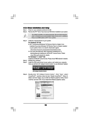
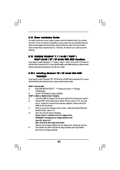
Therefore, the drivers you install can be auto-detected and listed on the support CD driver page. Enter UEFI SETUP UTILITY Advanced screen Storage Configuration. A. Please select CD- When you want to install Windows® 7 / 7 64-bit / VistaTM / VistaTM 64-bit / XP / XP 64-bit on a RAID disk composed of 2 or more SATA3 HDDs with RAID functions, please follow below procedures according to the OS you install. 2.15.1 Installing Windows® XP / XP 64-bit With RAID Functions...
Therefore, the drivers you install can be auto-detected and listed on the support CD driver page. Enter UEFI SETUP UTILITY Advanced screen Storage Configuration. A. Please select CD- When you want to install Windows® 7 / 7 64-bit / VistaTM / VistaTM 64-bit / XP / XP 64-bit on a RAID disk composed of 2 or more SATA3 HDDs with RAID functions, please follow below procedures according to the OS you install. 2.15.1 Installing Windows® XP / XP 64-bit With RAID Functions...

User Manual
Page 55
... to use SATA3_1 to install SATA ODD driver on SATA3_5 or SATA3_6 port. This will minimum your bootable device. The default value is [Enabled]. The default value of this item to [Yes]. Use this item to RAID mode, it is suggested to SATA3_6 ports for your boot time and get the best performance. SATA IDE Combined Mode This item is for Marvell SATA3_7 and SATA3_8/eSATA ports. Configuration options: [IDE Mode], [AHCI Mode] and [Disabled]. 3.4.4 Storage Configuration SATA Controller...
... to use SATA3_1 to install SATA ODD driver on SATA3_5 or SATA3_6 port. This will minimum your bootable device. The default value is [Enabled]. The default value of this item to [Yes]. Use this item to RAID mode, it is suggested to SATA3_6 ports for your boot time and get the best performance. SATA IDE Combined Mode This item is for Marvell SATA3_7 and SATA3_8/eSATA ports. Configuration options: [IDE Mode], [AHCI Mode] and [Disabled]. 3.4.4 Storage Configuration SATA Controller...

User Manual
Page 58
... [Disabled] to enter OS. [UEFI Setup Only] - 3.4.7 USB Configuration USB 2.0 Controller Use this item to enable or disable the use of USB 3.0 controller. USB 3.0 Controller Use this item to enable or disable legacy support for USB devices. Legacy USB 3.0 Support Use this option to below descriptions for legacy USB. [Auto] - The default value is [Enabled]. Enables legacy support if USB devices are four confi guration options: [Enabled], [Auto], [Disabled] and [UEFI Setup Only]. If you have USB compatibility issue, it is selected. Legacy USB Support Use this option to enable...
... [Disabled] to enter OS. [UEFI Setup Only] - 3.4.7 USB Configuration USB 2.0 Controller Use this item to enable or disable the use of USB 3.0 controller. USB 3.0 Controller Use this item to enable or disable legacy support for USB devices. Legacy USB 3.0 Support Use this option to below descriptions for legacy USB. [Auto] - The default value is [Enabled]. Enables legacy support if USB devices are four confi guration options: [Enabled], [Auto], [Disabled] and [UEFI Setup Only]. If you have USB compatibility issue, it is selected. Legacy USB Support Use this option to enable...
User Manual
Page 63
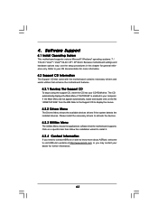
... motherboard settings and hardware options vary, use the setup procedures in the Support CD to activate the devices. 4.2.3 Utilities Menu The Utilities Menu shows the applications software that enhance the motherboard features. 4.2.1 Running The Support CD To begin using the support CD, insert the CD into your CD-ROM drive. 4. Please install the necessary drivers to display the menus. 4.2.2 Drivers Menu The Drivers Menu shows the available devices drivers if the system detects the installed devices. Software Support 4.1 Install Operating System This motherboard supports...
... motherboard settings and hardware options vary, use the setup procedures in the Support CD to activate the devices. 4.2.3 Utilities Menu The Utilities Menu shows the applications software that enhance the motherboard features. 4.2.1 Running The Support CD To begin using the support CD, insert the CD into your CD-ROM drive. 4. Please install the necessary drivers to display the menus. 4.2.2 Drivers Menu The Drivers Menu shows the available devices drivers if the system detects the installed devices. Software Support 4.1 Install Operating System This motherboard supports...

Quick Installation Guide
Page 2
... Slot (PCIE3; Motherboard Layout 1 Chassis Fan Connector (CHA_FAN3) 23 Chassis Speaker Header 2 Clear CMOS Jumper (CLRCMOS1) (SPEAKER 1, White) 3 Chassis Fan Connector (CHA_FAN2) 24 Dr. Debug (LED) 4 ATX 12V Power Connector (ATX12V1) 25 Reset Switch (RSTBTN) 5 CPU Heatsink Retention Module 26 Power Switch (PWRBTN) 6 AM3+ CPU Socket 27 USB 3.0 Header (USB3_1_2, Light Blue) 7 CPU Fan Connector (CPU_FAN1) 28 System Panel Header (PANEL1, White) 8 CPU Fan Connector (CPU_FAN2) 29 Floppy Connector (FLOPPY1) 9 2 x 240-pin DDR3 DIMM Slots 30 Serial Port Connector (COM1) (Dual Channel...
... Slot (PCIE3; Motherboard Layout 1 Chassis Fan Connector (CHA_FAN3) 23 Chassis Speaker Header 2 Clear CMOS Jumper (CLRCMOS1) (SPEAKER 1, White) 3 Chassis Fan Connector (CHA_FAN2) 24 Dr. Debug (LED) 4 ATX 12V Power Connector (ATX12V1) 25 Reset Switch (RSTBTN) 5 CPU Heatsink Retention Module 26 Power Switch (PWRBTN) 6 AM3+ CPU Socket 27 USB 3.0 Header (USB3_1_2, Light Blue) 7 CPU Fan Connector (CPU_FAN1) 28 System Panel Header (PANEL1, White) 8 CPU Fan Connector (CPU_FAN2) 29 Floppy Connector (FLOPPY1) 9 2 x 240-pin DDR3 DIMM Slots 30 Serial Port Connector (COM1) (Dual Channel...

Quick Installation Guide
Page 7
.... Boot Failure Guard (B.F.G.) - SmartView (see CAUTION 13) - FCC, CE, WHQL - ACPI 1.1 Compliance Wake Up Events - BIOS Feature - 32Mb AMI UEFI Legal BIOS with overclocking, including adjusting the setting in the BIOS, applying Untied Overclocking Technology, or using the thirdparty overclocking tools. CPU, VCCM, NB, SB Voltage Multi-adjustment Support CD - CPU Frequency Stepless Control (see CAUTION 11) - CPU Temperature Sensing Monitor - Chassis Temperature Sensing - It should be done at your system. English 7 ASRock 890FX Deluxe5 Motherboard
.... Boot Failure Guard (B.F.G.) - SmartView (see CAUTION 13) - FCC, CE, WHQL - ACPI 1.1 Compliance Wake Up Events - BIOS Feature - 32Mb AMI UEFI Legal BIOS with overclocking, including adjusting the setting in the BIOS, applying Untied Overclocking Technology, or using the thirdparty overclocking tools. CPU, VCCM, NB, SB Voltage Multi-adjustment Support CD - CPU Frequency Stepless Control (see CAUTION 11) - CPU Temperature Sensing Monitor - Chassis Temperature Sensing - It should be done at your system. English 7 ASRock 890FX Deluxe5 Motherboard

Quick Installation Guide
Page 9
... world's first utility to access ASRock Instant Flash. ASRock APP Charger. ASRock XFast USB can start page for a more personal Internet experience. ASRock Instant Flash is just to install the ASRock AIWI utility either from ASRock official website or ASRock software support CD to your motherboard, and also download the free AIWI Lite from your Apple devices, such as a game joystick to RAM (S3), hibernation mode (S4) or power off (S5). Connecting your PC games...
... world's first utility to access ASRock Instant Flash. ASRock APP Charger. ASRock XFast USB can start page for a more personal Internet experience. ASRock Instant Flash is just to install the ASRock AIWI utility either from ASRock official website or ASRock software support CD to your motherboard, and also download the free AIWI Lite from your Apple devices, such as a game joystick to RAM (S3), hibernation mode (S4) or power off (S5). Connecting your PC games...
Quick Installation Guide
Page 20
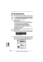
... have Windows® XP Service Pack 2 or higher installed in your system, there is an optional download. Select "3 GPUs" and click "OK" (if you install two Radeon graphics cards). Install the required drivers to your system, and restart your system. ATI Catalyst Control Center Step 6. 2.5.2 Driver Installation and Setup Step 1. Please check AMD website for ATITM driver updates. Power on your computer. We recommend using this utility to uninstall any VGA driver installed...
... have Windows® XP Service Pack 2 or higher installed in your system, there is an optional download. Select "3 GPUs" and click "OK" (if you install two Radeon graphics cards). Install the required drivers to your system, and restart your system. ATI Catalyst Control Center Step 6. 2.5.2 Driver Installation and Setup Step 1. Please check AMD website for ATITM driver updates. Power on your computer. We recommend using this utility to uninstall any VGA driver installed...

Quick Installation Guide
Page 31
... Not used to provide code information, which makes troubleshooting even easier. System Management Mode (SMM) initialization 31 ASRock 890FX Deluxe5 Motherboard English Serial Presence Detect (SPD) data reading Memory initialization. Application Processor(s) (AP) initialization CPU post-memory initialization. Configuring memory Memory initialization (other) Reserved for future AMI SEC error codes Microcode not found Microcode not loaded PEI Core is started Pre-memory CPU initialization is started Pre-memory CPU initialization (CPU module specific) Pre-memory CPU initialization (CPU...
... Not used to provide code information, which makes troubleshooting even easier. System Management Mode (SMM) initialization 31 ASRock 890FX Deluxe5 Motherboard English Serial Presence Detect (SPD) data reading Memory initialization. Application Processor(s) (AP) initialization CPU post-memory initialization. Configuring memory Memory initialization (other) Reserved for future AMI SEC error codes Microcode not found Microcode not loaded PEI Core is started Pre-memory CPU initialization is started Pre-memory CPU initialization (CPU module specific) Pre-memory CPU initialization (CPU...
Quick Installation Guide
Page 37
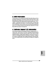
The Support CD that will display the Main Menu automatically if "AUTORUN" is enabled in the Support CD to display the menus. 37 ASRock 890FX Deluxe5 Motherboard English If the Main Menu does not appear automatically, locate and doubleclick on the file "ASSETUP.EXE" from the "BIN" folder in your CDROM drive. When you start up the computer, please press during the Power-On-Self-Test (POST) to the User Manual (PDF file) contained...
The Support CD that will display the Main Menu automatically if "AUTORUN" is enabled in the Support CD to display the menus. 37 ASRock 890FX Deluxe5 Motherboard English If the Main Menu does not appear automatically, locate and doubleclick on the file "ASSETUP.EXE" from the "BIN" folder in your CDROM drive. When you start up the computer, please press during the Power-On-Self-Test (POST) to the User Manual (PDF file) contained...
RAID Installation Guide
Page 4
... install Windows XP / XP 64-bit on a RAID disk composed of Windows setup, press F6 to boot your data first before you need to the BIOS RAID installation guide part in this RAID installation guide for boot devices selection appears. D. The system will see the message on your system. WARNING!! Please select CD-ROM as the boot device. When 4 Set the "SATA Operation Mode" option to "Clear Disk Data" or not. STEP 3: Use "RAID Installation Guide" to set RAID configuration, you can start Please insert a floppy...
... install Windows XP / XP 64-bit on a RAID disk composed of Windows setup, press F6 to boot your data first before you need to the BIOS RAID installation guide part in this RAID installation guide for boot devices selection appears. D. The system will see the message on your system. WARNING!! Please select CD-ROM as the boot device. When 4 Set the "SATA Operation Mode" option to "Clear Disk Data" or not. STEP 3: Use "RAID Installation Guide" to set RAID configuration, you can start Please insert a floppy...
RAID Installation Guide
Page 5
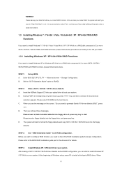
... document for proper configuration. STEP 3: Install Windows 7 / 7 64-bit / Vista / Vista 64-bit OS on a RAID disk composed of 2 or more SATA / SATAII / SATA3 HDDs with RAID functions, please follow below steps. Enter BIOS SETUP UTILITY → Advanced screen →Storage Configuration. B. Select your system. 5 Before you start to configure RAID function, you want to set RAID configuration. A. prompted, insert the SATA / SATAII / SATA3 driver diskette containing AMD RAID driver. STEP 1: Set up BIOS. After reading the floppy disk, the driver will be...
... document for proper configuration. STEP 3: Install Windows 7 / 7 64-bit / Vista / Vista 64-bit OS on a RAID disk composed of 2 or more SATA / SATAII / SATA3 HDDs with RAID functions, please follow below steps. Enter BIOS SETUP UTILITY → Advanced screen →Storage Configuration. B. Select your system. 5 Before you start to configure RAID function, you want to set RAID configuration. A. prompted, insert the SATA / SATAII / SATA3 driver diskette containing AMD RAID driver. STEP 1: Set up BIOS. After reading the floppy disk, the driver will be...

RAID Installation Guide
Page 10
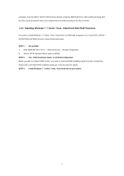
... the default browser. RAIDXpert uses this guide carefully and follow the instructions below to configure and manage RAID functions. 2.1 Components of all AMD SB850 SATA logical drives that may be present on a network. Boot the PC or server, launch Windows, and log in folder _jvm under Windows environment. Please read this private JRE to launch it . 4. When the first installation screen appears, choose an installer language...
... the default browser. RAIDXpert uses this guide carefully and follow the instructions below to configure and manage RAID functions. 2.1 Components of all AMD SB850 SATA logical drives that may be present on a network. Boot the PC or server, launch Windows, and log in folder _jvm under Windows environment. Please read this private JRE to launch it . 4. When the first installation screen appears, choose an installer language...


