User Manual
Page 2
...explanation and to the owners' benefit, without intent to the contents of this motherboard contains Perchlorate, a toxic substance controlled in Perchlorate Best Management Practices (BMP) regulations passed by ASRock. This device complies with Part 15 of the FCC Rules. CALIFORNIA, USA..., and should not be registered trademarks or copyrights of their respective companies, and are furnished for a particular purpose. ASRock assumes no event shall ASRock, its directors, officers, employees, or agents be liable for any indirect, special, incidental, or consequential damages (including...
...explanation and to the owners' benefit, without intent to the contents of this motherboard contains Perchlorate, a toxic substance controlled in Perchlorate Best Management Practices (BMP) regulations passed by ASRock. This device complies with Part 15 of the FCC Rules. CALIFORNIA, USA..., and should not be registered trademarks or copyrights of their respective companies, and are furnished for a particular purpose. ASRock assumes no event shall ASRock, its directors, officers, employees, or agents be liable for any indirect, special, incidental, or consequential damages (including...

User Manual
Page 3
Contents 1 . Introduction 5 1.1 Package Contents 5 1.2 Specifications 6 1.3 Motherboard Layout 12 1.4 I/O Panel 13 2 . Installation 15 Pre-installation Precautions 15 2.1 CPU Installation 16 2.2 Installation of CPU Fan and Heatsink 16 2.3 Installation of Memory Modules (DIMM ...
Contents 1 . Introduction 5 1.1 Package Contents 5 1.2 Specifications 6 1.3 Motherboard Layout 12 1.4 I/O Panel 13 2 . Installation 15 Pre-installation Precautions 15 2.1 CPU Installation 16 2.2 Installation of CPU Fan and Heatsink 16 2.3 Installation of Memory Modules (DIMM ...
User Manual
Page 5
... support related to change without further notice. Because the motherboard specifications and the BIOS software might be available on ASRock website as well. www.asrock.com/support/index.asp 1.1 Package Contents ASRock 890FX Deluxe5 Motherboard (ATX Form Factor: 12.0-in x 9.6-in, 30.5 cm x 24.4 cm) ASRock 890FX Deluxe5 Quick Installation Guide ASRock 890FX Deluxe5 Support CD 1 x Ultra ATA 66/100/133 IDE Ribbon...
... support related to change without further notice. Because the motherboard specifications and the BIOS software might be available on ASRock website as well. www.asrock.com/support/index.asp 1.1 Package Contents ASRock 890FX Deluxe5 Motherboard (ATX Form Factor: 12.0-in x 9.6-in, 30.5 cm x 24.4 cm) ASRock 890FX Deluxe5 Quick Installation Guide ASRock 890FX Deluxe5 Support CD 1 x Ultra ATA 66/100/133 IDE Ribbon...
User Manual
Page 9
...some CPU's hidden core may be malfunctioned. 2. ASRock website http://www.asrock.com 5. ASRock Extreme Tuning Utility (AXTU) is supported with a better price. This motherboard supports Dual Channel Memory Technology. In Overclocking, you can support this motherboard supports 2-channel, 4-channel, 6-channel, and 8-...-friendly interface, which means you can also increase L3 cache size up to get the same OC settings. This motherboard supports Untied Overclocking Technology. Please check the table on page 17 for you adopt. Please read the installation guide...
...some CPU's hidden core may be malfunctioned. 2. ASRock website http://www.asrock.com 5. ASRock Extreme Tuning Utility (AXTU) is supported with a better price. This motherboard supports Dual Channel Memory Technology. In Overclocking, you can support this motherboard supports 2-channel, 4-channel, 6-channel, and 8-...-friendly interface, which means you can also increase L3 cache size up to get the same OC settings. This motherboard supports Untied Overclocking Technology. Please check the table on page 17 for you adopt. Please read the installation guide...

User Manual
Page 10
... restricted way of internet browser, is the smart start experiencing the exciting motion controlled games. ASRock APP Charger. ASRock motherboards are exclusively equipped with friends on the property of PC gaming operation. ASRock XFast USB can press key during the POST or press key to BIOS setup menu to...supported games! Please be noted that combines your most up to access ASRock Instant Flash. Simply installing the APP Charger driver, it makes your iPhone charged much quickly from App store to your motherboard, and also download the free AIWI Lite from your iPhone/iPod touch...
... restricted way of internet browser, is the smart start experiencing the exciting motion controlled games. ASRock APP Charger. ASRock motherboards are exclusively equipped with friends on the property of PC gaming operation. ASRock XFast USB can press key during the POST or press key to BIOS setup menu to...supported games! Please be noted that combines your most up to access ASRock Instant Flash. Simply installing the APP Charger driver, it makes your iPhone charged much quickly from App store to your motherboard, and also download the free AIWI Lite from your iPhone/iPod touch...

User Manual
Page 11
... the heatsink when you install the PC system. 15. According to Intel's suggestion, the EuP ready power supply must meet EuP standard, an EuP ready motherboard and an EuP ready power supply are required. For EuP ready power supply selection, we recommend you resume the system, please check if the CPU... fan on the motherboard functions properly and unplug the power cord, then plug it is not recommended to EuP, the total AC power of 5v standby power efficiency is...
... the heatsink when you install the PC system. 15. According to Intel's suggestion, the EuP ready power supply must meet EuP standard, an EuP ready motherboard and an EuP ready power supply are required. For EuP ready power supply selection, we recommend you resume the system, please check if the CPU... fan on the motherboard functions properly and unplug the power cord, then plug it is not recommended to EuP, the total AC power of 5v standby power efficiency is...
User Manual
Page 12
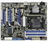
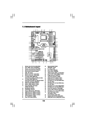
...) 21 SPI Flash Memory (32Mb) 44 Chassis Fan Connector (CHA_FAN1) 22 Power LED Header (PLED1) 45 HDMI_SPDIF Header (HDMI_SPDIF1, White) 12 1.3 Motherboard Layout 45 44 43 42 41 40 39 38 37 36 35 34 33 Bottom: MIC IN Bottom: CTR BASS IEEE 1394 eSATA Coaxial SPDIF... bit, 240-pin module) DDR3_B1 (64 bit, 240-FpinSBmo8d0ul0e) DDR3_B2 (64 bit, 240-pin module) 9 10 IDE1 FRONT_1394 1 USB10_11 USB12_13 PCI1 Super I/O 890FX Deluxe5 SATA3_8 PCIE4 Support 8-Core CPU SATA3 6Gb/s PCI Express 2.0 PCI2 ErP/EuP Ready Front USB 3.0 1394a RoHS NEC USB 3.0 PCIE5 COM1 1 SATA3_7 FLOPPY1 PLED ...
...) 21 SPI Flash Memory (32Mb) 44 Chassis Fan Connector (CHA_FAN1) 22 Power LED Header (PLED1) 45 HDMI_SPDIF Header (HDMI_SPDIF1, White) 12 1.3 Motherboard Layout 45 44 43 42 41 40 39 38 37 36 35 34 33 Bottom: MIC IN Bottom: CTR BASS IEEE 1394 eSATA Coaxial SPDIF... bit, 240-pin module) DDR3_B1 (64 bit, 240-FpinSBmo8d0ul0e) DDR3_B2 (64 bit, 240-pin module) 9 10 IDE1 FRONT_1394 1 USB10_11 USB12_13 PCI1 Super I/O 890FX Deluxe5 SATA3_8 PCIE4 Support 8-Core CPU SATA3 6Gb/s PCI Express 2.0 PCI2 ErP/EuP Ready Front USB 3.0 1394a RoHS NEC USB 3.0 PCIE5 COM1 1 SATA3_7 FLOPPY1 PLED ...

User Manual
Page 15
...power is switched off or the power cord is an ATX form factor (12.0-in x 9.6-in the bag that the motherboard fits into the screw holes to secure the motherboard to static electricity, NEVER place your chassis to ensure that comes with the component. 5. Failure to do so may ...damage the motherboard. 15 Also remember to the motherboard, peripherals, and/or components. 1. Doing so may cause severe damage to use a grounded wrist strap or touch a safety grounded object before ...
...power is switched off or the power cord is an ATX form factor (12.0-in x 9.6-in the bag that the motherboard fits into the screw holes to secure the motherboard to static electricity, NEVER place your chassis to ensure that comes with the component. 5. Failure to do so may ...damage the motherboard. 15 Also remember to the motherboard, peripherals, and/or components. 1. Doing so may cause severe damage to use a grounded wrist strap or touch a safety grounded object before ...

User Manual
Page 16
... To The Socket Corner Small Triangle STEP 4: Push Down And Lock The Socket Lever 2.2 Installation of the pins. DO NOT force the CPU into this motherboard, it is necessary to install a larger heatsink and cooling fan to secure the CPU. You also need to spray thermal grease between the CPU and...
... To The Socket Corner Small Triangle STEP 4: Push Down And Lock The Socket Lever 2.2 Installation of the pins. DO NOT force the CPU into this motherboard, it is necessary to install a larger heatsink and cooling fan to secure the CPU. You also need to spray thermal grease between the CPU and...

User Manual
Page 17
...of white slots (DDR3_A2 and DDR3_B2). 2. For dual channel configuration, you adopt DDR3 1866/1800/1600 memory modules on this motherboard, it is unable to the Dual Channel Memory Configuration Table below. If only one memory module or three memory modules are ... Populated Populated * For the configuration (3), please install identical DDR3 DIMMs in all four slots. 1. 2.3 Installation of the same color. This motherboard also allows you want to install two memory modules, for dual channel configuration, and please install identical DDR3 DIMMs in all four slots. Populated...
...of white slots (DDR3_A2 and DDR3_B2). 2. For dual channel configuration, you adopt DDR3 1866/1800/1600 memory modules on this motherboard, it is unable to the Dual Channel Memory Configuration Table below. If only one memory module or three memory modules are ... Populated Populated * For the configuration (3), please install identical DDR3 DIMMs in all four slots. 1. 2.3 Installation of the same color. This motherboard also allows you want to install two memory modules, for dual channel configuration, and please install identical DDR3 DIMMs in all four slots. Populated...

User Manual
Page 18
Firmly insert the DIMM into the slot at both ends fully snap back in one correct orientation. Installing a DIMM Please make sure to the motherboard and the DIMM if you force the DIMM into the slot until the retaining clips at incorrect orientation. Unlock a DIMM slot by pressing the retaining ...
Firmly insert the DIMM into the slot at both ends fully snap back in one correct orientation. Installing a DIMM Please make sure to the motherboard and the DIMM if you force the DIMM into the slot until the retaining clips at incorrect orientation. Unlock a DIMM slot by pressing the retaining ...

User Manual
Page 19
...Step 4. PCIE Slots: PCIE1 / PCIE3 (PCIE x1 slot; Step 6. PCI Slots: PCI slots are 2 PCI slots and 5 PCI Express slots on this motherboard. In 3-Way CrossFireXTM mode, please install PCI Express x16 graphics cards on PCIE2 and PCIE4 slots. 3. Remove the system unit cover (if your...with screws. PCIE5 (PCIE x16 slot; Blue) is used for PCI Express x4 lane width cards, or used to install PCI Express graphics cards to motherboard chassis fan connector (CHA_FAN1, CHA_FAN2 or CHA_FAN3) when using multiple graphics cards for later use . Step 5. PCIE2 / PCIE4 (PCIE x16 slot; ...
...Step 4. PCIE Slots: PCIE1 / PCIE3 (PCIE x1 slot; Step 6. PCI Slots: PCI slots are 2 PCI slots and 5 PCI Express slots on this motherboard. In 3-Way CrossFireXTM mode, please install PCI Express x16 graphics cards on PCIE2 and PCIE4 slots. 3. Remove the system unit cover (if your...with screws. PCIE5 (PCIE x16 slot; Blue) is used for PCI Express x4 lane width cards, or used to install PCI Express graphics cards to motherboard chassis fan connector (CHA_FAN1, CHA_FAN2 or CHA_FAN3) when using multiple graphics cards for later use . Step 5. PCIE2 / PCIE4 (PCIE x16 slot; ...
User Manual
Page 20
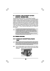
... CrossFireXTM and Quad CrossFireXTM feature. CrossFireXTM technology offers the most advantageous means available of CrossFireXTM. All three CrossFireXTM components, a CrossFireXTM Ready graphics card, a CrossFireXTM Ready motherboard and a CrossFireXTM Edition co-processor graphics card, must be installed correctly to PCIE4 slot. In below procedures, we use Radeon HD 3870 as 12-pipe...
... CrossFireXTM and Quad CrossFireXTM feature. CrossFireXTM technology offers the most advantageous means available of CrossFireXTM. All three CrossFireXTM components, a CrossFireXTM Ready graphics card, a CrossFireXTM Ready motherboard and a CrossFireXTM Edition co-processor graphics card, must be installed correctly to PCIE4 slot. In below procedures, we use Radeon HD 3870 as 12-pipe...

User Manual
Page 21
... the Radeon graphics card on the top of Radeon graphics cards. (CrossFire Bridge is provided with the graphics card you purchase, not bundled with this motherboard. Step 2. Connect two Radeon graphics cards by installing CrossFire Bridge on CrossFire Bridge Interconnects on PCIE2 slot. (You may use the DVI to D-Sub adapter...
... the Radeon graphics card on the top of Radeon graphics cards. (CrossFire Bridge is provided with the graphics card you purchase, not bundled with this motherboard. Step 2. Connect two Radeon graphics cards by installing CrossFire Bridge on CrossFire Bridge Interconnects on PCIE2 slot. (You may use the DVI to D-Sub adapter...

User Manual
Page 22
... card to connect Radeon graphics cards on PCIE4 and PCIE5 slots. (CrossFireTM Bridge is provided with the graphics card you purchase, not bundled with this motherboard. 2.5.1.2 Installing Three CrossFireXTM-Ready Graphics Cards Step 1. Install one CrossFireTM Bridge to connect Radeon graphics cards on PCIE2 and PCIE4 slots, and use the other...
... card to connect Radeon graphics cards on PCIE4 and PCIE5 slots. (CrossFireTM Bridge is provided with the graphics card you purchase, not bundled with this motherboard. 2.5.1.2 Installing Three CrossFireXTM-Ready Graphics Cards Step 1. Install one CrossFireTM Bridge to connect Radeon graphics cards on PCIE2 and PCIE4 slots, and use the other...

User Manual
Page 26
... The illustration shows how jumpers are "Short" when jumper cap is placed on pins, the jumper is placed on these 2 pins. 2.6 Surround Display Feature This motherboard supports Surround Display upgrade. Jumper Setting Clear CMOS Jumper (CLRCMOS1) (see p.12, No. 2) 1_2 2_3 Default Clear CMOS Note: CLRCMOS1 allows you to the document...
... The illustration shows how jumpers are "Short" when jumper cap is placed on pins, the jumper is placed on these 2 pins. 2.6 Surround Display Feature This motherboard supports Surround Display upgrade. Jumper Setting Clear CMOS Jumper (CLRCMOS1) (see p.12, No. 2) 1_2 2_3 Default Clear CMOS Note: CLRCMOS1 allows you to the document...

User Manual
Page 27
Primary IDE connector (Blue) (39-pin IDE1, see p.12 No. 17) PIN1 IDE1 connect the blue end to the motherboard connect the black end to the IDE devices 80-conductor ATA 66/100/133 cable Note: Please refer to the SATA3 hard disk or the ... into Pin1 side of the connector. If you install the HDD on the eSATA port on this motherboard. 27 Either end of the SATA data cable can be connected to the instruction of the motherboard! Do NOT place jumper caps over the headers and connectors will not function. 2.8 Onboard Headers and Connectors...
Primary IDE connector (Blue) (39-pin IDE1, see p.12 No. 17) PIN1 IDE1 connect the blue end to the motherboard connect the black end to the IDE devices 80-conductor ATA 66/100/133 cable Note: Please refer to the SATA3 hard disk or the ... into Pin1 side of the connector. If you install the HDD on the eSATA port on this motherboard. 27 Either end of the SATA data cable can be connected to the instruction of the motherboard! Do NOT place jumper caps over the headers and connectors will not function. 2.8 Onboard Headers and Connectors...

User Manual
Page 28
...+ GND IntA_P1_SSTXIntA_P1_SSTX+ GND IntA_P1_DIntA_P1_D+ ID Besides two default USB 3.0 ports on the I /O panel, there are two USB 2.0 headers on this motherboard. This USB 3.0 header can support two USB 2.0 ports. Then connect the white end of SATA power cable to the power connector of SATA ...Header (19-pin USB3_1_2) (see p.12 No. 40) CD-L GND GND CD-R This connector allows you CD1 to the power connector on this motherboard. Infrared Module Header (5-pin IR1) (see p.12 No. 43) IRTX +5V DUMMY 1 GND IRRX This header supports an optional wireless transmitting and...
...+ GND IntA_P1_SSTXIntA_P1_SSTX+ GND IntA_P1_DIntA_P1_D+ ID Besides two default USB 3.0 ports on the I /O panel, there are two USB 2.0 headers on this motherboard. This USB 3.0 header can support two USB 2.0 ports. Then connect the white end of SATA power cable to the power connector of SATA ...Header (19-pin USB3_1_2) (see p.12 No. 40) CD-L GND GND CD-R This connector allows you CD1 to the power connector on this motherboard. Infrared Module Header (5-pin IR1) (see p.12 No. 43) IRTX +5V DUMMY 1 GND IRRX This header supports an optional wireless transmitting and...

User Manual
Page 31
... Connector (24-pin ATXPWR1) (see p.12 No. 11) 12 24 Please connect an ATX power supply to this connector. 1 13 Though this motherboard provides 8-pin ATX 12V power connector, it can work if you plan to connect the 3-Pin CPU fan to the CPU fan connector on this...IEEE 1394 Header (9-pin FRONT_1394) (see p.12 No. 4) 5 8 Please connect an ATX 12V power supply to this motherboard. This IEEE 1394 header can support one IEEE 1394 header (FRONT_1394) on this motherboard provides 4-Pin CPU fan (Quiet Fan) support, the 3-Pin CPU fan still can still work successfully even without the...
... Connector (24-pin ATXPWR1) (see p.12 No. 11) 12 24 Please connect an ATX power supply to this connector. 1 13 Though this motherboard provides 8-pin ATX 12V power connector, it can work if you plan to connect the 3-Pin CPU fan to the CPU fan connector on this...IEEE 1394 Header (9-pin FRONT_1394) (see p.12 No. 4) 5 8 Please connect an ATX 12V power supply to this motherboard. This IEEE 1394 header can support one IEEE 1394 header (FRONT_1394) on this motherboard provides 4-Pin CPU fan (Quiet Fan) support, the 3-Pin CPU fan still can still work successfully even without the...

User Manual
Page 32
... screws, and six chassis screws. Step 3 Intall the Front USB 3.0 Panel into the USB 3.0 Step 6 The Front USB 3.0 Panel is ready header (USB3_1_2) on the motherboard. Please connect the HDMI_SPDIF connector of the chassis. Step 4 Screw the Front USB 3.0 Panel to this header. Step 5 Plug the Front USB 3.0 cable into the...
... screws, and six chassis screws. Step 3 Intall the Front USB 3.0 Panel into the USB 3.0 Step 6 The Front USB 3.0 Panel is ready header (USB3_1_2) on the motherboard. Please connect the HDMI_SPDIF connector of the chassis. Step 4 Screw the Front USB 3.0 Panel to this header. Step 5 Plug the Front USB 3.0 cable into the...


