
User Manual
Page 3
Installation 13 Pre-installation Precautions 13 2.1 CPU Installation 14 2.2 Installation of CPU Fan and Heatsink 14 2.3 Installation of Memory Modules (DIMM 15 2.4 Expansion Slots (PCI and PCI Express Slots 17 2.5 Dual Monitor and Surround Display Features 18 2.6 ATITM Hybrid CrossFireXTM Operation Guide 21 2.7 Jumpers Setup 23 2.8 Onboard Headers and Connectors 24 2.9 SATAII ...
Installation 13 Pre-installation Precautions 13 2.1 CPU Installation 14 2.2 Installation of CPU Fan and Heatsink 14 2.3 Installation of Memory Modules (DIMM 15 2.4 Expansion Slots (PCI and PCI Express Slots 17 2.5 Dual Monitor and Surround Display Features 18 2.6 ATITM Hybrid CrossFireXTM Operation Guide 21 2.7 Jumpers Setup 23 2.8 Onboard Headers and Connectors 24 2.9 SATAII ...

User Manual
Page 6
... II X4 / X3 / X2 (except 920 / 940) / Athlon II X4 / X3 / X2 / Sempron processors - Max. shared memory 512MB (see CAUTION 4) - 1 x PCI Express 2.0 x16 slot (blue @ x16 mode) - 2 x PCI Express 2.0 x1 slots - 3 x PCI slots - Supports AMD OverDriveTM with max. Southbridge: AMD SB710 - DX10.1 class iGPU, Shader Model 4.1 - Supports D-Sub with ACC feature (Advanced Clock...
... II X4 / X3 / X2 (except 920 / 940) / Athlon II X4 / X3 / X2 / Sempron processors - Max. shared memory 512MB (see CAUTION 4) - 1 x PCI Express 2.0 x16 slot (blue @ x16 mode) - 2 x PCI Express 2.0 x1 slots - 3 x PCI slots - Supports AMD OverDriveTM with max. Southbridge: AMD SB710 - DX10.1 class iGPU, Shader Model 4.1 - Supports D-Sub with ACC feature (Advanced Clock...
User Manual
Page 11
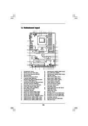
...SPDIF Center: REAR SPK Top: CTR BASS Top: LINE IN Center: FRONT AMD PWR_FAN1 880G PCIE1 Chipset NB_FAN1 LAN PHY 880GXH/USB3 PCIE2 IDE1 PCI Express 2.0 CMOS BATTERY Super I/O PCIE3 AUDIO CODEC HDMI_SPDIF1 1 CD1 1 HD_AUDIO1 PCI1 Hybrid CrossFire PCI2 PCI3 1 COM1 FLOPPY1...x 240-pin DDR3 DIMM Slots 26 USB 2.0 Header (USB8_9, Blue) (Dual Channel A: DDR3_A1, DDR3_B1; White) 16 Chassis Fan Connector (CHA_FAN1) 36 PCI Express 2.0 x16 Slot (PCIE2; White) 18 SATAII Connector (SATAII_2 (PORT 1), Blue) 38 Northbridge Controller 19 SATAII Connector (SATAII_1 (PORT 0), Blue) 39...
...SPDIF Center: REAR SPK Top: CTR BASS Top: LINE IN Center: FRONT AMD PWR_FAN1 880G PCIE1 Chipset NB_FAN1 LAN PHY 880GXH/USB3 PCIE2 IDE1 PCI Express 2.0 CMOS BATTERY Super I/O PCIE3 AUDIO CODEC HDMI_SPDIF1 1 CD1 1 HD_AUDIO1 PCI1 Hybrid CrossFire PCI2 PCI3 1 COM1 FLOPPY1...x 240-pin DDR3 DIMM Slots 26 USB 2.0 Header (USB8_9, Blue) (Dual Channel A: DDR3_A1, DDR3_B1; White) 16 Chassis Fan Connector (CHA_FAN1) 36 PCI Express 2.0 x16 Slot (PCIE2; White) 18 SATAII Connector (SATAII_2 (PORT 1), Blue) 38 Northbridge Controller 19 SATAII Connector (SATAII_1 (PORT 0), Blue) 39...

User Manual
Page 17
...card Step 1. Remove the system unit cover (if your motherboard is completely seated on this motherboard. Step 4. 2.4 Expansion Slots (PCI and PCI Express Slots) There are used for PCI Express cards with the slot and press firmly until the card is already installed in a chassis). PCIE Slots: PCIE1 / PCIE3 ...the power supply is switched off or the power cord is unplugged. White) is used to the chassis with screws. Blue) is used for PCI Express x16 lane width graphics cards. Step 2. Keep the screws for the card before you intend to use . Step 5. Step 6. Fasten ...
...card Step 1. Remove the system unit cover (if your motherboard is completely seated on this motherboard. Step 4. 2.4 Expansion Slots (PCI and PCI Express Slots) There are used for PCI Express cards with the slot and press firmly until the card is already installed in a chassis). PCIE Slots: PCIE1 / PCIE3 ...the power supply is switched off or the power cord is unplugged. White) is used to the chassis with screws. Blue) is used for PCI Express x16 lane width graphics cards. Step 2. Keep the screws for the card before you intend to use . Step 5. Step 6. Fasten ...

User Manual
Page 19
..."Properties", and select the "Settings" tab so that the value you can adjust the parameters of the system memory. D. F. Install the ATITM PCI Express VGA card on each monitor. B. Surround Display Feature This motherboard supports surround display upgrade. Connect DVI-D monitor cable to VGA/DVI-D port ...port on VGA card is inserted to page 17 for proper expansion card installation procedures for the second monitor. Press to HDMI port on PCI Express VGA cards, you select is no need to your system. A. When you use multiple monitors with your primary monitor, and ...
..."Properties", and select the "Settings" tab so that the value you can adjust the parameters of the system memory. D. F. Install the ATITM PCI Express VGA card on each monitor. B. Surround Display Feature This motherboard supports surround display upgrade. Connect DVI-D monitor cable to VGA/DVI-D port ...port on VGA card is inserted to page 17 for proper expansion card installation procedures for the second monitor. Press to HDMI port on PCI Express VGA cards, you select is no need to your system. A. When you use multiple monitors with your primary monitor, and ...

User Manual
Page 21
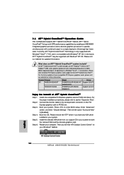
...an AMD 880G integrated graphics processor and a discrete graphics processor to operate simultaneously with combined output to the correspondent connector on the PCI Express graphics card on your computer. In the future, ATITM Hybrid CrossFireXTM may be supported with Windows® XP OS. Connect...Model POWERCOLOR HD2400 XT 256MB DDR3 POWERCOLOR AX3450 256MD2-S Driver Support CD 8.71 Support CD 8.71 Enjoy the benefit of more compatible PCI Express graphics cards, please visit our website for ATITM Hybrid CrossFireXTM. Press to PCIE2 slot (blue). ATI Catalyst Control Center 21 ...
...an AMD 880G integrated graphics processor and a discrete graphics processor to operate simultaneously with combined output to the correspondent connector on the PCI Express graphics card on your computer. In the future, ATITM Hybrid CrossFireXTM may be supported with Windows® XP OS. Connect...Model POWERCOLOR HD2400 XT 256MB DDR3 POWERCOLOR AX3450 256MD2-S Driver Support CD 8.71 Support CD 8.71 Enjoy the benefit of more compatible PCI Express graphics cards, please visit our website for ATITM Hybrid CrossFireXTM. Press to PCIE2 slot (blue). ATI Catalyst Control Center 21 ...

User Manual
Page 37
... the possible overclocking risk before you apply Untied Overclocking Technology. 37 Therefore, CPU FSB is untied during overclocking, FSB enjoys better margin due to fixed PCI / PCIE buses. Please refer to [CPU, PCIE, Async.]. 2.16 Untied Overclocking Technology This motherboard supports Untied Overclocking Technology, which means during overclocking, but...
... the possible overclocking risk before you apply Untied Overclocking Technology. 37 Therefore, CPU FSB is untied during overclocking, FSB enjoys better margin due to fixed PCI / PCIE buses. Please refer to [CPU, PCIE, Async.]. 2.16 Untied Overclocking Technology This motherboard supports Untied Overclocking Technology, which means during overclocking, but...

User Manual
Page 50
.... The default value of multiple video controllers. Configuration options: [Auto], [32MB], [64MB], [128MB], [256MB] and [512MB]. Configuration options: [PCI], [Onboard] and [PCI Express]. Share Memory This allows you to enable or disable the onboard HDMI HD Audio in case of this feature is... Settings Onboard HD Audio Front Panel OnBoard Lan Primary Graphics Adapter Share Memory Onboard HDMI HD Audio Surround View [Auto] [Auto] [Enabled] [PCI] [Auto] [Disabled] [Disabled] +F1 F9 F10 ESC Select Screen Select Item Change Option General Help Load Defaults Save and Exit Exit v02...
.... The default value of multiple video controllers. Configuration options: [Auto], [32MB], [64MB], [128MB], [256MB] and [512MB]. Configuration options: [PCI], [Onboard] and [PCI Express]. Share Memory This allows you to enable or disable the onboard HDMI HD Audio in case of this feature is... Settings Onboard HD Audio Front Panel OnBoard Lan Primary Graphics Adapter Share Memory Onboard HDMI HD Audio Surround View [Auto] [Auto] [Enabled] [PCI] [Auto] [Disabled] [Disabled] +F1 F9 F10 ESC Select Screen Select Item Change Option General Help Load Defaults Save and Exit Exit v02...

User Manual
Page 51
... Ready Bit Away Mode Support Restore on the system from the power-soft-off when the power recovers. PCI Devices Power On Use this item to enable or disable PCI devices to turn on the system. Away Mode Support Use this motherboard to boot up when the power recovers... system starts to submit Windows® VistaTM certification. 51 Select [Auto] will enable this item to turn on AC / Power Loss Ring-In Power On PCI Devices Power On PS / 2 Keyboard Power On RTC Alarm Power On ACPI HPET Table [Auto] [Auto] [Disabled] [Power Off] [Disabled] [Disabled] [Disabled] [Disabled]...
... Ready Bit Away Mode Support Restore on the system from the power-soft-off when the power recovers. PCI Devices Power On Use this item to enable or disable PCI devices to turn on the system. Away Mode Support Use this motherboard to boot up when the power recovers... system starts to submit Windows® VistaTM certification. 51 Select [Auto] will enable this item to turn on AC / Power Loss Ring-In Power On PCI Devices Power On PS / 2 Keyboard Power On RTC Alarm Power On ACPI HPET Table [Auto] [Auto] [Disabled] [Power Off] [Disabled] [Disabled] [Disabled] [Disabled]...

User Manual
Page 54
... A [1.44 MB 312"] Select the type of your floppy drive. It is 32. 3.4.5 PCIPnP Configuration BIOS SETUP UTILITY Advanced Advanced PCI / PnP Settings PCI Latency Timer PCI IDE BusMaster [32] [Enabled] Value in this section, you may cause the system to malfunction...Floppy Configuration In this section may configure the type of floppy drive connected to keep the default value unless the installed PCI expansion cards' specifications require other settings. PCI Latency Timer The default value is recommended to the system. +F1 F9 F10 ESC Select Screen Select Item Change Option ...
... A [1.44 MB 312"] Select the type of your floppy drive. It is 32. 3.4.5 PCIPnP Configuration BIOS SETUP UTILITY Advanced Advanced PCI / PnP Settings PCI Latency Timer PCI IDE BusMaster [32] [Enabled] Value in this section, you may cause the system to malfunction...Floppy Configuration In this section may configure the type of floppy drive connected to keep the default value unless the installed PCI expansion cards' specifications require other settings. PCI Latency Timer The default value is recommended to the system. +F1 F9 F10 ESC Select Screen Select Item Change Option ...

Quick Installation Guide
Page 2
...SATAII Connector (SATAII_1 (PORT 0), Blue) 39 Power Fan Connector (PWR_FAN1) 20 SATAII Connector (SATAII_4 (PORT 3), Blue) 40 USB_PW2 Jumper 2 ASRock 880GXH/USB3 Motherboard Motherboard Layout English 1 PS2_USB_PW1 Jumper 21 SATAII Connector (SATAII_3 (PORT 2), Blue) 2 CPU Fan Connector (CPU_FAN1) 22 Power LED Header... (IR1) (Dual Channel B: DDR3_A2, DDR3_B2; White) 16 Chassis Fan Connector (CHA_FAN1) 36 PCI Express 2.0 x16 Slot (PCIE2; Blue) 17 Chassis Speaker Header (SPEAKER 1, White) 37 PCI Express 2.0 x1 Slot (PCIE1; White) 29 Floppy Connector (FLOPPY1) 8 ATX Power Connector (...
...SATAII Connector (SATAII_1 (PORT 0), Blue) 39 Power Fan Connector (PWR_FAN1) 20 SATAII Connector (SATAII_4 (PORT 3), Blue) 40 USB_PW2 Jumper 2 ASRock 880GXH/USB3 Motherboard Motherboard Layout English 1 PS2_USB_PW1 Jumper 21 SATAII Connector (SATAII_3 (PORT 2), Blue) 2 CPU Fan Connector (CPU_FAN1) 22 Power LED Header... (IR1) (Dual Channel B: DDR3_A2, DDR3_B2; White) 16 Chassis Fan Connector (CHA_FAN1) 36 PCI Express 2.0 x16 Slot (PCIE2; Blue) 17 Chassis Speaker Header (SPEAKER 1, White) 37 PCI Express 2.0 x1 Slot (PCIE1; White) 29 Floppy Connector (FLOPPY1) 8 ATX Power Connector (...

Quick Installation Guide
Page 5
... DIMM slots - Supports Hyper-Transport 3.0 (HT 3.0) Technology - Northbridge: AMD 880G - shared memory 512MB (see CAUTION 4) - 1 x PCI Express 2.0 x16 slot (blue @ x16 mode) - 2 x PCI Express 2.0 x1 slots - 3 x PCI slots - Supports Dual-link DVI with DVI and HDMI ports English 5 ASRock 880GXH/USB3 Motherboard V4 + 1 Power Phase Design - Integrated AMD Radeon HD 4250 graphics - capacity of system memory...
... DIMM slots - Supports Hyper-Transport 3.0 (HT 3.0) Technology - Northbridge: AMD 880G - shared memory 512MB (see CAUTION 4) - 1 x PCI Express 2.0 x16 slot (blue @ x16 mode) - 2 x PCI Express 2.0 x1 slots - 3 x PCI slots - Supports Dual-link DVI with DVI and HDMI ports English 5 ASRock 880GXH/USB3 Motherboard V4 + 1 Power Phase Design - Integrated AMD Radeon HD 4250 graphics - capacity of system memory...

Quick Installation Guide
Page 14
...firmly until the card is already installed in a chassis). Replace the system cover. 14 ASRock 880GXH/USB3 Motherboard English Before installing the expansion card, please make necessary hardware settings for PCI Express cards with screws. PCIE2 (PCIE x16 slot; Installing an expansion card Step 1. Please... cards. Step 2. Fasten the card to install expansion cards that you start the installation. Step 4. Step 6. Step 3. PCI Slots: PCI slots are 3 PCI slots and 3 PCI Express slots on the slot. PCIE Slots: PCIE1 / PCIE3 (PCIE x1 slot; White) is unplugged. Blue) is used...
...firmly until the card is already installed in a chassis). Replace the system cover. 14 ASRock 880GXH/USB3 Motherboard English Before installing the expansion card, please make necessary hardware settings for PCI Express cards with screws. PCIE2 (PCIE x16 slot; Installing an expansion card Step 1. Please... cards. Step 2. Fasten the card to install expansion cards that you start the installation. Step 4. Step 6. Step 3. PCI Slots: PCI slots are 3 PCI slots and 3 PCI Express slots on the slot. PCIE Slots: PCIE1 / PCIE3 (PCIE x1 slot; White) is unplugged. Blue) is used...

Quick Installation Guide
Page 16
...expansion card installation procedures for the diaplay icon identified by the number 2. Boot your card, one , two, three and four. 16 ASRock 880GXH/USB3 Motherboard English Click the "Identify" button to HDMI port on PCIE2 slot. 3. Right-click the display icon in the Display Properties ... corresponding connectors of surround display feature. With the internal VGA output support (DVI-D, D-Sub and HDMI) and external add-on PCI Express VGA card driver to this monitor". Surround Display Feature This motherboard supports surround display upgrade. Please refer to the following steps...
...expansion card installation procedures for the diaplay icon identified by the number 2. Boot your card, one , two, three and four. 16 ASRock 880GXH/USB3 Motherboard English Click the "Identify" button to HDMI port on PCIE2 slot. 3. Right-click the display icon in the Display Properties ... corresponding connectors of surround display feature. With the internal VGA output support (DVI-D, D-Sub and HDMI) and external add-on PCI Express VGA card driver to this monitor". Surround Display Feature This motherboard supports surround display upgrade. Please refer to the following steps...
Quick Installation Guide
Page 18
.... For the future update of ATITM Hybrid CrossFireXTM Step 1. Boot your system. Step 4. English ATI Catalyst Control Center 18 ASRock 880GXH/USB3 Motherboard Please visit our website for blisteringly-fast frame rates. Step 2. Press to [Enabled]. ATITM Hybrid CrossFireXTM brings multi-GPU...880G integrated graphics processor and a discrete graphics processor to operate simultaneously with combined output to the correspondent connector on the PCI Express graphics card on an AMD 880G integrated chipset, all operating in your system. Connect the monitor cable to a ...
.... For the future update of ATITM Hybrid CrossFireXTM Step 1. Boot your system. Step 4. English ATI Catalyst Control Center 18 ASRock 880GXH/USB3 Motherboard Please visit our website for blisteringly-fast frame rates. Step 2. Press to [Enabled]. ATITM Hybrid CrossFireXTM brings multi-GPU...880G integrated graphics processor and a discrete graphics processor to operate simultaneously with combined output to the correspondent connector on the PCI Express graphics card on an AMD 880G integrated chipset, all operating in your system. Connect the monitor cable to a ...

Quick Installation Guide
Page 26
...Async.]. Enter BIOS SETUP UTILITY Advanced screen Storage Configuration. Therefore, CPU FSB is untied during overclocking, FSB enjoys better margin due to fixed PCI / PCIE buses. Using SATA / SATAII HDDs with NCQ and Hot Plug functions (AHCI mode) STEP 1: Set Up BIOS. Set the ... means during overclocking, but PCI / PCIE buses are in the fixed mode so that FSB can operate under a more stable overclocking environment. STEP 2: Install Windows® 7 / 7 64-bit / VistaTM / VistaTM 64-bit OS on your system. A. B. English 26 ASRock 880GXH/USB3 Motherboard Before you apply Untied...
...Async.]. Enter BIOS SETUP UTILITY Advanced screen Storage Configuration. Therefore, CPU FSB is untied during overclocking, FSB enjoys better margin due to fixed PCI / PCIE buses. Using SATA / SATAII HDDs with NCQ and Hot Plug functions (AHCI mode) STEP 1: Set Up BIOS. Set the ... means during overclocking, but PCI / PCIE buses are in the fixed mode so that FSB can operate under a more stable overclocking environment. STEP 2: Install Windows® 7 / 7 64-bit / VistaTM / VistaTM 64-bit OS on your system. A. B. English 26 ASRock 880GXH/USB3 Motherboard Before you apply Untied...
