RAID Installation Guide
Page 4
... into floppy drive A: press any key to start to configure RAID function, you need to set the RAID configuration by using the Windows RAID installation guide in this document for details. 4 When prompted, insert the SATA / SATAII driver diskette containing AMD RAID driver. Please select CD-ROM as the boot device. E. After reading the floppy disk, the driver will see the message on the screen, "Do you install Windows XP / Windows XP 64-bit on IDE HDDs and want to generate Serial ATA driver...
... into floppy drive A: press any key to start to configure RAID function, you need to set the RAID configuration by using the Windows RAID installation guide in this document for details. 4 When prompted, insert the SATA / SATAII driver diskette containing AMD RAID driver. Please select CD-ROM as the boot device. E. After reading the floppy disk, the driver will see the message on the screen, "Do you install Windows XP / Windows XP 64-bit on IDE HDDs and want to generate Serial ATA driver...
RAID Installation Guide
Page 5
... no SATA / SATAII device used, please set the RAID configuration by using the Windows RAID installation guide in our Support CD: .. \ I386 (For Windows 7 / Vista OS) .. \ AMD64 (For Windows 7 64-bit / Vista 64-bit OS) After that, please insert Windows 7 / 7 64-bit / Vista / Vista 64-bit optical disk into your optical drive, and click the "Load Driver" button on the left on the bottom to load the AMD RAID drivers. NOTE1. If you install Windows 7 / 7 64-bit / Vista / Vista 64-bit on IDE HDDs...
... no SATA / SATAII device used, please set the RAID configuration by using the Windows RAID installation guide in our Support CD: .. \ I386 (For Windows 7 / Vista OS) .. \ AMD64 (For Windows 7 64-bit / Vista 64-bit OS) After that, please insert Windows 7 / 7 64-bit / Vista / Vista 64-bit optical disk into your optical drive, and click the "Load Driver" button on the left on the bottom to load the AMD RAID drivers. NOTE1. If you install Windows 7 / 7 64-bit / Vista / Vista 64-bit on IDE HDDs...
RAID Installation Guide
Page 10
... Support On the Host PC with the AMD SB710 SATA RAID Controller (the "Host PC"). 2. Double-click the Install CD's icon to launch it . 4. Double-click the Installer icon to open it (right). Boot the PC or server, launch Windows, and log in the RAID configuration (server, controller, logical drives, physical drives, and enclosure). RAIDXpert uses this guide carefully and follow the instructions below to your CD-ROM drive...
... Support On the Host PC with the AMD SB710 SATA RAID Controller (the "Host PC"). 2. Double-click the Install CD's icon to launch it . 4. Double-click the Installer icon to open it (right). Boot the PC or server, launch Windows, and log in the RAID configuration (server, controller, logical drives, physical drives, and enclosure). RAIDXpert uses this guide carefully and follow the instructions below to your CD-ROM drive...
User Manual
Page 11
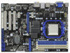
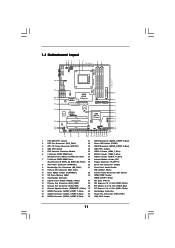
...29 Floppy Connector (FLOPPY1) 8 ATX Power Connector (ATXPWR1) 30 Serial Port Connector (COM1) 9 Northbridge Fan Connector (NB_FAN1) 31 Front Panel Audio Header 10 Primary IDE Connector (IDE1, Blue) (HD_AUDIO1, White) 11 Clear CMOS Jumper (CLRCMOS1) 32 Internal Audio Connector: CD1 (Black) 12 SPI Flash Memory (8Mb) 33 HDMI_SPDIF Header 13 Southbridge Controller (HDMI_SPDIF1, White) 14 System Panel Header (PANEL1, White) 34 PCI Slots (PCI1-3) 15 Chassis Fan Connector (CHA_FAN2) 35 PCI Express 2.0 x1 Slot (PCIE3; Blue) 17 Chassis Speaker Header (SPEAKER 1, White) 37 PCI Express...
...29 Floppy Connector (FLOPPY1) 8 ATX Power Connector (ATXPWR1) 30 Serial Port Connector (COM1) 9 Northbridge Fan Connector (NB_FAN1) 31 Front Panel Audio Header 10 Primary IDE Connector (IDE1, Blue) (HD_AUDIO1, White) 11 Clear CMOS Jumper (CLRCMOS1) 32 Internal Audio Connector: CD1 (Black) 12 SPI Flash Memory (8Mb) 33 HDMI_SPDIF Header 13 Southbridge Controller (HDMI_SPDIF1, White) 14 System Panel Header (PANEL1, White) 34 PCI Slots (PCI1-3) 15 Chassis Fan Connector (CHA_FAN2) 35 PCI Express 2.0 x1 Slot (PCIE3; Blue) 17 Chassis Speaker Header (SPEAKER 1, White) 37 PCI Express...
User Manual
Page 18
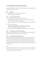
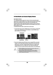
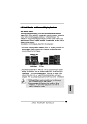
... drive same or different display contents. When you playback HDCP-protected video from our support CD to your system already, you can easily enjoy the benefits of dual monitor function after your computer. VGA/D-Sub port VGA/DVI-D port HDMI port 2. With the internal VGA output support (DVI-D, D-Sub and HDMI), you haven't installed onboard VGA driver yet, please install onboard VGA driver from our support CD to use dual monitor function on VGA card to this motherboard. 1. Connect DVI-D monitor cable to VGA/DVI-D port...
... drive same or different display contents. When you playback HDCP-protected video from our support CD to your system already, you can easily enjoy the benefits of dual monitor function after your computer. VGA/D-Sub port VGA/DVI-D port HDMI port 2. With the internal VGA output support (DVI-D, D-Sub and HDMI), you haven't installed onboard VGA driver yet, please install onboard VGA driver from our support CD to use dual monitor function on VGA card to this motherboard. 1. Connect DVI-D monitor cable to VGA/DVI-D port...

User Manual
Page 19
.... Then connect other monitor cables to HDMI port on PCIE2 slot. 3. C. Press to your primary monitor, and then select "Primary". D. Install the onboard VGA driver and the add-on each monitor. Click "Apply" or "OK" to display a large number on PCI Express VGA card driver to enter BIOS setup. Repeat steps C through E for details. 2. Click the "Identify" button to apply these new values. Surround Display Feature This motherboard supports surround display upgrade. Enter "Share Memory" option to adjust the memory capability...
.... Then connect other monitor cables to HDMI port on PCIE2 slot. 3. C. Press to your primary monitor, and then select "Primary". D. Install the onboard VGA driver and the add-on each monitor. Click "Apply" or "OK" to display a large number on PCI Express VGA card driver to enter BIOS setup. Repeat steps C through E for details. 2. Click the "Identify" button to apply these new values. Surround Display Feature This motherboard supports surround display upgrade. Enter "Share Memory" option to adjust the memory capability...
User Manual
Page 33
... 64-bit on a RAID disk composed of system boot-up, press key, and then a window for boot devices selection appears. Set the "SATA Operation Mode" option to boot your system. C. Please follow below steps. B. B. When you want to install those required drivers. Enter BIOS SETUP UTILITY Advanced screen Storage Configuration. A. E. Therefore, the drivers you will start Please insert a floppy diskette into the floppy drive, and press any key. Then you install can be auto-detected and listed on the screen, "Generate Serial ATA driver...
... 64-bit on a RAID disk composed of system boot-up, press key, and then a window for boot devices selection appears. Set the "SATA Operation Mode" option to boot your system. C. Please follow below steps. B. B. When you want to install those required drivers. Enter BIOS SETUP UTILITY Advanced screen Storage Configuration. A. E. Therefore, the drivers you will start Please insert a floppy diskette into the floppy drive, and press any key. Then you install can be auto-detected and listed on the screen, "Generate Serial ATA driver...
User Manual
Page 34
... Support CD: .. \ RAID Installation Guide STEP 4: Install Windows® XP / XP 64-bit OS on your system. After reading the floppy disk, the driver will be presented. Enter BIOS SETUP UTILITY Advanced screen Storage Configuration. Before you start to configure RAID function, you need to check the RAID installation guide in the Support CD for Windows® XP 64-bit.) NOTE. STEP 1: Set up "SATA Operation Mode" to [RAID] first. A. STEP 2: Use "RAID Installation Guide" to set up BIOS. Before you start to install Windows® XP / XP 64-bit...
... Support CD: .. \ RAID Installation Guide STEP 4: Install Windows® XP / XP 64-bit OS on your system. After reading the floppy disk, the driver will be presented. Enter BIOS SETUP UTILITY Advanced screen Storage Configuration. Before you start to configure RAID function, you need to check the RAID installation guide in the Support CD for Windows® XP 64-bit.) NOTE. STEP 1: Set up "SATA Operation Mode" to [RAID] first. A. STEP 2: Use "RAID Installation Guide" to set up BIOS. Before you start to install Windows® XP / XP 64-bit...

User Manual
Page 41
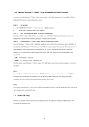
...see the option "Value (All Cores)". Processor Maximum Voltage It will display Processor Maximum Frequency for reference. BIOS SETUP UTILITY Main OC Tweaker Advanced H/W Monitor Boot Security Exit EZ Overclocking Turbo 50 [Press Enter] Load Optimized CPU OC Setting [Press Enter] Load Optimized mGPU OC Setting [Press Enter] CPU Configuration Overclock Mode CPU Frequency (MHZ) PCIE Frequency (MHz) Spread Spectrum Boot Failure Guard Boot Failure Guard Count Advanced Clock Calibration CPU Active Core Control [Auto] [200] [100] [Auto] [Enabled] [3] [Disabled] [All Cores] Processor Maximum...
...see the option "Value (All Cores)". Processor Maximum Voltage It will display Processor Maximum Frequency for reference. BIOS SETUP UTILITY Main OC Tweaker Advanced H/W Monitor Boot Security Exit EZ Overclocking Turbo 50 [Press Enter] Load Optimized CPU OC Setting [Press Enter] Load Optimized mGPU OC Setting [Press Enter] CPU Configuration Overclock Mode CPU Frequency (MHZ) PCIE Frequency (MHz) Spread Spectrum Boot Failure Guard Boot Failure Guard Count Advanced Clock Calibration CPU Active Core Control [Auto] [200] [100] [Auto] [Enabled] [3] [Disabled] [All Cores] Processor Maximum...

User Manual
Page 53
... partition and format the new IDE hard disk drives. S.M.A.R.T. This is enabled, it will enhance hard disk performance by optimizing the hard disk timing. LBA/Large Mode Use this item is used for IDE CD/DVD drives. [ARMD]: This is [Auto]. Configuration options: [Not Installed], [Auto], [CD/DVD], and [ARMD]. [Not Installed]: Select [Not Installed] to disable the use a disk utility, such as FDISK, to active. [CD/DVD]:This is used for IDE ARMD (ATAPI Removable Media Device), such as MO. for compatible IDE devices.
... partition and format the new IDE hard disk drives. S.M.A.R.T. This is enabled, it will enhance hard disk performance by optimizing the hard disk timing. LBA/Large Mode Use this item is used for IDE CD/DVD drives. [ARMD]: This is [Auto]. Configuration options: [Not Installed], [Auto], [CD/DVD], and [ARMD]. [Not Installed]: Select [Not Installed] to disable the use a disk utility, such as FDISK, to active. [CD/DVD]:This is used for IDE ARMD (ATAPI Removable Media Device), such as MO. for compatible IDE devices.

User Manual
Page 55
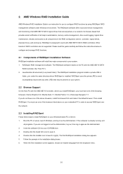
... item to set the PS/2 port type. 55 Configuration options: [Disabled], [3F8 / IRQ4], [2F8 / IRQ3], [3E8 / IRQ4], [2E8 / IRQ3]. 3.4.7 Super IO Configuration BIOS SETUP UTILITY Advanced Configure Super IO Chipset OnBoard Floppy Controller Serial Port Address Infrared Port Address PS/2 Port Type [Enabled] [3F8 / IRQ4] [Disabled] [Auto] Allow BIOS to set the address for the onboard infrared port or disable it . PS/2 Port Type Use this item to Enable or Disable Floppy Controller. +F1 F9 F10 ESC Select Screen Select Item Change Option General Help Load Defaults Save and Exit...
... item to set the PS/2 port type. 55 Configuration options: [Disabled], [3F8 / IRQ4], [2F8 / IRQ3], [3E8 / IRQ4], [2E8 / IRQ3]. 3.4.7 Super IO Configuration BIOS SETUP UTILITY Advanced Configure Super IO Chipset OnBoard Floppy Controller Serial Port Address Infrared Port Address PS/2 Port Type [Enabled] [3F8 / IRQ4] [Disabled] [Auto] Allow BIOS to set the address for the onboard infrared port or disable it . PS/2 Port Type Use this item to Enable or Disable Floppy Controller. +F1 F9 F10 ESC Select Screen Select Item Change Option General Help Load Defaults Save and Exit...

User Manual
Page 56
... not allowed to enable or disable the use only under legacy OS and BIOS setup when [Disabled] is selected. Please refer to use of these four options: [Enabled] - USB devices are four configuration options: [Enabled], [Auto], [Disabled] and [BIOS Setup Only]. 3.4.8 USB Configuration BIOS SETUP UTILITY Advanced USB Configuration USB Controller USB 2.0 Support Legacy USB Support USB 3.0 Controller [Enabled] [Enabled] [Enabled] [Enabled] To enable or disable the onboard USB controllers. +F1 F9 F10 ESC Select Screen Select Item Change Option General Help Load Defaults Save and...
... not allowed to enable or disable the use only under legacy OS and BIOS setup when [Disabled] is selected. Please refer to use of these four options: [Enabled] - USB devices are four configuration options: [Enabled], [Auto], [Disabled] and [BIOS Setup Only]. 3.4.8 USB Configuration BIOS SETUP UTILITY Advanced USB Configuration USB Controller USB 2.0 Support Legacy USB Support USB 3.0 Controller [Enabled] [Enabled] [Enabled] [Enabled] To enable or disable the onboard USB controllers. +F1 F9 F10 ESC Select Screen Select Item Change Option General Help Load Defaults Save and...
User Manual
Page 59
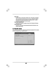
Boot Logo Use this item to enable or disable the Boot From Onboard LAN feature. Currently, the option [Auto] is set or change the supervisor/user password for the system. Boot From Onboard LAN Use this option to select logo in POST screen. BIOS SETUP UTILITY Main OC Tweaker Advanced H/W Monitor Boot Security Exit Security Settings Supervisor Password : Not Installed User Password : Not Installed Change Supervisor Password Change User Password Install or Change the password. Select Screen Select Item Enter Change F1 General Help F9 Load Defaults F10 Save and Exit ESC Exit v02.54 ...
Boot Logo Use this item to enable or disable the Boot From Onboard LAN feature. Currently, the option [Auto] is set or change the supervisor/user password for the system. Boot From Onboard LAN Use this option to select logo in POST screen. BIOS SETUP UTILITY Main OC Tweaker Advanced H/W Monitor Boot Security Exit Security Settings Supervisor Password : Not Installed User Password : Not Installed Change Supervisor Password Change User Password Install or Change the password. Select Screen Select Item Enter Change F1 General Help F9 Load Defaults F10 Save and Exit ESC Exit v02.54 ...
User Manual
Page 61
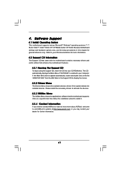
...-bit. The CD automatically displays the Main Menu if "AUTORUN" is enabled in your CD-ROM drive. Click on the file "ASSETUP.EXE" from the BIN folder in this chapter for more about ASRock, welcome to your OS documentation for general reference only. 4. Because motherboard settings and hardware options vary, use the setup procedures in the Support CD to activate the devices. 4.2.3 Utilities Menu The Utilities Menu shows the applications software...
...-bit. The CD automatically displays the Main Menu if "AUTORUN" is enabled in your CD-ROM drive. Click on the file "ASSETUP.EXE" from the BIN folder in this chapter for more about ASRock, welcome to your OS documentation for general reference only. 4. Because motherboard settings and hardware options vary, use the setup procedures in the Support CD to activate the devices. 4.2.3 Utilities Menu The Utilities Menu shows the applications software...

Quick Installation Guide
Page 2
...SATAII Connector (SATAII_5 (PORT 4), Blue) 4 AM3 CPU Socket 24 USB_PW1 Jumper 5 CPU Heatsink Retention Module 25 USB 2.0 Header (USB6_7, Blue) 6 2 x 240-pin DDR3 DIMM Slots 26 USB 2.0 Header (USB8_9, Blue) (Dual Channel A: DDR3_A1, DDR3_B1; Blue) 17 Chassis Speaker Header (SPEAKER 1, White) 37 PCI Express 2.0 x1 Slot (PCIE1; White) 18 SATAII Connector (SATAII_2 (PORT 1), Blue) 38 Northbridge Controller 19 SATAII Connector (SATAII_1 (PORT 0), Blue) 39 Power Fan Connector (PWR_FAN1) 20 SATAII Connector (SATAII_4 (PORT 3), Blue) 40 USB_PW2 Jumper 2 ASRock 880GXH/USB3 Motherboard
...SATAII Connector (SATAII_5 (PORT 4), Blue) 4 AM3 CPU Socket 24 USB_PW1 Jumper 5 CPU Heatsink Retention Module 25 USB 2.0 Header (USB6_7, Blue) 6 2 x 240-pin DDR3 DIMM Slots 26 USB 2.0 Header (USB8_9, Blue) (Dual Channel A: DDR3_A1, DDR3_B1; Blue) 17 Chassis Speaker Header (SPEAKER 1, White) 37 PCI Express 2.0 x1 Slot (PCIE1; White) 18 SATAII Connector (SATAII_2 (PORT 1), Blue) 38 Northbridge Controller 19 SATAII Connector (SATAII_1 (PORT 0), Blue) 39 Power Fan Connector (PWR_FAN1) 20 SATAII Connector (SATAII_4 (PORT 3), Blue) 40 USB_PW2 Jumper 2 ASRock 880GXH/USB3 Motherboard

Quick Installation Guide
Page 8
... this motherboard supports 2-channel, 4-channel, 6-channel, and 8-channel modes. ASRock website: http://www.asrock.com 9. The voltage regulator can also connect SATA hard disk to change. ASRock website: http://www.asrock.com 8 ASRock 880GXH/USB3 Motherboard English This motherboard supports Dual Channel Memory Technology. Please check AMD website for details. 2. For audio output, this motherboard supports both stereo and mono modes. To use Intelligent Energy Saver function, please enable Cool 'n' Quiet option in the BIOS setup in the support CD to adjust your hardware devices...
... this motherboard supports 2-channel, 4-channel, 6-channel, and 8-channel modes. ASRock website: http://www.asrock.com 9. The voltage regulator can also connect SATA hard disk to change. ASRock website: http://www.asrock.com 8 ASRock 880GXH/USB3 Motherboard English This motherboard supports Dual Channel Memory Technology. Please check AMD website for details. 2. For audio output, this motherboard supports both stereo and mono modes. To use Intelligent Energy Saver function, please enable Cool 'n' Quiet option in the BIOS setup in the support CD to adjust your hardware devices...

Quick Installation Guide
Page 9
... the user to define the power consumption for more details. 9 ASRock 880GXH/USB3 Motherboard English OC DNA, an exclusive utility developed by European Union to record the OC settings and share with your BIOS only in a few clicks without entering operating systems first like MS-DOS or Windows®. According to Intel's suggestion, the EuP ready power supply must use FAT32/16/12 file system...
... the user to define the power consumption for more details. 9 ASRock 880GXH/USB3 Motherboard English OC DNA, an exclusive utility developed by European Union to record the OC settings and share with your BIOS only in a few clicks without entering operating systems first like MS-DOS or Windows®. According to Intel's suggestion, the EuP ready power supply must use FAT32/16/12 file system...
Quick Installation Guide
Page 15
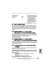
... be disabled. 2. When one of dual monitor feature without installing any add-on this motherboard. Connect DVI-D monitor cable to VGA/DVI-D port on the I/O panel, connect D-Sub monitor cable to VGA/D-Sub port on the I /O panel, or connect HDMI monitor cable to support dual VGA output so that DVI-D, D-sub and HDMI can freely enjoy the benefits of both monitors. 15 ASRock 880GXH/USB3 Motherboard English VGA/D-Sub port VGA/DVI-D port HDMI port 2. Then you haven't installed onboard VGA driver yet, please install onboard VGA driver from Blu-ray (BD) or HD-DVD...
... be disabled. 2. When one of dual monitor feature without installing any add-on this motherboard. Connect DVI-D monitor cable to VGA/DVI-D port on the I/O panel, connect D-Sub monitor cable to VGA/D-Sub port on the I /O panel, or connect HDMI monitor cable to support dual VGA output so that DVI-D, D-sub and HDMI can freely enjoy the benefits of both monitors. 15 ASRock 880GXH/USB3 Motherboard English VGA/D-Sub port VGA/DVI-D port HDMI port 2. Then you haven't installed onboard VGA driver yet, please install onboard VGA driver from Blu-ray (BD) or HD-DVD...
Quick Installation Guide
Page 25
... / SATAII HDDs without RAID functions, please follow below steps. Enter BIOS SETUP UTILITY Advanced screen Storage Configuration. HDMI_SPDIF Header (2-pin HDMI_SPDIF1) (see p.2 No. 33) HDMI_SPDIF header, providing SPDIF audio output to HDMI VGA card, allows the system to [IDE]. B. Therefore, the drivers you install can be auto-detected and listed on your optical drive first. Please connect the HDMI_SPDIF connector of HDMI VGA card to this header. 2.9 Driver Installation Guide To install the drivers to your system. 25 ASRock 880GXH/USB3 Motherboard Then, the drivers compatible to...
... / SATAII HDDs without RAID functions, please follow below steps. Enter BIOS SETUP UTILITY Advanced screen Storage Configuration. HDMI_SPDIF Header (2-pin HDMI_SPDIF1) (see p.2 No. 33) HDMI_SPDIF header, providing SPDIF audio output to HDMI VGA card, allows the system to [IDE]. B. Therefore, the drivers you install can be auto-detected and listed on your optical drive first. Please connect the HDMI_SPDIF connector of HDMI VGA card to this header. 2.9 Driver Installation Guide To install the drivers to your system. 25 ASRock 880GXH/USB3 Motherboard Then, the drivers compatible to...
Quick Installation Guide
Page 27
If you start up the computer, please press during the Power-On-Self-Test (POST) to enter BIOS Setup utility; It is a menu-driven program, which allows you to select among the predetermined choices. For the detailed information about BIOS Setup, please refer to display the menus. 27 ASRock 880GXH/USB3 Motherboard English To begin using the Support CD, insert the CD into your computer. The Support CD that...
If you start up the computer, please press during the Power-On-Self-Test (POST) to enter BIOS Setup utility; It is a menu-driven program, which allows you to select among the predetermined choices. For the detailed information about BIOS Setup, please refer to display the menus. 27 ASRock 880GXH/USB3 Motherboard English To begin using the Support CD, insert the CD into your computer. The Support CD that...


