
User Manual
Page 3
... 1.4 I/O Panel 12 2 . Installation 13 Pre-installation Precautions 13 2.1 CPU Installation 14 2.2 Installation of CPU Fan and Heatsink 14 2.3 Installation of Memory Modules (DIMM 15 2.4 Expansion Slots (PCI and PCI Express Slots 16 2.5 Dual Monitor and Surround Display Features 17 2.6 ATITM Hybrid CrossFireXTM Operation Guide 20 2.7 Jumpers Setup 22 2.8 Onboard Headers and Connectors...
... 1.4 I/O Panel 12 2 . Installation 13 Pre-installation Precautions 13 2.1 CPU Installation 14 2.2 Installation of CPU Fan and Heatsink 14 2.3 Installation of Memory Modules (DIMM 15 2.4 Expansion Slots (PCI and PCI Express Slots 16 2.5 Dual Monitor and Surround Display Features 17 2.6 ATITM Hybrid CrossFireXTM Operation Guide 20 2.7 Jumpers Setup 22 2.8 Onboard Headers and Connectors...
User Manual
Page 7
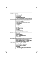
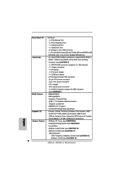
..." functions (see CAUTION 13) 7 Intelligent Energy Saver (see CAUTION 11) - ASRock OC DNA (see CAUTION 9) - Hybrid Booster: - ASRock U-COP (see CAUTION 6) - 1 x ATA133 IDE connector (supports 2 x IDE devices) - 1 x Floppy connector - 1 x IR header - 1 x Print port header - 1 x COM port header - Rear Panel I/O Connector BIOS Feature Support CD Unique Feature I/O Panel - 1 x PS/2 Mouse Port - 1 x PS/2 Keyboard Port - 1 x VGA/D-Sub Port - 1 x VGA...
..." functions (see CAUTION 13) 7 Intelligent Energy Saver (see CAUTION 11) - ASRock OC DNA (see CAUTION 9) - Hybrid Booster: - ASRock U-COP (see CAUTION 6) - 1 x ATA133 IDE connector (supports 2 x IDE devices) - 1 x Floppy connector - 1 x IR header - 1 x Print port header - 1 x COM port header - Rear Panel I/O Connector BIOS Feature Support CD Unique Feature I/O Panel - 1 x PS/2 Mouse Port - 1 x PS/2 Keyboard Port - 1 x VGA/D-Sub Port - 1 x VGA...
User Manual
Page 11
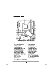
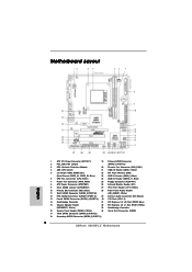
... Slot (PCIE1; Blue) 23 USB 2.0 Header (USB8_9, Blue) 6 CPU Fan Connector (CPU_FAN1) 24 USB 2.0 Header (USB10_11, Blue) 7 Power Fan Connector (PWR_FAN1) 25 Floppy Connector (FLOPPY1) 8 ATX Power Connector (ATXPWR1) 26 Infrared Module Header (IR1) 9 Clear CMOS Jumper (CLRCMOS1) 27 ...CD1 1 HD_AUDIO1 LPT1 1 PCIE1 AMD 880G Chipset Hybrid CrossFire PCIE2 880GM-LE IDE1 PWR_FAN1 SATAII_4 SATAII_5 SATAII_6 (PORT 3) (PORT 4) (PORT 5) RoHS PCI1 IR1 1 FLOPPY1 PCI2 USB10_11 1 AMD SB710 Chipset SPEAKER1 1 PLED PWRBTN PANEL 1 1 HDLED RESET 8Mb BIOS USB8_9 1 CHA_FAN1 USB6_7 1 SATAII_1 ...
... Slot (PCIE1; Blue) 23 USB 2.0 Header (USB8_9, Blue) 6 CPU Fan Connector (CPU_FAN1) 24 USB 2.0 Header (USB10_11, Blue) 7 Power Fan Connector (PWR_FAN1) 25 Floppy Connector (FLOPPY1) 8 ATX Power Connector (ATXPWR1) 26 Infrared Module Header (IR1) 9 Clear CMOS Jumper (CLRCMOS1) 27 ...CD1 1 HD_AUDIO1 LPT1 1 PCIE1 AMD 880G Chipset Hybrid CrossFire PCIE2 880GM-LE IDE1 PWR_FAN1 SATAII_4 SATAII_5 SATAII_6 (PORT 3) (PORT 4) (PORT 5) RoHS PCI1 IR1 1 FLOPPY1 PCI2 USB10_11 1 AMD SB710 Chipset SPEAKER1 1 PLED PWRBTN PANEL 1 1 HDLED RESET 8Mb BIOS USB8_9 1 CHA_FAN1 USB6_7 1 SATAII_1 ...

User Manual
Page 17
... card, you can start to this motherboard. VGA/D-Sub port VGA/DVI-D port 2. Install the ATITM PCI Express VGA card on the I /O panel. Connect the DVI-D monitor cable to the VGA/D-Sub port on this motherboard. 2.5 Dual Monitor and Surround Display Features Dual Monitor Feature This motherboard... monitor cable and D-Sub monitor cable to the VGA/DVI-D port on PCIE2 slot. 17 Connect the DVI-D monitor cable to the corresponding connectors of both monitors. And connect the D-Sub monitor cable to page 16 for proper expansion card installation procedures for DVI-D and D-Sub to ...
... card, you can start to this motherboard. VGA/D-Sub port VGA/DVI-D port 2. Install the ATITM PCI Express VGA card on the I /O panel. Connect the DVI-D monitor cable to the VGA/D-Sub port on this motherboard. 2.5 Dual Monitor and Surround Display Features Dual Monitor Feature This motherboard... monitor cable and D-Sub monitor cable to the VGA/DVI-D port on PCIE2 slot. 17 Connect the DVI-D monitor cable to the corresponding connectors of both monitors. And connect the D-Sub monitor cable to page 16 for proper expansion card installation procedures for DVI-D and D-Sub to ...
User Manual
Page 24
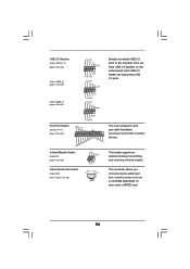
... you to receive stereo audio input from sound sources such as a CD-ROM, DVD-ROM, TV tuner card, or MPEG card. 24 Internal Audio Connectors (4-pin CD1) (CD1: see p.11 No. 26) IRTX +5V DUMMY 1 GND IRRX This header supports an optional wireless transmitting and receiving infrared module. Each USB 2.0 .... 27) USB_PWR P-11 P+11 GND DUMMY 1 GND P+10 P-10 USB_PWR USB_PWR P-9 P+9 GND DUMMY 1 GND P+8 P-8 USB_PWR USB_PWR P-7 P+7 GND DUMMY Besides six default USB 2.0 ports on the I/O panel, there are three USB 2.0 headers on this motherboard.
... you to receive stereo audio input from sound sources such as a CD-ROM, DVD-ROM, TV tuner card, or MPEG card. 24 Internal Audio Connectors (4-pin CD1) (CD1: see p.11 No. 26) IRTX +5V DUMMY 1 GND IRRX This header supports an optional wireless transmitting and receiving infrared module. Each USB 2.0 .... 27) USB_PWR P-11 P+11 GND DUMMY 1 GND P+10 P-10 USB_PWR USB_PWR P-9 P+9 GND DUMMY 1 GND P+8 P-8 USB_PWR USB_PWR P-7 P+7 GND DUMMY Besides six default USB 2.0 ports on the I/O panel, there are three USB 2.0 headers on this motherboard.
User Manual
Page 25
...taskbar to function correctly. Connect Mic_IN (MIC) to Ground (GND). For Windows® XP / XP 64-bit OS: Click "Audio I/O", select "Connector Settings" , choose "Disable front panel jack detection", and save the change by clicking "OK". G. To activate the front mic. C. Connect Ground (GND) to MIC2_L. E. For Windows...Settings, and then select Chipset Configuration. If you want to make the Front Mic as below: A. MIC_RET and OUT_RET are for AC'97 audio panel. For Windows® 7 / 7 64-bit / VistaTM / VistaTM 64-bit OS: Go to the "Front Mic" Tab in our ...
...taskbar to function correctly. Connect Mic_IN (MIC) to Ground (GND). For Windows® XP / XP 64-bit OS: Click "Audio I/O", select "Connector Settings" , choose "Disable front panel jack detection", and save the change by clicking "OK". G. To activate the front mic. C. Connect Ground (GND) to MIC2_L. E. For Windows...Settings, and then select Chipset Configuration. If you want to make the Front Mic as below: A. MIC_RET and OUT_RET are for AC'97 audio panel. For Windows® 7 / 7 64-bit / VistaTM / VistaTM 64-bit OS: Go to the "Front Mic" Tab in our ...
Quick Installation Guide
Page 2
...) 33 Northbridge Controller 16 System Panel Header (PANEL1, White) 34 Serial Port Connector (COM1) 17 Third SATAII Connector (SATAII_3 (PORT 2)) 18 Secondary SATAII Connector (SATAII_2 (PORT 1)) 2 ASRock 880GM-LE Motherboard Blue) 23 USB 2.0 Header (USB8_9, Blue) 6 CPU Fan Connector (CPU_FAN1) 24 USB 2.0 Header (USB10_11, Blue) 7 Power Fan Connector (PWR_FAN1) 25 Floppy Connector (FLOPPY1) 8 ATX Power Connector (ATXPWR1) 26 Infrared Module Header...
...) 33 Northbridge Controller 16 System Panel Header (PANEL1, White) 34 Serial Port Connector (COM1) 17 Third SATAII Connector (SATAII_3 (PORT 2)) 18 Secondary SATAII Connector (SATAII_2 (PORT 1)) 2 ASRock 880GM-LE Motherboard Blue) 23 USB 2.0 Header (USB8_9, Blue) 6 CPU Fan Connector (CPU_FAN1) 24 USB 2.0 Header (USB10_11, Blue) 7 Power Fan Connector (PWR_FAN1) 25 Floppy Connector (FLOPPY1) 8 ATX Power Connector (ATXPWR1) 26 Infrared Module Header...
Quick Installation Guide
Page 6
..., AHCI and "Hot Plug" functions (see CAUTION 9) - Front panel audio connector - 3 x USB 2.0 headers (support 6 USB 2.0 ports) (see CAUTION 10) - ASRock Instant Flash (see CAUTION 7) BIOS Feature - 8Mb AMI BIOS - ASRock U-COP (see CAUTION 8) - Supports "Plug and Play" - SMBIOS 2.3.1 Support - ASRock OC Tuner (see CAUTION 13) 6 ASRock 880GM-LE Motherboard ASRock OC DNA (see CAUTION 12) - Hybrid Booster: - ACPI 1.1 Compliance...
..., AHCI and "Hot Plug" functions (see CAUTION 9) - Front panel audio connector - 3 x USB 2.0 headers (support 6 USB 2.0 ports) (see CAUTION 10) - ASRock Instant Flash (see CAUTION 7) BIOS Feature - 8Mb AMI BIOS - ASRock U-COP (see CAUTION 8) - Supports "Plug and Play" - SMBIOS 2.3.1 Support - ASRock OC Tuner (see CAUTION 13) 6 ASRock 880GM-LE Motherboard ASRock OC DNA (see CAUTION 12) - Hybrid Booster: - ACPI 1.1 Compliance...

Quick Installation Guide
Page 13
... our support CD to the VGA/DVI-D port on the I /O panel. Please refer to the following steps to page 12 for proper expansion card installation procedures for DVI-D and D-Sub to the corresponding connectors of surround display feature. And connect the D-Sub monitor cable to your... system boots. If you playback HDCP-protected video from our support CD to the VGA/D-Sub port on PCIE2 slot. 13 ASRock 880GM-LE Motherboard English Install the ATITM PCI Express VGA card on the I /O panel....
... our support CD to the VGA/DVI-D port on the I /O panel. Please refer to the following steps to page 12 for proper expansion card installation procedures for DVI-D and D-Sub to the corresponding connectors of surround display feature. And connect the D-Sub monitor cable to your... system boots. If you playback HDCP-protected video from our support CD to the VGA/D-Sub port on PCIE2 slot. 13 ASRock 880GM-LE Motherboard English Install the ATITM PCI Express VGA card on the I /O panel....

Quick Installation Guide
Page 20
Each USB 2.0 header can support two USB 2.0 ports. English 20 ASRock 880GM-LE Motherboard This header supports an optional wireless transmitting and receiving infrared module. This connector allows you to receive stereo audio input from sound sources such as a CD-ROM, DVD-ROM, TV tuner ...25-pin LPT1) (see p.2 No. 27) Infrared Module Header (5-pin IR1) (see p.2 No. 26) Internal Audio Connectors (4-pin CD1) (CD1: see p.2 No. 21) Besides six default USB 2.0 ports on the I/O panel, there are three USB 2.0 headers on this motherboard. USB 2.0 Headers (9-pin USB10_11) (see p.2 No. 24) ...
Each USB 2.0 header can support two USB 2.0 ports. English 20 ASRock 880GM-LE Motherboard This header supports an optional wireless transmitting and receiving infrared module. This connector allows you to receive stereo audio input from sound sources such as a CD-ROM, DVD-ROM, TV tuner ...25-pin LPT1) (see p.2 No. 27) Infrared Module Header (5-pin IR1) (see p.2 No. 26) Internal Audio Connectors (4-pin CD1) (CD1: see p.2 No. 21) Besides six default USB 2.0 ports on the I/O panel, there are three USB 2.0 headers on this motherboard. USB 2.0 Headers (9-pin USB10_11) (see p.2 No. 24) ...
Quick Installation Guide
Page 21
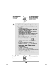
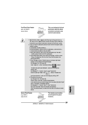
...bit OS: Click "Audio I/O", select "Connector Settings" , choose "Disable front panel jack detection", and save the change by clicking "OK". If you use AC'97 audio panel, please install it to connect them for the front panel audio cable that allows convenient connection and ...PANEL1) (see p.2, No. 28) This is an interface for AC'97 audio panel. Front Panel Audio Header (9-pin HD_AUDIO1) (see p.2 No. 16) This header accommodates several system front panel functions. 21 ASRock 880GM-LE Motherboard English Connect Ground (GND) to MIC2_L. E. F. Enter Windows system. Connect ...
...bit OS: Click "Audio I/O", select "Connector Settings" , choose "Disable front panel jack detection", and save the change by clicking "OK". If you use AC'97 audio panel, please install it to connect them for the front panel audio cable that allows convenient connection and ...PANEL1) (see p.2, No. 28) This is an interface for AC'97 audio panel. Front Panel Audio Header (9-pin HD_AUDIO1) (see p.2 No. 16) This header accommodates several system front panel functions. 21 ASRock 880GM-LE Motherboard English Connect Ground (GND) to MIC2_L. E. F. Enter Windows system. Connect ...

