
RAID Installation Guide
Page 2
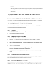
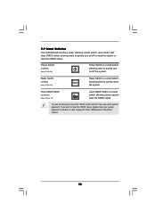
...Block Striping with Distributed Parity) RAID 5 stripes data and distributes parity information across multiple drives and duplicated on another set of the same model and capacity when creating a RAID set the option to RAID mode by providing parity data. RAID 10 (Stripe Mirroring) RAID 0 drives can be mirrored... support CD or "Quick Installation Guide", then you make a SATA / SATAII / SATA3 driver diskette, press or to enter BIOS setup to set . In the event of a single disk alone while the two hard disks perform the same work as fault tolerance by following the detailed instruction...
...Block Striping with Distributed Parity) RAID 5 stripes data and distributes parity information across multiple drives and duplicated on another set of the same model and capacity when creating a RAID set the option to RAID mode by providing parity data. RAID 10 (Stripe Mirroring) RAID 0 drives can be mirrored... support CD or "Quick Installation Guide", then you make a SATA / SATAII / SATA3 driver diskette, press or to enter BIOS setup to set . In the event of a single disk alone while the two hard disks perform the same work as fault tolerance by following the detailed instruction...

RAID Installation Guide
Page 3
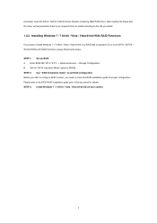
...individual physical drives the same as RAID Ready. 1.2 RAID Configurations Precautions 1. However, you set up your hard disks before you can accommodate up to create a RAID 1 (mirroring) array for this RAID 0 set is added together. For example, if one drive is full, the data is recommended ...AMD SB850 controller offers the added feature of concatenation, where the capacity of other hard disk has 60GB, the maximum storage capacity for the RAID 1 set is 120GB. 2. If you are creating a RAID 0 (striping) array for each drive. For example, if one physical drive. RAID 5 ...
...individual physical drives the same as RAID Ready. 1.2 RAID Configurations Precautions 1. However, you set up your hard disks before you can accommodate up to create a RAID 1 (mirroring) array for this RAID 0 set is added together. For example, if one drive is full, the data is recommended ...AMD SB850 controller offers the added feature of concatenation, where the capacity of other hard disk has 60GB, the maximum storage capacity for the RAID 1 set is 120GB. 2. If you are creating a RAID 0 (striping) array for each drive. For example, if one physical drive. RAID 5 ...
RAID Installation Guide
Page 4
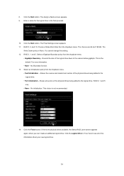
...system boot-up BIOS. Before you can start to "Clear Disk Data" or not. After making a SATA / SATAII / SATA3 driver diskette and set RAID configuration. STEP 1: Set up , press key, and then a window for proper configuration. During POST at the beginning of 2 or more SATA / SATAII / SATA3 ... message on the screen, "Do you want to format the floppy diskette and copy SATA / SATAII / SATA3 drivers into your system. Insert the ASRock Support CD into the floppy diskette. C. WARNING!! Please backup your data first before you create RAID, the system will start to install Windows7 /...
...system boot-up BIOS. Before you can start to "Clear Disk Data" or not. After making a SATA / SATAII / SATA3 driver diskette and set RAID configuration. STEP 1: Set up , press key, and then a window for proper configuration. During POST at the beginning of 2 or more SATA / SATAII / SATA3 ... message on the screen, "Do you want to format the floppy diskette and copy SATA / SATAII / SATA3 drivers into your system. Insert the ASRock Support CD into the floppy diskette. C. WARNING!! Please backup your data first before you create RAID, the system will start to install Windows7 /...
RAID Installation Guide
Page 5
... 7 / 7 64-bit / Vista / Vista 64-bit OS on a RAID disk composed of 2 or more SATA / SATAII / SATA3 HDDs with RAID functions, please follow below steps. Set the "SATA Operation Mode" option to...
... 7 / 7 64-bit / Vista / Vista 64-bit OS on a RAID disk composed of 2 or more SATA / SATAII / SATA3 HDDs with RAID functions, please follow below steps. Set the "SATA Operation Mode" option to...
RAID Installation Guide
Page 6
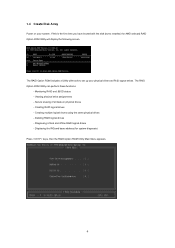
If this is the first time you have booted with tools to set up your system. Monitoring RAID and JBOD status - Deleting RAID logical drives - The RAID Option ROM includes a Utility with the disk drives installed, the AMD ...
If this is the first time you have booted with tools to set up your system. Monitoring RAID and JBOD status - Deleting RAID logical drives - The RAID Option ROM includes a Utility with the disk drives installed, the AMD ...
RAID Installation Guide
Page 16
... a Name screen appears. 9. Select an Initialization policy from the dropdown menu. • Fast Initialization - The Final Settings screen appears. 11. RAID 0, 5, and 10. The Write Cache policy is not recommended. 14. You cannot change this setting. 12. This is the default. For more information. • None - Erases the reserve and master boot...
... a Name screen appears. 9. Select an Initialization policy from the dropdown menu. • Fast Initialization - The Final Settings screen appears. 11. RAID 0, 5, and 10. The Write Cache policy is not recommended. 14. You cannot change this setting. 12. This is the default. For more information. • None - Erases the reserve and master boot...
User Manual
Page 4
... Configuration 52 3.4.4 Storage Configuration 53 3.4.5 PCIPnP Configuration 55 3.4.6 Super IO Configuration 56 3.4.7 USB Configuration 57 3.5 Hardware Health Event Monitoring Screen 58 3.6 Boot Screen 59 3.6.1 Boot Settings Configuration 59 3.7 Security Screen 60 3.8 Exit Screen 61 4 . Software Support 62 4.1 Install Operating System 62 4.2 Support CD Information 62 4.2.1 Running Support CD 62 4.2.2 Drivers Menu...
... Configuration 52 3.4.4 Storage Configuration 53 3.4.5 PCIPnP Configuration 55 3.4.6 Super IO Configuration 56 3.4.7 USB Configuration 57 3.5 Hardware Health Event Monitoring Screen 58 3.6 Boot Screen 59 3.6.1 Boot Settings Configuration 59 3.7 Security Screen 60 3.8 Exit Screen 61 4 . Software Support 62 4.1 Install Operating System 62 4.2 Support CD Information 62 4.2.1 Running Support CD 62 4.2.2 Drivers Menu...
User Manual
Page 8
... ready power supply is a certain risk involved with overclocking, including adjusting the setting in the BIOS, applying Untied Overclocking Technology, or using the thirdparty overclocking tools. CPU Frequency Stepless Control (see CAUTION 10) - CPU/Chassis Fan Multi-Speed Control - CPU Temperature Sensing Monitor - Chassis Temperature Sensing - ASRock OC DNA (see CAUTION 11) -
... ready power supply is a certain risk involved with overclocking, including adjusting the setting in the BIOS, applying Untied Overclocking Technology, or using the thirdparty overclocking tools. CPU Frequency Stepless Control (see CAUTION 10) - CPU/Chassis Fan Multi-Speed Control - CPU Temperature Sensing Monitor - Chassis Temperature Sensing - ASRock OC DNA (see CAUTION 11) -
User Manual
Page 10
... OC DNA, you can save the new BIOS file to access ASRock Instant Flash. While CPU overheat is not recommended to record the OC settings and share with others. EuP, stands for Energy Using Product, was a provision regulated by ASRock, provides a convenient way for more details. 10 For EuP ready... power supply selection, we recommend you to get the same OC settings as a profile and share with the power supply manufacturer for the user to...
... OC DNA, you can save the new BIOS file to access ASRock Instant Flash. While CPU overheat is not recommended to record the OC settings and share with others. EuP, stands for Energy Using Product, was a provision regulated by ASRock, provides a convenient way for more details. 10 For EuP ready... power supply selection, we recommend you to get the same OC settings as a profile and share with the power supply manufacturer for the user to...
User Manual
Page 13
... use a grounded wrist strap or touch a safety grounded object before you install the motherboard, study the configuration of the following precautions before touching any motherboard settings. Also remember to static electricity, NEVER place your chassis to the chassis, please do not over-tighten the screws! Doing so may cause severe damage...
... use a grounded wrist strap or touch a safety grounded object before you install the motherboard, study the configuration of the following precautions before touching any motherboard settings. Also remember to static electricity, NEVER place your chassis to the chassis, please do not over-tighten the screws! Doing so may cause severe damage...
User Manual
Page 15
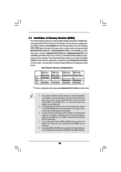
... motherboard and DIMM may refer to activate the Dual Channel Memory Technology. 3. If you to install them either in the set of blue slots (DDR3_A1 and DDR3_B1), or in the set of memory modules in all four slots. You may be activated. If only one memory module or three memory modules are...
... motherboard and DIMM may refer to activate the Dual Channel Memory Technology. 3. If you to install them either in the set of blue slots (DDR3_A1 and DDR3_B1), or in the set of memory modules in all four slots. You may be activated. If only one memory module or three memory modules are...
User Manual
Page 17
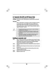
... and make sure that you start the installation. Blue) is unplugged. PCIE2 / PCIE4 (PCIE x16 slot; Before installing the expansion card, please make necessary hardware settings for PCI Express x16 lane width graphics cards, or used to install PCI Express graphics cards to motherboard chassis fan connector (CHA_FAN1, CHA_FAN2 or CHA_FAN3...
... and make sure that you start the installation. Blue) is unplugged. PCIE2 / PCIE4 (PCIE x16 slot; Before installing the expansion card, please make necessary hardware settings for PCI Express x16 lane width graphics cards, or used to install PCI Express graphics cards to motherboard chassis fan connector (CHA_FAN1, CHA_FAN2 or CHA_FAN3...
User Manual
Page 23
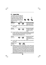
...power supply. When you to clear the data in CMOS includes system setup information such as system password, date, time, and system setup parameters. Jumper Setting PS2_USB_PW1 1_2 2_3 Short pin2, pin3 to enable (see p.11, No. 26) Default Clear CMOS Note: CLRCMOS1 allows you select +5V_DUAL, USB ... PS/2 or USB01 wake up events. If you need to short pin2 and pin3 on these 2 pins. To support ErP/EuP requirement, please set this jumper to default setup, please turn off the computer and unplug the power cord from the power supply. To clear and reset the system...
...power supply. When you to clear the data in CMOS includes system setup information such as system password, date, time, and system setup parameters. Jumper Setting PS2_USB_PW1 1_2 2_3 Short pin2, pin3 to enable (see p.11, No. 26) Default Clear CMOS Note: CLRCMOS1 allows you select +5V_DUAL, USB ... PS/2 or USB01 wake up events. If you need to short pin2 and pin3 on these 2 pins. To support ErP/EuP requirement, please set this jumper to default setup, please turn off the computer and unplug the power cord from the power supply. To clear and reset the system...
User Manual
Page 28
.... 23) RESET Reset Switch is a smart switch, allowing users to quickly turn on /off or reset the system or clear the CMOS values. If you set up the system password. 2.9 Smart Switches This motherboard has three smart switches: power switch, reset switch and clear CMOS switch, allowing users to quickly turn...
.... 23) RESET Reset Switch is a smart switch, allowing users to quickly turn on /off or reset the system or clear the CMOS values. If you set up the system password. 2.9 Smart Switches This motherboard has three smart switches: power switch, reset switch and clear CMOS switch, allowing users to quickly turn...
User Manual
Page 29
... first 8MB. Restore CPUID value back into register. Determine whether to flat mode with 4GB limit and GA20 enabled. The Bootblock initialization code sets up from ROM to lower system memory and control is given to determine if BIOS recovery is forced. Verify that flat mode is enabled.... and control is given to checkpoint E0. Please see the diagrams below 1MB Read-Write including E000 and F000 shadow areas but closing SMRAM. Set stack. Leaves all RAM below for future use in scratch CMOS. Give control to provide code information, which makes troubleshooting even easier. 2.10...
... first 8MB. Restore CPUID value back into register. Determine whether to flat mode with 4GB limit and GA20 enabled. The Bootblock initialization code sets up from ROM to lower system memory and control is given to determine if BIOS recovery is forced. Verify that flat mode is enabled.... and control is given to checkpoint E0. Please see the diagrams below 1MB Read-Write including E000 and F000 shadow areas but closing SMRAM. Set stack. Leaves all RAM below for future use in scratch CMOS. Give control to provide code information, which makes troubleshooting even easier. 2.10...
User Manual
Page 30
... 2A 2C 2E 31 Description Disable NMI, Parity, video for ADM. Initializes data variables that are the largest set up boot strap proccessor for POST Enumerate and set of checkpoints during the POST portion of checkpoints that may occur during the BIOS pre-boot process. Init Local... APIC Set up boot strap proccessor Information Set up application proccessors Re-enable cache for boot strap proccessor Early CPU Init Exit Initializes the 8042 compatible Key Board ...
... 2A 2C 2E 31 Description Disable NMI, Parity, video for ADM. Initializes data variables that are the largest set up boot strap proccessor for POST Enumerate and set of checkpoints during the POST portion of checkpoints that may occur during the BIOS pre-boot process. Init Local... APIC Set up boot strap proccessor Information Set up application proccessors Re-enable cache for boot strap proccessor Early CPU Init Exit Initializes the 8042 compatible Key Board ...
User Manual
Page 31
Set the window for displaying text information. 37 Displaying sign-on message, CPU information, setup key message, and any kind of implementation that needs an adjustment ...
Set the window for displaying text information. 37 Displaying sign-on message, CPU information, setup key message, and any kind of implementation that needs an adjustment ...
User Manual
Page 32
... internal storage devices. NOTE What is Hot Swap Function? STEP 2: Connect the SATA power cable to the motherboard's SATA3 connector. If SATA3 HDDs are NOT set for RAID configuration, it is called "Hot Swap" for SATA3 in working condition. 32 2.11 Serial ATA3 (SATA3) Hard Disks Installation This motherboard adopts AMD...
... internal storage devices. NOTE What is Hot Swap Function? STEP 2: Connect the SATA power cable to the motherboard's SATA3 connector. If SATA3 HDDs are NOT set for RAID configuration, it is called "Hot Swap" for SATA3 in working condition. 32 2.11 Serial ATA3 (SATA3) Hard Disks Installation This motherboard adopts AMD...
User Manual
Page 35
..., the drivers you install can be destroyed, proceed? [Y/N] Please insert a floppy diskette into the floppy drive, and press any key. STEP 1: Set up to bottom side to your optical drive first. A. Enter BIOS SETUP UTILITY Advanced screen Storage Configuration. Please select CD- STEP 2: Make a ... floppy or floppy disk.) A. When you will see the message on the support CD driver page. Set the "SATA Operation Mode" option to boot your system. Insert the ASRock Support CD into the floppy diskette. 35 Please follow below steps. C. Then you see these messages,...
..., the drivers you install can be destroyed, proceed? [Y/N] Please insert a floppy diskette into the floppy drive, and press any key. STEP 1: Set up to bottom side to your optical drive first. A. Enter BIOS SETUP UTILITY Advanced screen Storage Configuration. Please select CD- STEP 2: Make a ... floppy or floppy disk.) A. When you will see the message on the support CD driver page. Set the "SATA Operation Mode" option to boot your system. Insert the ASRock Support CD into the floppy diskette. 35 Please follow below steps. C. Then you see these messages,...
User Manual
Page 36
...\ RAID Installation Guide STEP 4: Install Windows® XP / XP 64-bit OS on your system. STEP 1: Set up BIOS. Before you start to configure RAID function, you can start to set RAID configuration. At the beginning of Windows® setup, press F6 to install Windows® 7 / 7 64-... to check the RAID installation guide in the Support CD: .. \ RAID Installation Guide STEP 3: Make a SATA3 Driver Diskette. Set the "SATA Operation Mode" option to set RAID configuration. STEP 2: Use "RAID Installation Guide" to [RAID]. Before you start to configure RAID function, you want to...
...\ RAID Installation Guide STEP 4: Install Windows® XP / XP 64-bit OS on your system. STEP 1: Set up BIOS. Before you start to configure RAID function, you can start to set RAID configuration. At the beginning of Windows® setup, press F6 to install Windows® 7 / 7 64-... to check the RAID installation guide in the Support CD: .. \ RAID Installation Guide STEP 3: Make a SATA3 Driver Diskette. Set the "SATA Operation Mode" option to set RAID configuration. STEP 2: Use "RAID Installation Guide" to [RAID]. Before you start to configure RAID function, you want to...


