
User Manual
Page 1
790GX Pro User Manual Version 1.0 Published May 2010 Copyright©2010 ASRock INC. All rights reserved. 1
790GX Pro User Manual Version 1.0 Published May 2010 Copyright©2010 ASRock INC. All rights reserved. 1
User Manual
Page 2
... device complies with Part 15 of such damages arising from any defect or error in the manual or product. With respect to the contents of this manual, ASRock does not provide warranty of any kind, either expressed or implied, including but not limited to the implied ... any form or by any means, except duplication of documentation by ASRock. CALIFORNIA, USA ONLY The Lithium battery adopted on this manual may or may apply, see www.dtsc.ca.gov/hazardouswaste/perchlorate" ASRock Website: http://www.asrock.com 2 Products and corporate names appearing in this motherboard contains Perchlorate...
... device complies with Part 15 of such damages arising from any defect or error in the manual or product. With respect to the contents of this manual, ASRock does not provide warranty of any kind, either expressed or implied, including but not limited to the implied ... any form or by any means, except duplication of documentation by ASRock. CALIFORNIA, USA ONLY The Lithium battery adopted on this manual may or may apply, see www.dtsc.ca.gov/hazardouswaste/perchlorate" ASRock Website: http://www.asrock.com 2 Products and corporate names appearing in this motherboard contains Perchlorate...

User Manual
Page 5
... ASRock 790GX Pro Support CD 2 x Serial ATA (SATA) Data Cables (Optional) 1 x I/O Panel Shield 5 It delivers excellent performance with robust design conforming to ASRock's commitment to change without further notice. Chapter 3 and 4 contain the configuration guide to BIOS setup and information of the motherboard and step-by-step guide to the hardware installation. In this manual...
... ASRock 790GX Pro Support CD 2 x Serial ATA (SATA) Data Cables (Optional) 1 x I/O Panel Shield 5 It delivers excellent performance with robust design conforming to ASRock's commitment to change without further notice. Chapter 3 and 4 contain the configuration guide to BIOS setup and information of the motherboard and step-by-step guide to the hardware installation. In this manual...
User Manual
Page 14
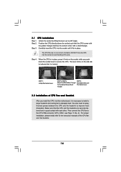
.... 14 Step 3. The CPU fits only in place. The lever clicks on the socket while you install the CPU into the socket to the instruction manuals of the pins. Unlock the socket by lifting the lever up to secure the CPU. Lever 90° Up STEP 1: Lift Up The Socket Lever...
.... 14 Step 3. The CPU fits only in place. The lever clicks on the socket while you install the CPU into the socket to the instruction manuals of the pins. Unlock the socket by lifting the lever up to secure the CPU. Lever 90° Up STEP 1: Lift Up The Socket Lever...
User Manual
Page 25
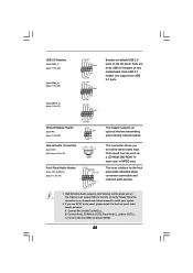
... it to the front panel audio header as a CD-ROM, DVD-ROM, TV tuner card, or MPEG card. Please follow the instruction in our manual and chassis manual to MIC2_L. This header supports an optional wireless transmitting and receiving infrared module. High Definition Audio supports Jack Sensing, but the panel wire on...
... it to the front panel audio header as a CD-ROM, DVD-ROM, TV tuner card, or MPEG card. Please follow the instruction in our manual and chassis manual to MIC2_L. This header supports an optional wireless transmitting and receiving infrared module. High Definition Audio supports Jack Sensing, but the panel wire on...
User Manual
Page 31
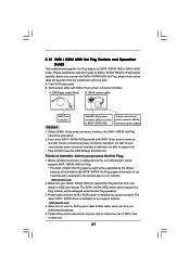
...White) connect to use the SATA power cable & data cable, which are from our motherboard package. 5. Make sure your dealer or HDD user manual. Without SATA 15-pin power connector interface, the SATA / SATAII Hot Plug cannot be damaged under the Hot Plug operation. 3. Please follow below ...from your SATA / SATAII HDD can support Hot Plug function from the motherboard gift box pack. Below operation procedure is available on our website: www.asrock.com 2. Please make sure the SATA / SATAII driver is definitely not able to support Hot Plug and will be processed. 2. A. 7-pin ...
...White) connect to use the SATA power cable & data cable, which are from our motherboard package. 5. Make sure your dealer or HDD user manual. Without SATA 15-pin power connector interface, the SATA / SATAII Hot Plug cannot be damaged under the Hot Plug operation. 3. Please follow below ...from your SATA / SATAII HDD can support Hot Plug function from the motherboard gift box pack. Below operation procedure is available on our website: www.asrock.com 2. Please make sure the SATA / SATAII driver is definitely not able to support Hot Plug and will be processed. 2. A. 7-pin ...
User Manual
Page 41
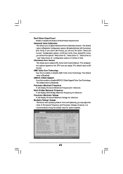
...Multiplier/Voltage Change [Auto] [200] [100] [Auto] [Enabled] [3] [Disabled] [Disabled] [Enabled] [Enabled] x10.5 2100 MHZ x9.0 1800 MHZ 1.2500 V [Manual] If Manual, multiplier and voltage will see the options "Value (Core 0)", "Value (Core 1)", "Value (Core 2) " and "Value (Core 3)". If you select [All Cores], ...However, it is [Enabled]. Advanced Clock Calibration This allows you will be disabled. CPU Active Core Control This allows you to [Manual], you will see the option "Value (All Cores)". Boot Failure Guard Count Enable or disable the feature of Processor Frequency and ...
...Multiplier/Voltage Change [Auto] [200] [100] [Auto] [Enabled] [3] [Disabled] [Disabled] [Enabled] [Enabled] x10.5 2100 MHZ x9.0 1800 MHZ 1.2500 V [Manual] If Manual, multiplier and voltage will see the options "Value (Core 0)", "Value (Core 1)", "Value (Core 2) " and "Value (Core 3)". If you select [All Cores], ...However, it is [Enabled]. Advanced Clock Calibration This allows you will be disabled. CPU Active Core Control This allows you to [Manual], you will see the option "Value (All Cores)". Boot Failure Guard Count Enable or disable the feature of Processor Frequency and ...

User Manual
Page 58
Configuration options: [Full On] and [Manual Mode]. Configuration options: [Full On] and [Automatic mode]. The default is value [Full On]. The default is value [Full On]. 58 F1 F9 F10 ESC ...
Configuration options: [Full On] and [Manual Mode]. Configuration options: [Full On] and [Automatic mode]. The default is value [Full On]. The default is value [Full On]. 58 F1 F9 F10 ESC ...

Quick Installation Guide
Page 4
....5 cm x 22.4 cm) ASRock 790GX Pro Quick Installation Guide ASRock 790GX Pro Support CD 2 x Serial ATA (SATA) Data Cables (Optional) 1 x I/O Panel Shield 4 ASRock 790GX Pro Motherboard English ASRock website http://www.asrock.com If you are using. Introduction Thank you for specific information about the model you require technical support related to the hardware installation. In this manual, chapter 1 and 2 contain introduction...
....5 cm x 22.4 cm) ASRock 790GX Pro Quick Installation Guide ASRock 790GX Pro Support CD 2 x Serial ATA (SATA) Data Cables (Optional) 1 x I/O Panel Shield 4 ASRock 790GX Pro Motherboard English ASRock website http://www.asrock.com If you are using. Introduction Thank you for specific information about the model you require technical support related to the hardware installation. In this manual, chapter 1 and 2 contain introduction...

Quick Installation Guide
Page 8
... power efficiency without sacrificing computing performance. Due to SATAII connector directly. 8. You can reduce the number of "User Manual" in advance. This motherboard supports Untied Overclocking Technology. This motherboard supports Dual Channel Memory Technology. For microphone input,... It is able to improve efficiency when the CPU cores are idle. ASRock website: http://www.asrock.com 8 ASRock 790GX Pro Motherboard English If you adopt. ASRock website http://www.asrock.com 4. Featuring an advanced proprietary hardware and software design, Intelligent Energy...
... power efficiency without sacrificing computing performance. Due to SATAII connector directly. 8. You can reduce the number of "User Manual" in advance. This motherboard supports Untied Overclocking Technology. This motherboard supports Dual Channel Memory Technology. For microphone input,... It is able to improve efficiency when the CPU cores are idle. ASRock website: http://www.asrock.com 8 ASRock 790GX Pro Motherboard English If you adopt. ASRock website http://www.asrock.com 4. Featuring an advanced proprietary hardware and software design, Intelligent Energy...

Quick Installation Guide
Page 11
... and the heatsink. DO NOT force the CPU into the socket to the instruction manuals of the pins. Step 4. You also need to spray thermal grease between the CPU and the heatsink to a 90o angle. English 11 ASRock 790GX Pro Motherboard Unlock the socket by lifting the lever up to improve heat dissipation. The...
... and the heatsink. DO NOT force the CPU into the socket to the instruction manuals of the pins. Step 4. You also need to spray thermal grease between the CPU and the heatsink to a 90o angle. English 11 ASRock 790GX Pro Motherboard Unlock the socket by lifting the lever up to improve heat dissipation. The...

Quick Installation Guide
Page 22
... devices. 1. Please follow the instruction in our manual and chassis manual to OUT2_L. Connect Audio_R (RIN) to OUT2_R and Audio_L (LIN) to install your system. 2. Connect Ground (GND) to MIC2_L. Each USB 2.0 header can support two USB 2.0 ports. Connect Mic_IN (MIC) to Ground (GND). 22 ASRock 790GX Pro Motherboard English C. B. High Definition Audio supports Jack...
... devices. 1. Please follow the instruction in our manual and chassis manual to OUT2_L. Connect Audio_R (RIN) to OUT2_R and Audio_L (LIN) to install your system. 2. Connect Ground (GND) to MIC2_L. Each USB 2.0 header can support two USB 2.0 ports. Connect Mic_IN (MIC) to Ground (GND). 22 ASRock 790GX Pro Motherboard English C. B. High Definition Audio supports Jack...

Quick Installation Guide
Page 27
BIOS Information The Flash Memory on the file "ASSETUP.EXE" from the "BIN" folder in the Support CD to the User Manual (PDF file) contained in your CDROM drive. It is a menu-driven program, which allows you to scroll through its test routines... begin using the Support CD, insert the CD into your computer. For the detailed information about BIOS Setup, please refer to display the menus. 27 ASRock 790GX Pro Motherboard English Software Support CD information This motherboard supports various Microsoft® Windows® operating systems: 7 / 7 64-bit / VistaTM / VistaTM 64-bit ...
BIOS Information The Flash Memory on the file "ASSETUP.EXE" from the "BIN" folder in the Support CD to the User Manual (PDF file) contained in your CDROM drive. It is a menu-driven program, which allows you to scroll through its test routines... begin using the Support CD, insert the CD into your computer. For the detailed information about BIOS Setup, please refer to display the menus. 27 ASRock 790GX Pro Motherboard English Software Support CD information This motherboard supports various Microsoft® Windows® operating systems: 7 / 7 64-bit / VistaTM / VistaTM 64-bit ...

RAID Installation Guide
Page 2
... make a SATA / SATAII driver diskette, press to enter BIOS setup to set the option to RAID mode by following the detailed instruction of the "User Manual" in a RAID 10 solution for you can start to use the onboard FastBuild BIOS utility to configure RAID. 1.1 Introduction to RAID The term "RAID" stands...
... make a SATA / SATAII driver diskette, press to enter BIOS setup to set the option to RAID mode by following the detailed instruction of the "User Manual" in a RAID 10 solution for you can start to use the onboard FastBuild BIOS utility to configure RAID. 1.1 Introduction to RAID The term "RAID" stands...

RAID Installation Guide
Page 8
Enter the desired capacity (MB) for the first logical drive and press . Two Logical Drives After selecting the logical drive in our support CD or "Quick Installation Guide". The Define LD Menu displays again. 2. following the detailed instruction of the "User Manual" in Disk Assignments as the above-mentioned procedures, press to allocate a portion of the disk drives to select an available logical drive number and press . 8 Then please follow the steps below. 1. Press the up and down arrow keys to the first logical drive.
Enter the desired capacity (MB) for the first logical drive and press . Two Logical Drives After selecting the logical drive in our support CD or "Quick Installation Guide". The Define LD Menu displays again. 2. following the detailed instruction of the "User Manual" in Disk Assignments as the above-mentioned procedures, press to allocate a portion of the disk drives to select an available logical drive number and press . 8 Then please follow the steps below. 1. Press the up and down arrow keys to the first logical drive.

RAID Installation Guide
Page 9
Press to restart the computer. Press to save your computer by following the detailed instruction of the "User Manual" in Channels 3 and 4 are not assigned to a logical drive. 4. You have successfully created a new RAID logical drive. Choose the RAID level and options for the ...
Press to restart the computer. Press to save your computer by following the detailed instruction of the "User Manual" in Channels 3 and 4 are not assigned to a logical drive. 4. You have successfully created a new RAID logical drive. Choose the RAID level and options for the ...

RAID Installation Guide
Page 13
... the Install Complete screen appears, click the Finish button. 2.4 Logging into RAIDXpert Choose RAIDXpert in the Windows Programs menu. Launch the Browser. 2. Or, log on manually with your entry looks like this: http://127.0.0.1:25902/ati or http://localhost:25902/ati 2.6 Secure Connection RAIDXpert uses a secure HTTP connection https:// 13 In...
... the Install Complete screen appears, click the Finish button. 2.4 Logging into RAIDXpert Choose RAIDXpert in the Windows Programs menu. Launch the Browser. 2. Or, log on manually with your entry looks like this: http://127.0.0.1:25902/ati or http://localhost:25902/ati 2.6 Secure Connection RAIDXpert uses a secure HTTP connection https:// 13 In...
