User Manual
Page 3
...Layout 11 1.6 HD 8CH I/O 12 2 Installation 13 2.1 Screw Holes 13 2.2 Pre-installation Precautions 13 2.3 CPU Installation 14 2.4 Installation of Heatsink and CPU fan 16 2.5 Installation of Memory Modules (DIMM 17 2.6 Expansion Slots 18 2.7 Surround Display Feature 19 2.8 ... UTILITY 25 3.1 Introduction 25 3.1.1 BIOS Menu Bar 25 3.1.2 Navigation Keys 26 3.2 Main Screen 26 3.3 Advanced Screen 26 3.3.1 CPU Configuration 27 3.3.2 Chipset Configuration 29 3.3.3 ACPI Configuration 31 3.3.4 IDE Configuration 32 3.3.5 PCIPnP Configuration 34 3.3.6 Floppy Configuration 35 3.3.7 Super ...
...Layout 11 1.6 HD 8CH I/O 12 2 Installation 13 2.1 Screw Holes 13 2.2 Pre-installation Precautions 13 2.3 CPU Installation 14 2.4 Installation of Heatsink and CPU fan 16 2.5 Installation of Memory Modules (DIMM 17 2.6 Expansion Slots 18 2.7 Surround Display Feature 19 2.8 ... UTILITY 25 3.1 Introduction 25 3.1.1 BIOS Menu Bar 25 3.1.2 Navigation Keys 26 3.2 Main Screen 26 3.3 Advanced Screen 26 3.3.1 CPU Configuration 27 3.3.2 Chipset Configuration 29 3.3.3 ACPI Configuration 31 3.3.4 IDE Configuration 32 3.3.5 PCIPnP Configuration 34 3.3.6 Floppy Configuration 35 3.3.7 Super ...

User Manual
Page 4
3.4 Hardware Health Event Monitoring Screen 37 3.5 Boot Screen 38 3.5.1 Boot Settings Configuration 38 3.6 Security Screen 39 3.7 Exit Screen 40 4 Software Support 41 4.1 Install Operating System 41 4.2 Support CD Information 41 4.2.1 Running Support CD 41 4.2.2 Drivers Menu 41 4.2.3 Utilities Menu 41 4.2.4 "LGA 775 CPU Installation Live Demo" Program .. 41 4.2.5 Contact Information 41 4
3.4 Hardware Health Event Monitoring Screen 37 3.5 Boot Screen 38 3.5.1 Boot Settings Configuration 38 3.6 Security Screen 39 3.7 Exit Screen 40 4 Software Support 41 4.1 Install Operating System 41 4.2 Support CD Information 41 4.2.1 Running Support CD 41 4.2.2 Drivers Menu 41 4.2.3 Utilities Menu 41 4.2.4 "LGA 775 CPU Installation Live Demo" Program .. 41 4.2.5 Contact Information 41 4
User Manual
Page 5
... Support CD. You may find the latest VGA cards and CPU support lists on ASRock website without notice. ASRock website http://www.asrock.com 1.1 Package Contents ASRock 775i945GZ Motherboard (Micro ATX Form Factor: 9.6-in x 8.6-in, 24.4 cm x 21.8 cm) ASRock 775i945GZ Quick Installation Guide ASRock 775i945GZ Support CD (including LGA 775 CPU Installation Live Demo) One 80-conductor Ultra ATA 66...
... Support CD. You may find the latest VGA cards and CPU support lists on ASRock website without notice. ASRock website http://www.asrock.com 1.1 Package Contents ASRock 775i945GZ Motherboard (Micro ATX Form Factor: 9.6-in x 8.6-in, 24.4 cm x 21.8 cm) ASRock 775i945GZ Quick Installation Guide ASRock 775i945GZ Support CD (including LGA 775 CPU Installation Live Demo) One 80-conductor Ultra ATA 66...
User Manual
Page 6
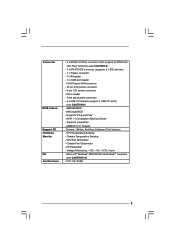
... / Celeron® D, supporting CoreTM 2 Duo Desktop (Conroe), Presler and Cedar Mill processors (in , 24.4 cm x 21.8 cm - ASRock U-COP (see CAUTION 2) - Supports Untied Overclocking Technology (see CAUTION 5) - shared memory 192MB - Supports Hyper-Threading Technology (see CAUTION 4) ...- capacity: 2GB - Max. Speed: 10/100 Ethernet - Supports EM64T CPU - Support DDRII533 - CPU Frequency Stepless Control (see CAUTION 1) - Micro ATX Form Factor: 9.6-in x 8.6-in 775-land LGA package) - Northbridge: ...
... / Celeron® D, supporting CoreTM 2 Duo Desktop (Conroe), Presler and Cedar Mill processors (in , 24.4 cm x 21.8 cm - ASRock U-COP (see CAUTION 2) - Supports Untied Overclocking Technology (see CAUTION 5) - shared memory 192MB - Supports Hyper-Threading Technology (see CAUTION 4) ...- capacity: 2GB - Max. Speed: 10/100 Ethernet - Supports EM64T CPU - Support DDRII533 - CPU Frequency Stepless Control (see CAUTION 1) - Micro ATX Form Factor: 9.6-in x 8.6-in 775-land LGA package) - Northbridge: ...
User Manual
Page 7
... Plug" functions) (see CAUTION 9) - 4Mb AMI BIOS - AMI Legal BIOS - Voltage Monitoring: +12V, +5V, +3.3V, Vcore - ACPI 1.1 Compliance Wake Up Events - AMBIOS 2.3.1 Support - CPU Temperature Sensing - CPU Fan Tachometer - CPU/Chassis FAN connector - 20 pin ATX power connector - 4 pin 12V power connector - Chassis Temperature Sensing - FCC, CE, WHQL 7 Chassis Fan Tachometer - Front panel...
... Plug" functions) (see CAUTION 9) - 4Mb AMI BIOS - AMI Legal BIOS - Voltage Monitoring: +12V, +5V, +3.3V, Vcore - ACPI 1.1 Compliance Wake Up Events - AMBIOS 2.3.1 Support - CPU Temperature Sensing - CPU Fan Tachometer - CPU/Chassis FAN connector - 20 pin ATX power connector - 4 pin 12V power connector - Chassis Temperature Sensing - FCC, CE, WHQL 7 Chassis Fan Tachometer - Front panel...
User Manual
Page 8
...asrock.com 8 Please read "Untied Overclocking Technology" on the motherboard functions properly and unplug the power cord, then plug it is not recommended to our website in the future. This motherboard supports Dual Channel Memory Technology. Although this motherboard offers stepless control, it back again. While CPU... connector directly. 9. Before installing SATAII hard disk to SATAII connector, please read the installation guide of the system or damage the CPU. 5. For the proper installation of PCI Express VGA card, please refer to read the "SATAII Hard Disk Setup Guide" on...
...asrock.com 8 Please read "Untied Overclocking Technology" on the motherboard functions properly and unplug the power cord, then plug it is not recommended to our website in the future. This motherboard supports Dual Channel Memory Technology. Although this motherboard offers stepless control, it back again. While CPU... connector directly. 9. Before installing SATAII hard disk to SATAII connector, please read the installation guide of the system or damage the CPU. 5. For the proper installation of PCI Express VGA card, please refer to read the "SATAII Hard Disk Setup Guide" on...

User Manual
Page 9
1.3 Minimum Hardware Requirement Table for minimum hardware requirement. Please adopt the CPU, memory, and VGA that we suggest. CPU Memory Celeron D 326 512MB x 2 Dual Channel (Premium) 512MB Single Channel (Basic) 256MB x 2 Dual Channel (Basic) * If you use onboard VGA with total system...® VistaTM Premium and Basic Logo For system integrators and users who purchase this motherboard, please refer to Premium Discrete requirement at http://www.asrock.com 9 If you plan to use onboard VGA with total system memory size 512MB and plan to submit Windows® VistaTM Basic logo, ...
1.3 Minimum Hardware Requirement Table for minimum hardware requirement. Please adopt the CPU, memory, and VGA that we suggest. CPU Memory Celeron D 326 512MB x 2 Dual Channel (Premium) 512MB Single Channel (Basic) 256MB x 2 Dual Channel (Basic) * If you use onboard VGA with total system...® VistaTM Premium and Basic Logo For system integrators and users who purchase this motherboard, please refer to Premium Discrete requirement at http://www.asrock.com 9 If you plan to use onboard VGA with total system memory size 512MB and plan to submit Windows® VistaTM Basic logo, ...
User Manual
Page 11
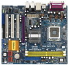
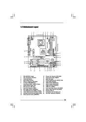
... bit, 240-pin module) DDRII_1 (64/72 bit, 240-pin module) Dual Core CPU VGA1 28 27 26 25 Top: LINE IN Center: FRONT Bottom: MIC IN To p : REAR SPK Center: SIDE SPK Bottom: CTR BASS Presler 775i945GZ USB 2.0 T: USB2 B: USB3 USB 2.0 T: USB0 B: USB1 Top: RJ-45 ... 11 12 13 14 15 1 PS2_USB_PWR1 Jumper 15 Chassis Fan Connector (CHA_FAN1) 2 ATX 12V Connector (ATX12V1) 16 System Panel Header (PANEL1) 3 775-Pin CPU Socket 17 BIOS FWH Chip 4 North Bridge Controller 18 Primary SATAII Connector (SATAII_1; Red) 28 ATX Power Connector (ATXPWR1) 14 Chassis Speaker Header (SPEAKER 1)...
... bit, 240-pin module) DDRII_1 (64/72 bit, 240-pin module) Dual Core CPU VGA1 28 27 26 25 Top: LINE IN Center: FRONT Bottom: MIC IN To p : REAR SPK Center: SIDE SPK Bottom: CTR BASS Presler 775i945GZ USB 2.0 T: USB2 B: USB3 USB 2.0 T: USB0 B: USB1 Top: RJ-45 ... 11 12 13 14 15 1 PS2_USB_PWR1 Jumper 15 Chassis Fan Connector (CHA_FAN1) 2 ATX 12V Connector (ATX12V1) 16 System Panel Header (PANEL1) 3 775-Pin CPU Socket 17 BIOS FWH Chip 4 North Bridge Controller 18 Primary SATAII Connector (SATAII_1; Red) 28 ATX Power Connector (ATXPWR1) 14 Chassis Speaker Header (SPEAKER 1)...

User Manual
Page 14
...pin on the ShoockoetkMatrokedcCleoranerr retention tab. Do not force to fully open position at approximately 100 degrees. Step 1. Step 1-2. Otherwise, the CPU will be seriously damaged. Locate Pin1 and the two orientation key notches. Step 2. Pin1 orientation key notch orientation key notch Pin1 alignment... key alignment key 775-LAND CPU 14 775-Pin Socket black line black line Hold the CPU by depressing down and out on the socket. Rotate the load lever to fully open position ...
...pin on the ShoockoetkMatrokedcCleoranerr retention tab. Do not force to fully open position at approximately 100 degrees. Step 1. Step 1-2. Otherwise, the CPU will be seriously damaged. Locate Pin1 and the two orientation key notches. Step 2. Pin1 orientation key notch orientation key notch Pin1 alignment... key alignment key 775-LAND CPU 14 775-Pin Socket black line black line Hold the CPU by depressing down and out on the socket. Rotate the load lever to fully open position ...

User Manual
Page 15
For proper inserting, please ensure to match the two orientation key notches of the CPU with the two alignment keys of PnP cap to assist in removal. 1. It is within the socket and properly mated to handle and avoid kicking ... load lever with right hand thumb and peel the cap from the socket while pressing on load plate, engage the load lever. Carefully place the CPU into the socket by using a purely vertical motion. Step 4. Rotate the load plate onto the IHS. While pressing down lightly on center of the socket...
For proper inserting, please ensure to match the two orientation key notches of the CPU with the two alignment keys of PnP cap to assist in removal. 1. It is within the socket and properly mated to handle and avoid kicking ... load lever with right hand thumb and peel the cap from the socket while pressing on load plate, engage the load lever. Carefully place the CPU into the socket by using a purely vertical motion. Step 4. Rotate the load plate onto the IHS. While pressing down lightly on center of the socket...

User Manual
Page 16
... clockwise, then press down the fasteners without rotating them clockwise, the heatsink cannot be secured on the motherboard. Step 6. Then connect the CPU fan to the CPU_FAN connector (CPU_FAN1, see page 11, No. 5). For proper installation, please kindly refer to the instruction manuals of .... 16 Ensure fan cables are securely fastened and in good contact with Intel 775-LAND CPU to dissipate heat. Align fasteners with remaining fasteners. Ensure that supports Intel 775-LAND CPU. Connect fan header with fan operation or contact other . Step 1. Secure excess cable ...
... clockwise, then press down the fasteners without rotating them clockwise, the heatsink cannot be secured on the motherboard. Step 6. Then connect the CPU fan to the CPU_FAN connector (CPU_FAN1, see page 11, No. 5). For proper installation, please kindly refer to the instruction manuals of .... 16 Ensure fan cables are securely fastened and in good contact with Intel 775-LAND CPU to dissipate heat. Align fasteners with remaining fasteners. Ensure that supports Intel 775-LAND CPU. Connect fan header with fan operation or contact other . Step 1. Secure excess cable ...

User Manual
Page 22
...) (see p.11 No. 16) Chassis Speaker Header (4-pin SPEAKER 1) (see p.11 No. 5) GND +12V CPU_FAN_SPEED FAN_SPEED_CONTROL Please connect a CPU fan cable to this connector and match the black wire to the ground pin. CPU Fan Connector (4-pin CPU_FAN1) (see p.11 No. 14) PLED+ PLEDPWRBTN# GND 1 DUMMY RESET# GND HDLEDHDLED+ 1 SPEAKER DUMMY DUMMY...
...) (see p.11 No. 16) Chassis Speaker Header (4-pin SPEAKER 1) (see p.11 No. 5) GND +12V CPU_FAN_SPEED FAN_SPEED_CONTROL Please connect a CPU fan cable to this connector and match the black wire to the ground pin. CPU Fan Connector (4-pin CPU_FAN1) (see p.11 No. 14) PLED+ PLEDPWRBTN# GND 1 DUMMY RESET# GND HDLEDHDLED+ 1 SPEAKER DUMMY DUMMY...
User Manual
Page 24
...Installation This motherboard adopts Intel® ICH7 south bridge chipset that FSB can operate under a more stable overclocking environment. 24 You may set "CPU Host Frequency" option of the SATA data cable to the motherboard's SATAII connector. You may install SATA / SATAII hard disks on this ...motherboard. This section will show you the actual CPU host frequency in the following item. STEP 3: Connect one end of BIOS setup to [Auto], which means during overclocking, but in the...
...Installation This motherboard adopts Intel® ICH7 south bridge chipset that FSB can operate under a more stable overclocking environment. 24 You may set "CPU Host Frequency" option of the SATA data cable to the motherboard's SATAII connector. You may install SATA / SATAII hard disks on this ...motherboard. This section will show you the actual CPU host frequency in the following item. STEP 3: Connect one end of BIOS setup to [Auto], which means during overclocking, but in the...
User Manual
Page 26
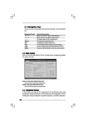
3.1.2 Navigation Keys Please check the following table for the following items: CPU Configuration, Chipset Configuration, ACPI Configuration, IDE Configuration, PCIPnP Configuration, Floppy Configuration, SuperIO Configuration, and USB Configuration. 26 System Time [Hour:Minute... Advanced H/W Monitor Boot Security Exit System Overview System Time System Date [14:00:09] [Fri 05/26/2006] BIOS Version : 775i945GZ BIOS P1.00 Processor Type : Intel (R) CPU 3.40 GHz (64bit supported) Processor Speed : 3400 MHz Microcode Update : F34/17 Cache Size : 1024KB Total Memory : 512MB with...
3.1.2 Navigation Keys Please check the following table for the following items: CPU Configuration, Chipset Configuration, ACPI Configuration, IDE Configuration, PCIPnP Configuration, Floppy Configuration, SuperIO Configuration, and USB Configuration. 26 System Time [Hour:Minute... Advanced H/W Monitor Boot Security Exit System Overview System Time System Date [14:00:09] [Fri 05/26/2006] BIOS Version : 775i945GZ BIOS P1.00 Processor Type : Intel (R) CPU 3.40 GHz (64bit supported) Processor Speed : 3400 MHz Microcode Update : F34/17 Cache Size : 1024KB Total Memory : 512MB with...
User Manual
Page 27
...Intel (R) SpeedStep(tm) tech. [Disabled] [Disabled] [Enabled] [Enabled] [Disabled] [Enabled] [Auto] Select how to malfunction. 3.3.1 CPU Configuration BIOS SETUP UTILITY Advanced CPU Configuration CPU Host Frequency Actual Frequency (MHz) Boot Failure Guard Spread Spectrum [Auto] [200] [Enabled] [Auto] Ratio Status Unlocked (Max :17...Monitor Boot Security Exit Advanced Settings WARNING : Setting wrong values in below sections may cause the system to set the CPU host frequency. +F1 F9 F10 ESC Select Screen Select Item Change Option General Help Load Defaults Save and Exit Exit ...
...Intel (R) SpeedStep(tm) tech. [Disabled] [Disabled] [Enabled] [Enabled] [Disabled] [Enabled] [Auto] Select how to malfunction. 3.3.1 CPU Configuration BIOS SETUP UTILITY Advanced CPU Configuration CPU Host Frequency Actual Frequency (MHz) Boot Failure Guard Spread Spectrum [Auto] [200] [Enabled] [Auto] Ratio Status Unlocked (Max :17...Monitor Boot Security Exit Advanced Settings WARNING : Setting wrong values in below sections may cause the system to set the CPU host frequency. +F1 F9 F10 ESC Select Screen Select Item Change Option General Help Load Defaults Save and Exit Exit ...

User Manual
Page 28
... (NX) Memory Protection Technology is set the "Power Schemes" as Microsoft® Windows® XP. Max CPUID Value Limit For Prescott CPU only, some OSes (ex. When this motherboard. This option will find this item appear to enable this motherboard. Set to execute code.... supports Hyper-Threading technology and an operating system that cannot support CPUs with disable. This option will be hidden if the installed CPU does not support Intel (R) Virtualization Technology. Processor can prevent data pages from being used by Vanderpool Technology. NT4.0) cannot handle the...
... (NX) Memory Protection Technology is set the "Power Schemes" as Microsoft® Windows® XP. Max CPUID Value Limit For Prescott CPU only, some OSes (ex. When this motherboard. This option will find this item appear to enable this motherboard. Set to execute code.... supports Hyper-Threading technology and an operating system that cannot support CPUs with disable. This option will be hidden if the installed CPU does not support Intel (R) Virtualization Technology. Processor can prevent data pages from being used by Vanderpool Technology. NT4.0) cannot handle the...

User Manual
Page 37
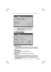
... default value is [50]. Target Fan Speed Use this option to the target CPU temperature that you adjusting them. Tolerance ( C) The default value of tolerance is [Fast]. Target CPU Temperature ( C) The target temperature will operate in full speed. You can freely...speed, and the critical voltage. BIOS SETUP UTILITY Main Advanced H/W Monitor Boot Security Exit Hardware Health Event Monitoring CPU Temperature M / B Temperature : 37 C / 98 F : 31 C / 87 F Target Fan Speed Fast Middle Slow CPU Fan Speed Chassis Fan Speed : 3400 RPM : N/A Vcore + 3.30V + 5.00V + 12.00V :...
... default value is [50]. Target Fan Speed Use this option to the target CPU temperature that you adjusting them. Tolerance ( C) The default value of tolerance is [Fast]. Target CPU Temperature ( C) The target temperature will operate in full speed. You can freely...speed, and the critical voltage. BIOS SETUP UTILITY Main Advanced H/W Monitor Boot Security Exit Hardware Health Event Monitoring CPU Temperature M / B Temperature : 37 C / 98 F : 31 C / 87 F Target Fan Speed Fast Middle Slow CPU Fan Speed Chassis Fan Speed : 3400 RPM : N/A Vcore + 3.30V + 5.00V + 12.00V :...

User Manual
Page 41
... Demo". Click on the file "ASSETUP.EXE" from the BIN folder in order to reduce the risks of CPU and motherboard damages caused by improper handling, ASRock sincerely presents you a clear installation guide through the following path: ..\ MPEGAV \ LGA775INST.DAT 4.2.5 Contact Information If...appear automatically, locate and double click on a specific item then follow the installation wizard to visit ASRock's website at http://www.asrock.com; Since it . 4.2.4 "LGA 775 CPU Installation Live Demo" Program This motherboard is equipped with the motherboard contains necessary drivers and useful ...
... Demo". Click on the file "ASSETUP.EXE" from the BIN folder in order to reduce the risks of CPU and motherboard damages caused by improper handling, ASRock sincerely presents you a clear installation guide through the following path: ..\ MPEGAV \ LGA775INST.DAT 4.2.5 Contact Information If...appear automatically, locate and double click on a specific item then follow the installation wizard to visit ASRock's website at http://www.asrock.com; Since it . 4.2.4 "LGA 775 CPU Installation Live Demo" Program This motherboard is equipped with the motherboard contains necessary drivers and useful ...

Quick Installation Guide
Page 2
...12 Fourth SATAII Connector (SATAII_4; Red) 5 CPU Fan Connector (CPU_FAN1) 19 South Bridge Controller 6 2 x 240-pin DDRII DIMM Slots 20 USB 2.0 Header (USB67, Blue) (Dual Channel: DDRII_1, DDRII_2; Red) 28 ATX Power Connector (ATXPWR1) 14 Chassis Speaker Header (SPEAKER 1) 2 ASRock 775i945GZ Motherboard Orange) 27 AGI Express Slot (PCI ... English 1 PS2_USB_PWR1 Jumper 15 Chassis Fan Connector (CHA_FAN1) 2 ATX 12V Connector (ATX12V1) 16 System Panel Header (PANEL1) 3 775-Pin CPU Socket 17 BIOS FWH Chip 4 North Bridge Controller 18 Primary SATAII Connector (SATAII_1;
...12 Fourth SATAII Connector (SATAII_4; Red) 5 CPU Fan Connector (CPU_FAN1) 19 South Bridge Controller 6 2 x 240-pin DDRII DIMM Slots 20 USB 2.0 Header (USB67, Blue) (Dual Channel: DDRII_1, DDRII_2; Red) 28 ATX Power Connector (ATXPWR1) 14 Chassis Speaker Header (SPEAKER 1) 2 ASRock 775i945GZ Motherboard Orange) 27 AGI Express Slot (PCI ... English 1 PS2_USB_PWR1 Jumper 15 Chassis Fan Connector (CHA_FAN1) 2 ATX 12V Connector (ATX12V1) 16 System Panel Header (PANEL1) 3 775-Pin CPU Socket 17 BIOS FWH Chip 4 North Bridge Controller 18 Primary SATAII Connector (SATAII_1;

Quick Installation Guide
Page 4
... of this manual occur, the updated version will be available on ASRock website as well. ASRock website http://www.asrock.com 1.1 Package Contents ASRock 775i945GZ Motherboard (Micro ATX Form Factor: 9.6-in x 8.6-in, 24.4 cm x 21.8 cm) ASRock 775i945GZ Quick Installation Guide ASRock 775i945GZ Support CD (including LGA 775 CPU Installation Live Demo) One 80-conductor Ultra ATA 66/100 IDE...
... of this manual occur, the updated version will be available on ASRock website as well. ASRock website http://www.asrock.com 1.1 Package Contents ASRock 775i945GZ Motherboard (Micro ATX Form Factor: 9.6-in x 8.6-in, 24.4 cm x 21.8 cm) ASRock 775i945GZ Quick Installation Guide ASRock 775i945GZ Support CD (including LGA 775 CPU Installation Live Demo) One 80-conductor Ultra ATA 66/100 IDE...


