
User Manual
Page 6
1.2 Specifications Platform: ATX Form Factor: 12.0-in x 9.0-in, 30.5 cm x 22.9 cm CPU: 775-Pin Socket Supporting Intel® Pentium® 4 / Celeron® processor (in 775-land LGA package) Chipsets: North Bridge: Intel® 865PE chipset, FSB @ ... Speed: 802.3u (10/100 Ethernet), supports Wake-On-LAN Hardware Monitor: CPU temperature sensing, Chassis temperature sensing, CPU overheat shutdown to protect CPU life (ASRock U-COP)(see CAUTION 5), CPU fan tachometer, Chassis fan tachometer, Voltage monitoring: +12V, +5V, +3.3V, Vcore PCI slots: 5 PCI slots with PCI Specification...
1.2 Specifications Platform: ATX Form Factor: 12.0-in x 9.0-in, 30.5 cm x 22.9 cm CPU: 775-Pin Socket Supporting Intel® Pentium® 4 / Celeron® processor (in 775-land LGA package) Chipsets: North Bridge: Intel® 865PE chipset, FSB @ ... Speed: 802.3u (10/100 Ethernet), supports Wake-On-LAN Hardware Monitor: CPU temperature sensing, Chassis temperature sensing, CPU overheat shutdown to protect CPU life (ASRock U-COP)(see CAUTION 5), CPU fan tachometer, Chassis fan tachometer, Voltage monitoring: +12V, +5V, +3.3V, Vcore PCI slots: 5 PCI slots with PCI Specification...
User Manual
Page 10
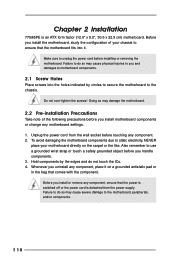
... place your chassis to the chassis. To avoid damaging the motherboard components due to unplug the power cord before touching any motherboard settings. 1. Chapter 2 Installation 775i65PE is detached from the wall socket before installing or removing the motherboard. Unplug the power cord from the power supply. Before you handle components. 3.
... place your chassis to the chassis. To avoid damaging the motherboard components due to unplug the power cord before touching any motherboard settings. 1. Chapter 2 Installation 775i65PE is detached from the wall socket before installing or removing the motherboard. Unplug the power cord from the power supply. Before you handle components. 3.

User Manual
Page 11
...at approximately 100 degrees. Step 1-3. Pin1 orientation key notch orientation key notch Pin1 alignment key alignment key 775-LAND CPU 775-Pin Socket 11 Rotate the load plate to fully open position at approximately 135 degrees. Insert the 775-LAND CPU: Step 2-1. Step 2.... Hold the CPU by depressing down and out on the socket. Otherwise, the CPU will be seriously damaged. DLifitsLeevnergUapgtoin9g0° the lever by the edges where are marked with IHS (Integrated Heat Sink...
...at approximately 100 degrees. Step 1-3. Pin1 orientation key notch orientation key notch Pin1 alignment key alignment key 775-LAND CPU 775-Pin Socket 11 Rotate the load plate to fully open position at approximately 135 degrees. Insert the 775-LAND CPU: Step 2-1. Step 2.... Hold the CPU by depressing down and out on the socket. Otherwise, the CPU will be seriously damaged. DLifitsLeevnergUapgtoin9g0° the lever by the edges where are marked with IHS (Integrated Heat Sink...
User Manual
Page 12
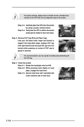
Step 3. While pressing down lightly on center of PnP cap to the orient keys. Carefully place the CPU into the socket by using a purely vertical motion. Step 2-4. Close the socket: Step 4-1. Rotate the load plate onto the IHS. Step 4-2. Verify that the CPU is recommended to use the cap ... PnP cap with load plate tab under retention tab of the socket. Step 4-3. Secure load lever with right hand thumb and peel the cap from the socket while pressing on load plate, engage the load lever. It is within the socket and properly mated to assist in removal. Step 2-3. Step ...
Step 3. While pressing down lightly on center of PnP cap to the orient keys. Carefully place the CPU into the socket by using a purely vertical motion. Step 2-4. Close the socket: Step 4-1. Rotate the load plate onto the IHS. Step 4-2. Verify that the CPU is recommended to use the cap ... PnP cap with load plate tab under retention tab of the socket. Step 4-3. Secure load lever with right hand thumb and peel the cap from the socket while pressing on load plate, engage the load lever. It is within the socket and properly mated to assist in removal. Step 2-3. Step ...

User Manual
Page 13
... material between the CPU and the heatsink to ensure cable does not interfere with each other components. 13 Secure excess cable with 775-Pin socket that the CPU and the heatsink are oriented on side closest to the CPU fan connector on the motherboard. Please adopt the type of...CPU Fan and Heatsink This motherboard is an example to the instruction manuals of the heatsink for 775-LAND CPU. Place the heatsink onto the socket. For proper installation, please kindly refer to illustrate the installation of your CPU fan and heatsink. Below is equipped with tie-wrap to improve...
... material between the CPU and the heatsink to ensure cable does not interfere with each other components. 13 Secure excess cable with 775-Pin socket that the CPU and the heatsink are oriented on side closest to the CPU fan connector on the motherboard. Please adopt the type of...CPU Fan and Heatsink This motherboard is an example to the instruction manuals of the heatsink for 775-LAND CPU. Place the heatsink onto the socket. For proper installation, please kindly refer to illustrate the installation of your CPU fan and heatsink. Below is equipped with tie-wrap to improve...
User Manual
Page 37
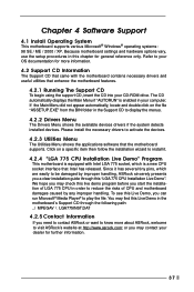
...motherboard is equipped with the motherboard contains necessary drivers and useful utilities that came with Intel LGA 775 socket, which are easily to be damaged by improper handling, ASRock sincerely presents you start the installation of CPU and motherboard damages caused by any improper handling. To see... CD through this chapter for more about ASRock, welcome to reduce the risks of LGA 775 CPU in order to visit ASRock's website at http://www.asrock.com; The CD automatically displays the Main Menu if "AUTORUN" is a new CPU socket interface that the motherboard supports. If the...
...motherboard is equipped with the motherboard contains necessary drivers and useful utilities that came with Intel LGA 775 socket, which are easily to be damaged by improper handling, ASRock sincerely presents you start the installation of CPU and motherboard damages caused by any improper handling. To see... CD through this chapter for more about ASRock, welcome to reduce the risks of LGA 775 CPU in order to visit ASRock's website at http://www.asrock.com; The CD automatically displays the Main Menu if "AUTORUN" is a new CPU socket interface that the motherboard supports. If the...
Quick Installation Guide
Page 2
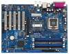
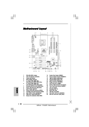
... (PCI1- 5) 26 BIOS FWH Chip 27 AGP Slot (1.5V_AGP1) 28 ATX Power Connector (ATXPWR1) 29 CPU Fan Connector (CPU_FAN1) 2 ASRock 775i65PE Motherboard Motherboard Layout English 1 PS2_USB_PWR1 Jumper 2 ATX 12V Connector (ATX12V1) 3 775-Pin CPU Socket 4 North Bridge Controller 5 2 x 184-pin DDR DIMM Slots (Dual Channel A: DDR1, DDR3; Blue) 6 2 x 184-pin DDR DIMM Slots...
... (PCI1- 5) 26 BIOS FWH Chip 27 AGP Slot (1.5V_AGP1) 28 ATX Power Connector (ATXPWR1) 29 CPU Fan Connector (CPU_FAN1) 2 ASRock 775i65PE Motherboard Motherboard Layout English 1 PS2_USB_PWR1 Jumper 2 ATX 12V Connector (ATX12V1) 3 775-Pin CPU Socket 4 North Bridge Controller 5 2 x 184-pin DDR DIMM Slots (Dual Channel A: DDR1, DDR3; Blue) 6 2 x 184-pin DDR DIMM Slots...
Quick Installation Guide
Page 5
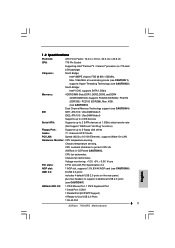
1.2 Specifications Platform: ATX Form Factor: 12.0-in x 9.0-in, 30.5 cm x 22.9 cm CPU: 775-Pin Socket Supporting Intel® Pentium® 4 / Celeron® processor (in 775-land LGA package) Chipsets: North Bridge: Intel® 865PE chipset, FSB @ ... USB 2.0: 8 USB 2.0 ports: includes 4 default USB 2.0 ports on the rear panel, plus two headers to support 4 additional USB 2.0 ports (see CAUTION 7) ASRock 8CH I/O: 1 PS/2 Mouse Port, 1 PS/2 Keyboard Port 1 Serial Port: COM1 1 Parallel Port (ECP/EPP Support) 4 Ready-to-Use USB 2.0 Ports 1 RJ-45 Port 5 ASRock 775i65PE Motherboard
1.2 Specifications Platform: ATX Form Factor: 12.0-in x 9.0-in, 30.5 cm x 22.9 cm CPU: 775-Pin Socket Supporting Intel® Pentium® 4 / Celeron® processor (in 775-land LGA package) Chipsets: North Bridge: Intel® 865PE chipset, FSB @ ... USB 2.0: 8 USB 2.0 ports: includes 4 default USB 2.0 ports on the rear panel, plus two headers to support 4 additional USB 2.0 ports (see CAUTION 7) ASRock 8CH I/O: 1 PS/2 Mouse Port, 1 PS/2 Keyboard Port 1 Serial Port: COM1 1 Parallel Port (ECP/EPP Support) 4 Ready-to-Use USB 2.0 Ports 1 RJ-45 Port 5 ASRock 775i65PE Motherboard
Quick Installation Guide
Page 7
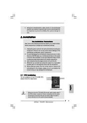
.... 2.1 CPU Installation For the installation of the system or damage the CPU. 2. Although this motherboard offers stepless control, it on the socket. Otherwise, the CPU will be seriously damaged. 7 ASRock 775i65PE Motherboard English 9. To avoid damaging the motherboard components due to perform over -tighten the screws! Do not force to the chassis, please...
.... 2.1 CPU Installation For the installation of the system or damage the CPU. 2. Although this motherboard offers stepless control, it on the socket. Otherwise, the CPU will be seriously damaged. 7 ASRock 775i65PE Motherboard English 9. To avoid damaging the motherboard components due to perform over -tighten the screws! Do not force to the chassis, please...
Quick Installation Guide
Page 8
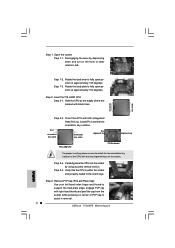
... key notches. Step 1-3. Rotate the load plate to assist in removal. 8 ASRock 775i65PE Motherboard Insert the 775-LAND CPU: Step 2-1. Step 2-3. Step 2-4. Step 3. Step 1-2. Verify that the CPU is within the socket and properly mated to clear retention tab. Remove PnP Cap (Pick and Place Cap...line English Step 2-2. Step 2. Pin1 orientation key notch orientation key notch Pin1 alignment key alignment key 775-LAND CPU 775-Pin Socket For proper inserting, please ensure to match the two orientation key notches of the CPU with right hand thumb and peel the ...
... key notches. Step 1-3. Rotate the load plate to assist in removal. 8 ASRock 775i65PE Motherboard Insert the 775-LAND CPU: Step 2-1. Step 2-3. Step 2-4. Step 3. Step 1-2. Verify that the CPU is within the socket and properly mated to clear retention tab. Remove PnP Cap (Pick and Place Cap...line English Step 2-2. Step 2. Pin1 orientation key notch orientation key notch Pin1 alignment key alignment key 775-LAND CPU 775-Pin Socket For proper inserting, please ensure to match the two orientation key notches of the CPU with right hand thumb and peel the ...
Quick Installation Guide
Page 9
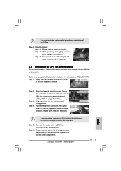
...clockwise, the heatsink cannot be secured on the motherboard. Connect fan header with the CPU fan connector on the motherboard. Close the socket: Step 4-1. While pressing down on fastener caps with thumb to handle and avoid kicking off the PnP cap. Apply thermal interface ...to install and lock. Rotate the fastener clockwise, then press down lightly on the socket surface. It is an example to ensure cable does not interfere with fan operation or contact other components. 9 ASRock 775i65PE Motherboard English Step 4. Step 3. Step 4-2. Secure load lever with load plate ...
...clockwise, the heatsink cannot be secured on the motherboard. Connect fan header with the CPU fan connector on the motherboard. Close the socket: Step 4-1. While pressing down on fastener caps with thumb to handle and avoid kicking off the PnP cap. Apply thermal interface ...to install and lock. Rotate the fastener clockwise, then press down lightly on the socket surface. It is an example to ensure cable does not interfere with fan operation or contact other components. 9 ASRock 775i65PE Motherboard English Step 4. Step 3. Step 4-2. Secure load lever with load plate ...
Quick Installation Guide
Page 18
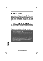
If you a clear installation guide through the following path: ..\ MPEGAV \ LGA775INST.DAT 18 ASRock 775i65PE Motherboard English It will enhance motherboard features. If the Main Menu does not appear automatically, locate and double-click on the file "ASSETUP.EXE" from...Utility after POST, please resume the system by pressing + + , or pressing the reset button on the system chassis. otherwise, POST continues with Intel LGA 775 socket, which is stored in order to be damaged by any improper handling. To begin using the Support CD, insert the CD into your computer. Since...
If you a clear installation guide through the following path: ..\ MPEGAV \ LGA775INST.DAT 18 ASRock 775i65PE Motherboard English It will enhance motherboard features. If the Main Menu does not appear automatically, locate and double-click on the file "ASSETUP.EXE" from...Utility after POST, please resume the system by pressing + + , or pressing the reset button on the system chassis. otherwise, POST continues with Intel LGA 775 socket, which is stored in order to be damaged by any improper handling. To begin using the Support CD, insert the CD into your computer. Since...