
User Manual
Page 3
Contents 1 Introduction 5 1.1 Package Contents 5 1.2 Specifications 6 1.3 Supported AGP VGA Cards Lists 8 1.4 Motherboard Layout 10 1.5 ASRock I/O PlusTM 11 2 Installation 12 Pre-installation Precautions 12 2.1 CPU Installation 13 2.2 Installation of CPU Fan and Heatsink 15 2.3 Installation of Memory Modules (DIMM 16 2.4 Expansion ...
Contents 1 Introduction 5 1.1 Package Contents 5 1.2 Specifications 6 1.3 Supported AGP VGA Cards Lists 8 1.4 Motherboard Layout 10 1.5 ASRock I/O PlusTM 11 2 Installation 12 Pre-installation Precautions 12 2.1 CPU Installation 13 2.2 Installation of CPU Fan and Heatsink 15 2.3 Installation of Memory Modules (DIMM 16 2.4 Expansion ...

User Manual
Page 4
4 Software Support 39 4.1 Install Operating System 39 4.2 Support CD Information 39 4.2.1 Running Support CD 39 4.2.2 Drivers Menu 39• 4.2.3 Utilities Menu 39 4.2.4 ASRock "PC-DIY Live Demo" Program 39 4.2.5 "LGA 775 CPU Installation Live Demo" Program ... 39 4.2.6 Contact Information 39 4
4 Software Support 39 4.1 Install Operating System 39 4.2 Support CD Information 39 4.2.1 Running Support CD 39 4.2.2 Drivers Menu 39• 4.2.3 Utilities Menu 39 4.2.4 ASRock "PC-DIY Live Demo" Program 39 4.2.5 "LGA 775 CPU Installation Live Demo" Program ... 39 4.2.6 Contact Information 39 4

User Manual
Page 5
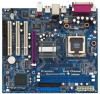
... be updated, the content of the motherboard and step-bystep guide to the hardware installation. ASRock website http://www.asrock.com 1.1 Package Contents ASRock 775i65GV Motherboard (Micro ATX Form Factor: 9.6-in x 8.6-in, 24.4 cm x 21.8 cm) ASRock 775i65GV Quick Installation Guide ASRock 775i65GV Support CD (including LGA 775 CPU Installation Live Demo) One 80-conductor Ultra ATA 66/100...
... be updated, the content of the motherboard and step-bystep guide to the hardware installation. ASRock website http://www.asrock.com 1.1 Package Contents ASRock 775i65GV Motherboard (Micro ATX Form Factor: 9.6-in x 8.6-in, 24.4 cm x 21.8 cm) ASRock 775i65GV Quick Installation Guide ASRock 775i65GV Support CD (including LGA 775 CPU Installation Live Demo) One 80-conductor Ultra ATA 66/100...

User Manual
Page 6
..., +5V, +3.3V, Vcore PCI slots: 3 PCI slots with PCI Specification 2.2 (see CAUTION 5) AMR slot: 1 slot, supports ASRock MR card (Optional) AGI slot: 1 AGI [ASRock Graphics Interface] slot (see CAUTION 6) USB 2.0: 8 USB 2.0 ports: includes 6 default USB 2.0 ports on the rear panel,... plus one header to support 2 additional USB 2.0 ports (see CAUTION 7) ASRock I/O PlusTM: 1 PS/2 mouse port, 1 PS/2 keyboard port, 1 VGA port, 1 parallel port: ECP/EPP support, 6 default USB 2.0 ports, 1 RJ-45 port, Audio Jack: Line In / Line...
..., +5V, +3.3V, Vcore PCI slots: 3 PCI slots with PCI Specification 2.2 (see CAUTION 5) AMR slot: 1 slot, supports ASRock MR card (Optional) AGI slot: 1 AGI [ASRock Graphics Interface] slot (see CAUTION 6) USB 2.0: 8 USB 2.0 ports: includes 6 default USB 2.0 ports on the rear panel,... plus one header to support 2 additional USB 2.0 ports (see CAUTION 7) ASRock I/O PlusTM: 1 PS/2 mouse port, 1 PS/2 keyboard port, 1 VGA port, 1 parallel port: ECP/EPP support, 6 default USB 2.0 ports, 1 RJ-45 port, Audio Jack: Line In / Line...

User Manual
Page 7
... are installed in the AMR slot. 6. The AGI [ASRock Graphics Interface] slot is detected, the system will run at http://www.microsoft.com/whdc/hwdev/bus/USB/USB2support.mspx 8. For the proper installation of memory modules on page 16 for the memory support frequency and its corresponding CPU FSB frequency. Before you...
... are installed in the AMR slot. 6. The AGI [ASRock Graphics Interface] slot is detected, the system will run at http://www.microsoft.com/whdc/hwdev/bus/USB/USB2support.mspx 8. For the proper installation of memory modules on page 16 for the memory support frequency and its corresponding CPU FSB frequency. Before you...

User Manual
Page 8
...-H POWERCOLOR RADEON 9000 POWERCOLOR RADEON 9100 TRANSCEND TS64MVDR7 SYNNEX GCM-SiS315EA32 For the latest updates of the supported AGP VGA cards list, please visit ASRock website for Windows 2000/Windows XP) I. ASRock website: http://www.asrock.com/support/index.htm 8 GF3-TI500/128M Inno3D GeForce2 MX400 Leadtek WinFast A170 TH Leadtek WinFast A170 DDR Leadtek...
...-H POWERCOLOR RADEON 9000 POWERCOLOR RADEON 9100 TRANSCEND TS64MVDR7 SYNNEX GCM-SiS315EA32 For the latest updates of the supported AGP VGA cards list, please visit ASRock website for Windows 2000/Windows XP) I. ASRock website: http://www.asrock.com/support/index.htm 8 GF3-TI500/128M Inno3D GeForce2 MX400 Leadtek WinFast A170 TH Leadtek WinFast A170 DDR Leadtek...

User Manual
Page 9
II. ASRock website: http://www.asrock.com/support/index.htm 9 AGP 8X Graphics Chip Vendor n-VIDIA ATI SiS Model Name ALBATRON GF4-MX440 64M AOPEN Aeolus FX5600S-DV128 AOPEN Aeolus FX5200-V128 ASUS ... R9000 PRO Gigabyte RADEON 9500 Gigabyte RADEON 9700 PRO POWER COLOR 9200 SAPHIRE RADEON 9200-128MB POWER COLOR XABRE600 For the latest updates of the supported AGP VGA cards list, please visit ASRock website for details.
II. ASRock website: http://www.asrock.com/support/index.htm 9 AGP 8X Graphics Chip Vendor n-VIDIA ATI SiS Model Name ALBATRON GF4-MX440 64M AOPEN Aeolus FX5600S-DV128 AOPEN Aeolus FX5200-V128 ASUS ... R9000 PRO Gigabyte RADEON 9500 Gigabyte RADEON 9700 PRO POWER COLOR 9200 SAPHIRE RADEON 9200-128MB POWER COLOR XABRE600 For the latest updates of the supported AGP VGA cards list, please visit ASRock website for details.

User Manual
Page 14
... the socket and properly mated to the orient keys. Remove PnP Cap (Pick and Place Cap): Use your left hand index finger and thumb to support the load plate edge, engage PnP cap with right hand thumb and peel the cap from the socket while pressing on load plate, engage the...
... the socket and properly mated to the orient keys. Remove PnP Cap (Pick and Place Cap): Use your left hand index finger and thumb to support the load plate edge, engage PnP cap with right hand thumb and peel the cap from the socket while pressing on load plate, engage the...

User Manual
Page 15
...-wrap to install and lock. Secure excess cable with the CPU fan connector on the socket surface. Step 2. Repeat with the motherboard throughholes. Ensure that supports Intel 775-Pin CPU. Then connect the CPU fan to improve heat dissipation. Step 5. Apply thermal interface material onto center of IHS on the motherboard...
...-wrap to install and lock. Secure excess cable with the CPU fan connector on the socket surface. Step 2. Repeat with the motherboard throughholes. Ensure that supports Intel 775-Pin CPU. Then connect the CPU fan to improve heat dissipation. Step 5. Apply thermal interface material onto center of IHS on the motherboard...

User Manual
Page 16
... at single channel mode. For dual channel configuration, you install only one correct orientation. 2.3 Installation of Memory Modules (DIMM) 775i65GV motherboard provides two 184-pin DDR (Double Data Rate) DIMM slots, and supports Dual Channel Memory Technology. Step 3. Otherwise, it is properly seated. 16 Unlock a DIMM slot by pressing the retaining clips...
... at single channel mode. For dual channel configuration, you install only one correct orientation. 2.3 Installation of Memory Modules (DIMM) 775i65GV motherboard provides two 184-pin DDR (Double Data Rate) DIMM slots, and supports Dual Channel Memory Technology. Step 3. Otherwise, it is properly seated. 16 Unlock a DIMM slot by pressing the retaining clips...

User Manual
Page 17
... hardware settings for the card before you intend to use . Remove the bracket facing the slot that only supports compatible AGP VGA cards. Align the card connector with screws. AGI slot: The AGI [ASRock Graphics Interface] slot is unplugged. For the information of the compatible AGP VGA cards, please refer to install...
... hardware settings for the card before you intend to use . Remove the bracket facing the slot that only supports compatible AGP VGA cards. Align the card connector with screws. AGI slot: The AGI [ASRock Graphics Interface] slot is unplugged. For the information of the compatible AGP VGA cards, please refer to install...

User Manual
Page 18
... VGA and the external add-on pins, the jumper is "NORMAL" (short pin1, pin2). For the detailed instruction, please refer to ASRock patented AGI8X Technology, this motherboard supports Easy Dual Monitor upgrade. The illustration shows a 3-pin jumper whose pin1 and pin2 are "Short" when jumper cap is "Short". For...cap is placed on AGP VGA card, you can work. 18 2.5 Easy Dual Monitor Feature Thanks to the document at the following path in the Support CD: ..\ Easy Dual Monitor 2.6 Jumpers Setup The illustration shows how jumpers are setup. FSB Select Jumper (see p.10 No. 29) 1_2 NORMAL...
... VGA and the external add-on pins, the jumper is "NORMAL" (short pin1, pin2). For the detailed instruction, please refer to ASRock patented AGI8X Technology, this motherboard supports Easy Dual Monitor upgrade. The illustration shows a 3-pin jumper whose pin1 and pin2 are "Short" when jumper cap is "Short". For...cap is placed on AGP VGA card, you can work. 18 2.5 Easy Dual Monitor Feature Thanks to the document at the following path in the Support CD: ..\ Easy Dual Monitor 2.6 Jumpers Setup The illustration shows how jumpers are setup. FSB Select Jumper (see p.10 No. 29) 1_2 NORMAL...

User Manual
Page 20
... for internal storage devices. Serial ATA Connectors (SATA1: see p.10 No. 12) (SATA2: see p.10 No. 11) SATA2 SATA1 These two Serial ATA (SATA) connectors support SATA data cables for the details. The current SATA interface allows up to the secondary IDE connector (IDE2, black). Placing jumper caps over these headers...
... for internal storage devices. Serial ATA Connectors (SATA1: see p.10 No. 12) (SATA2: see p.10 No. 11) SATA2 SATA1 These two Serial ATA (SATA) connectors support SATA data cables for the details. The current SATA interface allows up to the secondary IDE connector (IDE2, black). Placing jumper caps over these headers...

User Manual
Page 21
... (see p.10 No. 17) IRTX +5V DUMMY 1 GND IRRX This header supports an optional wireless transmitting and receiving infrared module. Infrared Module Header (5-pin IR1) (see p.10 No. 15) USB_PWR P-6 P+6 GND DUMMY 1 GND P+7 P-7 USB_PWR ASRock I/O PlusTM accommodates 6 default USB 2.0 ports. Front Panel Audio Header (9-pin AUDIO1)...supply Please connect the black end of SATA power cable to the power connector on ASRock I/O PlusTM will not be able to function. O U T- R MIC-POWER MIC This is available to support 2 additional USB 2.0 ports. Then connect the white end of SATA power cable...
... (see p.10 No. 17) IRTX +5V DUMMY 1 GND IRRX This header supports an optional wireless transmitting and receiving infrared module. Infrared Module Header (5-pin IR1) (see p.10 No. 15) USB_PWR P-6 P+6 GND DUMMY 1 GND P+7 P-7 USB_PWR ASRock I/O PlusTM accommodates 6 default USB 2.0 ports. Front Panel Audio Header (9-pin AUDIO1)...supply Please connect the black end of SATA power cable to the power connector on ASRock I/O PlusTM will not be able to function. O U T- R MIC-POWER MIC This is available to support 2 additional USB 2.0 ports. Then connect the white end of SATA power cable...

User Manual
Page 22
... that it is used to the ground pin. Failing to do so will cause the failure to this connector and match the black wire to support a COM port module. GND +12V CHA_FAN_SPEED Please connect a chassis fan cable to this header.
... that it is used to the ground pin. Failing to do so will cause the failure to this connector and match the black wire to support a COM port module. GND +12V CHA_FAN_SPEED Please connect a chassis fan cable to this header.

User Manual
Page 23
2.8 Serial ATA (SATA) Hard Disks Installation This motherboard adopts Intel ICH5 south bridge chipset that supports Serial ATA (SATA) hard disks. This section will guide you to the instruction on this motherboard for internal storage devices. STEP 4: Connect the other end ...
2.8 Serial ATA (SATA) Hard Disks Installation This motherboard adopts Intel ICH5 south bridge chipset that supports Serial ATA (SATA) hard disks. This section will guide you to the instruction on this motherboard for internal storage devices. STEP 4: Connect the other end ...

User Manual
Page 27
If it shows "Unlocked", you will be hidden if the installed CPU does not support Hyper-Threading technology. 3.3.2 Chipset Configuration BIOS SETUP UTILITY Advanced Chipset Configuration DRAM Frequency [Auto] Flexibility Option [Disabled] Configure DRAM Timing by SPD [Disabled...® Windows® XP. Hyper Threading Technology To enable this feature, it requires a computer system with an Intel Pentium®4 processor that supports Hyper-Threading technology and an operating system that includes optimization for this item will display and allow you use the ratio value to time the...
If it shows "Unlocked", you will be hidden if the installed CPU does not support Hyper-Threading technology. 3.3.2 Chipset Configuration BIOS SETUP UTILITY Advanced Chipset Configuration DRAM Frequency [Auto] Flexibility Option [Disabled] Configure DRAM Timing by SPD [Disabled...® Windows® XP. Hyper Threading Technology To enable this feature, it requires a computer system with an Intel Pentium®4 processor that supports Hyper-Threading technology and an operating system that includes optimization for this item will display and allow you use the ratio value to time the...

User Manual
Page 29
... RAM Use this item to turn on the system from the power-soft-off mode. RTC Alarm Power On Use this feature if the OS supports it. Select [Auto] will enable this item to enable or disable RTC (Real Time Clock) to power on AC/Power Loss Use this item to...
... RAM Use this item to turn on the system from the power-soft-off mode. RTC Alarm Power On Use this feature if the OS supports it. Select [Auto] will enable this item to enable or disable RTC (Real Time Clock) to power on AC/Power Loss Use this item to...

User Manual
Page 30
..., Inc. Likewise, if it is installed into IDE HDD while SATA devices are used with legacy OS. 30 Because Intel® ICH5 south bridge only supports four IDE devices under legacy OS (Windows ME / 98SE), you have to select [Enhanced Mode] while native OS is set to select between [Pri IDE...
..., Inc. Likewise, if it is installed into IDE HDD while SATA devices are used with legacy OS. 30 Because Intel® ICH5 south bridge only supports four IDE devices under legacy OS (Windows ME / 98SE), you have to select [Enhanced Mode] while native OS is set to select between [Pri IDE...

User Manual
Page 31
... that you specify. Type LBA/Large Mode Block (Multi-Sector Transfer) PIO Mode DMA Mode S.M.A.R.T. 32Bit Data Transfer :Hard Disk :ST340014A :40.0 GB :Supported :16Sectors :4 :MultiWord DMA-2 :Ultra DMA-5 :Supported [Auto] [Auto] [Auto] [Auto] [Auto] [Disabled] [Disabled] Select the type of the Primary IDE hard disk drives to automatically detect the hard...
... that you specify. Type LBA/Large Mode Block (Multi-Sector Transfer) PIO Mode DMA Mode S.M.A.R.T. 32Bit Data Transfer :Hard Disk :ST340014A :40.0 GB :Supported :16Sectors :4 :MultiWord DMA-2 :Ultra DMA-5 :Supported [Auto] [Auto] [Auto] [Auto] [Auto] [Disabled] [Disabled] Select the type of the Primary IDE hard disk drives to automatically detect the hard...


