User Manual
Page 2
With respect to the contents of this motherboard contains Perchlorate, a toxic substance controlled in this manual. CALIFORNIA, USA ONLY The Lithium battery adopted on this manual, ASRock does not provide warranty of any means, except duplication of documentation by the purchaser for ...only for identification or explanation and to the owners' benefit, without notice, and should not be constructed as a commitment by ASRock. Disclaimer: Specifications and information contained in this manual may appear in Perchlorate Best Management Practices (BMP) regulations passed by any...
With respect to the contents of this motherboard contains Perchlorate, a toxic substance controlled in this manual. CALIFORNIA, USA ONLY The Lithium battery adopted on this manual, ASRock does not provide warranty of any means, except duplication of documentation by the purchaser for ...only for identification or explanation and to the owners' benefit, without notice, and should not be constructed as a commitment by ASRock. Disclaimer: Specifications and information contained in this manual may appear in Perchlorate Best Management Practices (BMP) regulations passed by any...
User Manual
Page 3
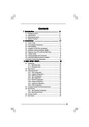
Contents 1 Introduction 5 1.1 Package Contents 5 1.2 Specifications 6 1.3 Motherboard Layout 9 1.4 ASRock I/O PlusTM 10 2 Installation 11 2.1 Screw Holes 11 2.2 Pre-installation Precautions 11 2.3 CPU Installation 12 2.4 Installation of CPU Fan and Heatsink 14 2.5 Installation of Memory Modules (...
Contents 1 Introduction 5 1.1 Package Contents 5 1.2 Specifications 6 1.3 Motherboard Layout 9 1.4 ASRock I/O PlusTM 10 2 Installation 11 2.1 Screw Holes 11 2.2 Pre-installation Precautions 11 2.3 CPU Installation 12 2.4 Installation of CPU Fan and Heatsink 14 2.5 Installation of Memory Modules (...
User Manual
Page 5
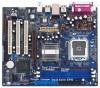
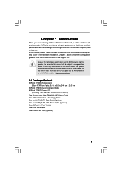
...case any modifications of the Support CD. ASRock website http://www.asrock.com 1.1 Package Contents ASRock 775i65G Motherboard (Micro ATX Form Factor: 9.6-in x 8.0-in, 24.4 cm x 20.3 cm) ASRock 775i65G Quick Installation Guide ASRock 775i65G Support CD (including LGA 775 CPU Installation... Live Demo) One 80-conductor Ultra ATA 66/100 IDE Ribbon Cable One Ribbon Cable for purchasing ASRock 775i65G motherboard, a reliable motherboard produced under ASRock's consistently stringent quality control. Chapter 1 Introduction Thank you for a 3.5-in Floppy Drive One Serial ATA...
...case any modifications of the Support CD. ASRock website http://www.asrock.com 1.1 Package Contents ASRock 775i65G Motherboard (Micro ATX Form Factor: 9.6-in x 8.0-in, 24.4 cm x 20.3 cm) ASRock 775i65G Quick Installation Guide ASRock 775i65G Support CD (including LGA 775 CPU Installation... Live Demo) One 80-conductor Ultra ATA 66/100 IDE Ribbon Cable One Ribbon Cable for purchasing ASRock 775i65G motherboard, a reliable motherboard produced under ASRock's consistently stringent quality control. Chapter 1 Introduction Thank you for a 3.5-in Floppy Drive One Serial ATA...
User Manual
Page 8
...memory modules on page 21 for proper installation. 5. This motherboard supports Untied Overclocking Technology. This motherboard supports Dual Channel Memory Technology. Although this motherboard, it back again. Do NOT use a 3.3V AGP card on the motherboard functions properly and unplug the power cord, then plug it... thermal grease between the CPU and the heatsink when you use an FSB800-CPU on this motherboard! FSB1066-CPU is supported only when you use a FSB1066-CPU on this motherboard offers stepless control, it is detected, the system will run at DDR320 if you adopt ...
...memory modules on page 21 for proper installation. 5. This motherboard supports Untied Overclocking Technology. This motherboard supports Dual Channel Memory Technology. Although this motherboard, it back again. Do NOT use a 3.3V AGP card on the motherboard functions properly and unplug the power cord, then plug it... thermal grease between the CPU and the heatsink when you use an FSB800-CPU on this motherboard! FSB1066-CPU is supported only when you use a FSB1066-CPU on this motherboard offers stepless control, it is detected, the system will run at DDR320 if you adopt ...
User Manual
Page 9
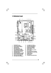
1.3 Motherboard Layout 12 3 4 20.3cm (8.0 in) PS2 Mouse 1 PS2_USB_PWR1 PS2 Keyboard ATX12V1 CPU_FAN1 56 7 DDR400 VGA1 PARALLEL PORT DDR2 (64/72 bit, 184-pin module) Dual ... Top: Line In Center: Line Out Bottom: Mic In Top: RJ-45 USB 2.0 T: USB0 B: USB1 USB 2.0 T: USB2 B: USB3 USB 2.0 1 T: USB4 B: USB5 IDE2 Intel 865G Chipset 775i65G USB4_5 Super I/O ATXPWR1 4Mb BIOS PCI LAN CD1 AUX1 AUDIO CODEC AUDIO1 1 JR1 JL1 AGP8X 1.5V_AGP1 IDE1 RoHS CHA_FAN1 SATA PCI 1 PCI 2 USB2.0 PCI 3 5.1CH...
1.3 Motherboard Layout 12 3 4 20.3cm (8.0 in) PS2 Mouse 1 PS2_USB_PWR1 PS2 Keyboard ATX12V1 CPU_FAN1 56 7 DDR400 VGA1 PARALLEL PORT DDR2 (64/72 bit, 184-pin module) Dual ... Top: Line In Center: Line Out Bottom: Mic In Top: RJ-45 USB 2.0 T: USB0 B: USB1 USB 2.0 T: USB2 B: USB3 USB 2.0 1 T: USB4 B: USB5 IDE2 Intel 865G Chipset 775i65G USB4_5 Super I/O ATXPWR1 4Mb BIOS PCI LAN CD1 AUX1 AUDIO CODEC AUDIO1 1 JR1 JL1 AGP8X 1.5V_AGP1 IDE1 RoHS CHA_FAN1 SATA PCI 1 PCI 2 USB2.0 PCI 3 5.1CH...
User Manual
Page 11
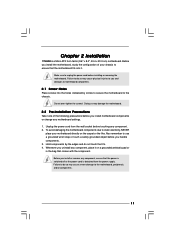
... any component, place it . Before you uninstall any component. 2. To avoid damaging the motherboard components due to the chassis. Whenever you install or remove any motherboard settings. 1. Make sure to use a grounded wrist strap or touch a safety grounded object...you handle components. 3. Before you install the motherboard, study the configuration of the following precautions before you install motherboard components or change any component, ensure that comes with the component. Chapter 2 Installation 775i65G is detached from the wall socket before installing ...
... any component, place it . Before you uninstall any component. 2. To avoid damaging the motherboard components due to the chassis. Whenever you install or remove any motherboard settings. 1. Make sure to use a grounded wrist strap or touch a safety grounded object...you handle components. 3. Before you install the motherboard, study the configuration of the following precautions before you install motherboard components or change any component, ensure that comes with the component. Chapter 2 Installation 775i65G is detached from the wall socket before installing ...
User Manual
Page 13
... hand index finger and thumb to handle and avoid kicking off the PnP cap. 2. Step 2-3. Step 4-2. Step 4-3. This cap must be placed if returning the motherboard for after service. Carefully place the CPU into the socket by using a purely vertical motion. Verify that the CPU is recommended to use the cap...
... hand index finger and thumb to handle and avoid kicking off the PnP cap. 2. Step 2-3. Step 4-2. Step 4-3. This cap must be placed if returning the motherboard for after service. Carefully place the CPU into the socket by using a purely vertical motion. Verify that the CPU is recommended to use the cap...
User Manual
Page 14
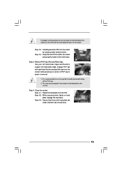
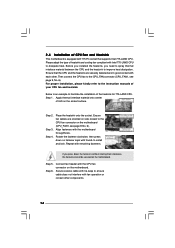
... the socket. Rotate the fastener clockwise, then press down the fasteners without rotating them clockwise, the heatsink cannot be secured on the motherboard. Step 5. Please adopt the type of your CPU fan and heatsink. For proper installation, please kindly refer to the instruction manuals... other . Step 2. Ensure that supports Intel 775-LAND CPU. Step 1. Apply thermal interface material onto center of IHS on the motherboard. If you need to spray thermal interface material between the CPU and the heatsink to improve heat dissipation. Secure excess cable with tie...
... the socket. Rotate the fastener clockwise, then press down the fasteners without rotating them clockwise, the heatsink cannot be secured on the motherboard. Step 5. Please adopt the type of your CPU fan and heatsink. For proper installation, please kindly refer to the instruction manuals... other . Step 2. Ensure that supports Intel 775-LAND CPU. Step 1. Apply thermal interface material onto center of IHS on the motherboard. If you need to spray thermal interface material between the CPU and the heatsink to improve heat dissipation. Secure excess cable with tie...
User Manual
Page 15
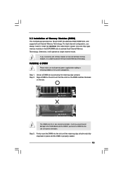
... configuration, you always need to install two identical (the same brand, speed, size and chip-type) memory modules in the DDR DIMM slots to the motherboard and the DIMM if you install only one correct orientation. If you force the DIMM into the slot until the retaining clips at incorrect orientation... components. Align a DIMM on the slot such that the notch on the DIMM matches the break on the slot. 2.5 Installation of Memory Modules (DIMM) This motherboard provides two 184-pin DDR (Double Data Rate) DIMM slots, and supports Dual Channel Memory Technology.
... configuration, you always need to install two identical (the same brand, speed, size and chip-type) memory modules in the DDR DIMM slots to the motherboard and the DIMM if you install only one correct orientation. If you force the DIMM into the slot until the retaining clips at incorrect orientation... components. Align a DIMM on the slot such that the notch on the DIMM matches the break on the slot. 2.5 Installation of Memory Modules (DIMM) This motherboard provides two 184-pin DDR (Double Data Rate) DIMM slots, and supports Dual Channel Memory Technology.
User Manual
Page 16
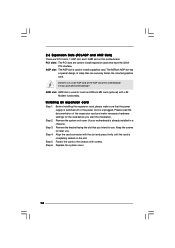
...the card before you intend to use. Step 6. PCI slots: The PCI slots are 3 PCI slots, 1 AGP slot, and 1 AMR slot on this motherboard! Do NOT use . Step 3. Step 5. It may cause permanent damage! Before installing the expansion card, please make necessary hardware settings for later use a... the slot and press firmly until the card is unplugged. Fasten the card to insert an ASRock MR card (optional) with screws. The ASRock AGP slot has a special design of this motherboard. Please read the documentation of the expansion card and make sure that the power supply is...
...the card before you intend to use. Step 6. PCI slots: The PCI slots are 3 PCI slots, 1 AGP slot, and 1 AMR slot on this motherboard! Do NOT use . Step 3. Step 5. It may cause permanent damage! Before installing the expansion card, please make necessary hardware settings for later use a... the slot and press firmly until the card is unplugged. Fasten the card to insert an ASRock MR card (optional) with screws. The ASRock AGP slot has a special design of this motherboard. Please read the documentation of the expansion card and make sure that the power supply is...

User Manual
Page 18
...) Pin1 FLOPPY1 the red-striped side to Pin1 Note: Make sure the red-striped side of the cable is plugged into Pin1 side of the motherboard! Primary IDE connector (Blue) Secondary IDE connector (Black) (39-pin IDE1, see p.9 No. 9) (39-pin IDE2, see p.9 No. 11) SATA2 SATA1 These two Serial... data cable can be connected to the IDE devices 80-conductor ATA 66/100 cable Note: If you use only one IDE device on the motherboard. 18 2.8 Onboard Headers and Connectors Onboard headers and connectors are NOT jumpers. The current SATA interface allows up to the secondary IDE connector (IDE2,...
...) Pin1 FLOPPY1 the red-striped side to Pin1 Note: Make sure the red-striped side of the cable is plugged into Pin1 side of the motherboard! Primary IDE connector (Blue) Secondary IDE connector (Black) (39-pin IDE1, see p.9 No. 9) (39-pin IDE2, see p.9 No. 11) SATA2 SATA1 These two Serial... data cable can be connected to the IDE devices 80-conductor ATA 66/100 cable Note: If you use only one IDE device on the motherboard. 18 2.8 Onboard Headers and Connectors Onboard headers and connectors are NOT jumpers. The current SATA interface allows up to the secondary IDE connector (IDE2,...
User Manual
Page 20
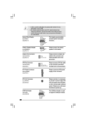
... Connector (20-pin ATXPWR1) (see p.9 No. 6) GND +12V CPU_FAN_SPEED FAN_SPEED_CONTROL Please connect a CPU fan cable to this connector and match the black wire to this motherboard. 1. +5VA is used to this connector. Incorrect connection of the audio front panel and the front panel audio header may cause permanent damage to the...
... Connector (20-pin ATXPWR1) (see p.9 No. 6) GND +12V CPU_FAN_SPEED FAN_SPEED_CONTROL Please connect a CPU fan cable to this connector and match the black wire to this motherboard. 1. +5VA is used to this connector. Incorrect connection of the audio front panel and the front panel audio header may cause permanent damage to the...
User Manual
Page 21
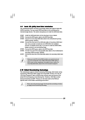
...hard disk. For the configuration details, please refer to install the SATA hard disks. 2.9 Serial ATA (SATA) Hard Disks Installation This motherboard adopts Intel ICH5 south bridge chipset that FSB can operate under a more stable overclocking environment. STEP 6: Connect one SATA HDD, the ...installation process is in the following steps. Please refer to the warning on page 29. 2.10 Untied Overclocking Technology This motherboard supports Untied Overclocking Technology, which will guide you need to check and ensure the configuration of the OnBoard IDE Operate Mode option ...
...hard disk. For the configuration details, please refer to install the SATA hard disks. 2.9 Serial ATA (SATA) Hard Disks Installation This motherboard adopts Intel ICH5 south bridge chipset that FSB can operate under a more stable overclocking environment. STEP 6: Connect one SATA HDD, the ...installation process is in the following steps. Please refer to the warning on page 29. 2.10 Untied Overclocking Technology This motherboard supports Untied Overclocking Technology, which will guide you need to check and ensure the configuration of the OnBoard IDE Operate Mode option ...
User Manual
Page 22
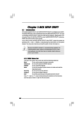
... on . You may run the BIOS SETUP UTILITY when you see on your system. You may also restart by pressing the reset button on the motherboard stores the BIOS SETUP UTILITY. Chapter 3 BIOS SETUP UTILITY 3.1 Introduction This section explains how to use the BIOS SETUP UTILITY to configure your screen. 3.1.1 BIOS...
... on . You may run the BIOS SETUP UTILITY when you see on your system. You may also restart by pressing the reset button on the motherboard stores the BIOS SETUP UTILITY. Chapter 3 BIOS SETUP UTILITY 3.1 Introduction This section explains how to use the BIOS SETUP UTILITY to configure your screen. 3.1.1 BIOS...
User Manual
Page 24
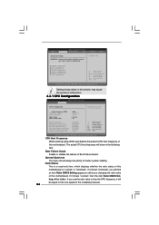
... Status This is "Locked" or "Unlocked". If you changing the ratio value of this motherboard is a read-only item, which displays whether the ratio status of this motherboard. BIOS SETUP UTILITY Main Advanced H/W Monitor Boot Security Exit Advanced Settings WARNING : Setting wrong values in this section may cause system to malfunction. If...
... Status This is "Locked" or "Unlocked". If you changing the ratio value of this motherboard is a read-only item, which displays whether the ratio status of this motherboard. BIOS SETUP UTILITY Main Advanced H/W Monitor Boot Security Exit Advanced Settings WARNING : Setting wrong values in this section may cause system to malfunction. If...
User Manual
Page 25
...Linux kernel version 2.4.18 or higher. Intel (R) SpeedStep(tm) tech. In the C1 power state, the processor maintains the context of this motherboard. The C1 state is Intel's new power saving technology. Set to enable power savings. Hyper Threading Technology To enable this feature, it ...not support Intel (R) Virtualization Technology. This option will find this item appear to allow you need to set to enable this motherboard. is supported through the native processor instructions HLT and MWAIT and requires no hardware support from overheated. This should be hidden ...
...Linux kernel version 2.4.18 or higher. Intel (R) SpeedStep(tm) tech. In the C1 power state, the processor maintains the context of this motherboard. The C1 state is Intel's new power saving technology. Set to enable power savings. Hyper Threading Technology To enable this feature, it ...not support Intel (R) Virtualization Technology. This option will find this item appear to allow you need to set to enable this motherboard. is supported through the native processor instructions HLT and MWAIT and requires no hardware support from overheated. This should be hidden ...
User Manual
Page 26
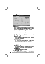
DRAM Frequency If [Auto] is selected, the motherboard will allow better tolerance for RAS minimum. DRAM RAS# to adjust the means of memory accessing. Configura- Graphic Adapter Priority This allows you to select [...
DRAM Frequency If [Auto] is selected, the motherboard will allow better tolerance for RAS minimum. DRAM RAS# to adjust the means of memory accessing. Configura- Graphic Adapter Priority This allows you to select [...

User Manual
Page 34
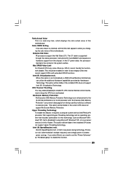
... (C) Copyright 1985-2003, American Megatrends, Inc. The default value is [2], which means the error of CPU fan. Tolerance ( C) The default value of the CPU temperature, motherboard temperature, CPU fan speed, chassis fan speed, and the critical voltage. 3.4 Hardware Health Event Monitoring Screen In this section, it allows you to set the...
... (C) Copyright 1985-2003, American Megatrends, Inc. The default value is [2], which means the error of CPU fan. Tolerance ( C) The default value of the CPU temperature, motherboard temperature, CPU fan speed, chassis fan speed, and the critical voltage. 3.4 Hardware Health Event Monitoring Screen In this section, it allows you to set the...
User Manual
Page 38
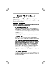
...4.2.3 Utilities Menu The Utilities Menu shows the applications software that enhance the motherboard features. 4.2.1 Running The Support CD To begin using the support CD, insert the CD into your dealer for more about ASRock, welcome to play the file. Since it . 4.2.4 "LGA 775 CPU... before you can run Microsoft® Media Player® to visit ASRock's website at http://www.asrock.com; To see this Live Demo, you start the installation of CPU and motherboard damages caused by improper handling, ASRock sincerely presents you a clear installation guide through the following path: ..\...
...4.2.3 Utilities Menu The Utilities Menu shows the applications software that enhance the motherboard features. 4.2.1 Running The Support CD To begin using the support CD, insert the CD into your dealer for more about ASRock, welcome to play the file. Since it . 4.2.4 "LGA 775 CPU... before you can run Microsoft® Media Player® to visit ASRock's website at http://www.asrock.com; To see this Live Demo, you start the installation of CPU and motherboard damages caused by improper handling, ASRock sincerely presents you a clear installation guide through the following path: ..\...
Quick Installation Guide
Page 1
All rights reserved. 1 ASRock 775i65G Motherboard English ASRock assumes no event shall ASRock, its directors, officers, employees, or agents be liable for any indirect, special, incidental, or consequential damages (including damages for backup purpose, without written consent of ASRock Inc. Disclaimer: Specifications and information contained in this guide...The Lithium battery adopted on this guide may or may not be constructed as a commitment by ASRock. Products and corporate names appearing in this motherboard contains Perchlorate, a toxic substance controlled in advance.
All rights reserved. 1 ASRock 775i65G Motherboard English ASRock assumes no event shall ASRock, its directors, officers, employees, or agents be liable for any indirect, special, incidental, or consequential damages (including damages for backup purpose, without written consent of ASRock Inc. Disclaimer: Specifications and information contained in this guide...The Lithium battery adopted on this guide may or may not be constructed as a commitment by ASRock. Products and corporate names appearing in this motherboard contains Perchlorate, a toxic substance controlled in advance.

