User Manual
Page 3
Contents 1 Introduction 5 1.1 Package Contents 5 1.2 Specifications 6 1.3 Motherboard Layout 9 1.4 ASRock I/O PlusTM 10 2 Installation 11 2.1 Screw Holes 11 2.2 Pre-installation Precautions 11 2.3 CPU Installation 12 2.4 Installation of CPU... Setup 17 2.8 Onboard Headers and Connectors 18 2.9 Serial ATA (SATA) Hard Disks Installation 21 2.10 Untied Overclocking Technology 21 3 BIOS SETUP UTILITY 22 3.1 Introduction 22 3.1.1 BIOS Menu Bar 22 3.1.2 Navigation Keys 23 3.2 Main Screen 23 3.3 Advanced Screen 23 3.3.1 CPU Configuration 24 3.3.2 Chipset Configuration 26 3.3.3...
Contents 1 Introduction 5 1.1 Package Contents 5 1.2 Specifications 6 1.3 Motherboard Layout 9 1.4 ASRock I/O PlusTM 10 2 Installation 11 2.1 Screw Holes 11 2.2 Pre-installation Precautions 11 2.3 CPU Installation 12 2.4 Installation of CPU... Setup 17 2.8 Onboard Headers and Connectors 18 2.9 Serial ATA (SATA) Hard Disks Installation 21 2.10 Untied Overclocking Technology 21 3 BIOS SETUP UTILITY 22 3.1 Introduction 22 3.1.1 BIOS Menu Bar 22 3.1.2 Navigation Keys 23 3.2 Main Screen 23 3.3 Advanced Screen 23 3.3.1 CPU Configuration 24 3.3.2 Chipset Configuration 26 3.3.3...
User Manual
Page 5
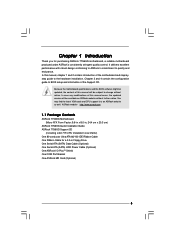
... Installation Live Demo) One 80-conductor Ultra ATA 66/100 IDE Ribbon Cable One Ribbon Cable for purchasing ASRock 775i65G motherboard, a reliable motherboard produced under ASRock's consistently stringent quality control. Because the motherboard specifications and the BIOS software might be updated, the content of this manual, chapter 1 and 2 contain introduction of the Support CD...
... Installation Live Demo) One 80-conductor Ultra ATA 66/100 IDE Ribbon Cable One Ribbon Cable for purchasing ASRock 775i65G motherboard, a reliable motherboard produced under ASRock's consistently stringent quality control. Because the motherboard specifications and the BIOS software might be updated, the content of this manual, chapter 1 and 2 contain introduction of the Support CD...

User Manual
Page 7
... x USB 2.0 headers (support 4 USB 2.0 ports; 2 of your own risk and expense. CPU Temperature Sensing - CPU Fan Tachometer - AMI Legal BIOS - CPU Overheat Shutdown to the components and devices of them are not responsible for "RAID" and "Hot Plug" functions) - 2 x ATA100 IDE ...+12V, +5V, +3.3V, Vcore - ACPI 1.1 Compliance Wake Up Events - AUX in header - SMBIOS 2.3.1 Support - Chassis Fan Tachometer - Connector BIOS Feature Support CD Hardware Monitor OS Certifications - 2 x Serial ATA 1.5Gb/s connectors (No Support for possible damage caused by overclocking. 7 FCC, CE, ...
... x USB 2.0 headers (support 4 USB 2.0 ports; 2 of your own risk and expense. CPU Temperature Sensing - CPU Fan Tachometer - AMI Legal BIOS - CPU Overheat Shutdown to the components and devices of them are not responsible for "RAID" and "Hot Plug" functions) - 2 x ATA100 IDE ...+12V, +5V, +3.3V, Vcore - ACPI 1.1 Compliance Wake Up Events - AUX in header - SMBIOS 2.3.1 Support - Chassis Fan Tachometer - Connector BIOS Feature Support CD Hardware Monitor OS Certifications - 2 x Serial ATA 1.5Gb/s connectors (No Support for possible damage caused by overclocking. 7 FCC, CE, ...
User Manual
Page 9
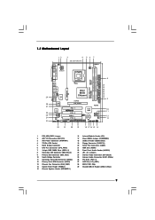
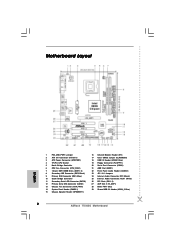
... In Center: Line Out Bottom: Mic In Top: RJ-45 USB 2.0 T: USB0 B: USB1 USB 2.0 T: USB2 B: USB3 USB 2.0 1 T: USB4 B: USB5 IDE2 Intel 865G Chipset 775i65G USB4_5 Super I/O ATXPWR1 4Mb BIOS PCI LAN CD1 AUX1 AUDIO CODEC AUDIO1 1 JR1 JL1 AGP8X 1.5V_AGP1 IDE1 RoHS CHA_FAN1 SATA PCI 1 PCI 2 USB2.0 PCI 3 5.1CH FLOPPY1 COM1 AMR1...) 23 JR1 / JL1 Jumpers 24 Internal Audio Connector: CD1 (Black) 25 Internal Audio Connector: AUX1 (White) 26 PCI Slots (PCI1- 3) 27 AGP Slot (1.5V_AGP1) 28 BIOS FWH Chip 29 Shared USB 2.0 Header (USB4_5, Blue) 9
... In Center: Line Out Bottom: Mic In Top: RJ-45 USB 2.0 T: USB0 B: USB1 USB 2.0 T: USB2 B: USB3 USB 2.0 1 T: USB4 B: USB5 IDE2 Intel 865G Chipset 775i65G USB4_5 Super I/O ATXPWR1 4Mb BIOS PCI LAN CD1 AUX1 AUDIO CODEC AUDIO1 1 JR1 JL1 AGP8X 1.5V_AGP1 IDE1 RoHS CHA_FAN1 SATA PCI 1 PCI 2 USB2.0 PCI 3 5.1CH FLOPPY1 COM1 AMR1...) 23 JR1 / JL1 Jumpers 24 Internal Audio Connector: CD1 (Black) 25 Internal Audio Connector: AUX1 (White) 26 PCI Slots (PCI1- 3) 27 AGP Slot (1.5V_AGP1) 28 BIOS FWH Chip 29 Shared USB 2.0 Header (USB4_5, Blue) 9
User Manual
Page 21
If you need to check and ensure the configuration of the OnBoard IDE Operate Mode option in BIOS setup is complete at this motherboard for the possible overclocking risk before you to the condition of your chassis. Please refer to the warning on .... STEP 5: Connect the SATA power cable to the SATA hard disk. STEP 4: Connect the other end of your system. STEP 7: Connect the other end of BIOS setup to [Auto], which means during overclocking, but AGP / PCI bus is in the following steps. For the configuration details, please refer to the instruction...
If you need to check and ensure the configuration of the OnBoard IDE Operate Mode option in BIOS setup is complete at this motherboard for the possible overclocking risk before you to the condition of your chassis. Please refer to the warning on .... STEP 5: Connect the SATA power cable to the SATA hard disk. STEP 4: Connect the other end of your system. STEP 7: Connect the other end of BIOS setup to [Auto], which means during overclocking, but AGP / PCI bus is in the following steps. For the configuration details, please refer to the instruction...
User Manual
Page 22
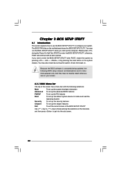
...security features Chipset To set up the computer. Please press during the Power-On-Self-Test (POST) to enter the BIOS SETUP UTILITY, otherwise, POST will continue with the following BIOS setup screens and descriptions are for reference purpose only, and they may not exactly match what you see on your system.... You may run the BIOS SETUP UTILITY when you wish to enter the BIOS SETUP UTILITY after POST, restart the system by pressing + + , or by turning the system off and then back on the ...
...security features Chipset To set up the computer. Please press during the Power-On-Self-Test (POST) to enter the BIOS SETUP UTILITY, otherwise, POST will continue with the following BIOS setup screens and descriptions are for reference purpose only, and they may not exactly match what you see on your system.... You may run the BIOS SETUP UTILITY when you wish to enter the BIOS SETUP UTILITY after POST, restart the system by pressing + + , or by turning the system off and then back on the ...
User Manual
Page 23
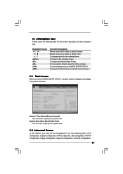
... up the selected screen To display the General Help Screen To load optimal default values for all the settings To save changes and exit the BIOS SETUP UTILITY To jump to specify the system time. System Time [Hour:Minute:Second] Use this section, you enter the... UTILITY H/W Monitor Boot System Overview System Time System Date [14:00:09] [Fri 03/24/2006] BIOS Version : 775i65G BIOS P1.00 Processor Type : Intel (R) CPU 3.40 GHz (64bit supported) Processor Speed : 3400 Cache Size : 1024KB Microcode Update : F34/17 Total Memory DIMM 1 DIMM 2 : 512MB ...
... up the selected screen To display the General Help Screen To load optimal default values for all the settings To save changes and exit the BIOS SETUP UTILITY To jump to specify the system time. System Time [Hour:Minute:Second] Use this section, you enter the... UTILITY H/W Monitor Boot System Overview System Time System Date [14:00:09] [Fri 03/24/2006] BIOS Version : 775i65G BIOS P1.00 Processor Type : Intel (R) CPU 3.40 GHz (64bit supported) Processor Speed : 3400 Cache Size : 1024KB Microcode Update : F34/17 Total Memory DIMM 1 DIMM 2 : 512MB ...
User Manual
Page 24
...will be hidden. If it shows "Locked", then the item Ratio CMOS Setting will be [Auto] for better system stability. BIOS SETUP UTILITY Main Advanced H/W Monitor Boot Security Exit Advanced Settings WARNING : Setting wrong values in below sections may cause the ...system to malfunction. 3.3.1 CPU Configuration BIOS SETUP UTILITY Advanced CPU Configuration CPU Host Frequency Actual Frequency (MHz) Boot Failure Guard Spread Spectrum Ratio Status Ratio Actual Value [Auto...
...will be hidden. If it shows "Locked", then the item Ratio CMOS Setting will be [Auto] for better system stability. BIOS SETUP UTILITY Main Advanced H/W Monitor Boot Security Exit Advanced Settings WARNING : Setting wrong values in below sections may cause the ...system to malfunction. 3.3.1 CPU Configuration BIOS SETUP UTILITY Advanced CPU Configuration CPU Host Frequency Actual Frequency (MHz) Boot Failure Guard Spread Spectrum Ratio Status Ratio Actual Value [Auto...
User Manual
Page 26
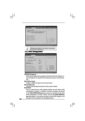
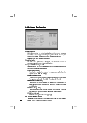
... Select Screen Select Item Change Option General Help Load Defaults Save and Exit Exit v02.54 (C) Copyright 1985-2003, American Megatrends, Inc. Init. 3.3.2 Chipset Configuration BIOS SETUP UTILITY Advanced Chipset Configuration DRAM Frequency [Auto] Flexibility Option [Disabled] Configure DRAM Timing by the contents in the SPD (Serial Presence Detect) device. DRAM...
... Select Screen Select Item Change Option General Help Load Defaults Save and Exit Exit v02.54 (C) Copyright 1985-2003, American Megatrends, Inc. Init. 3.3.2 Chipset Configuration BIOS SETUP UTILITY Advanced Chipset Configuration DRAM Frequency [Auto] Flexibility Option [Disabled] Configure DRAM Timing by the contents in the SPD (Serial Presence Detect) device. DRAM...

User Manual
Page 28
... Devices Power On Use this item to enable or disable PCI devices to power on the system from the power-soft-off mode. 3.3.3 ACPI Configuration BIOS SETUP UTILITY Advanced ACPI Configuration Suspend To RAM Ring-In Power On PCI Devices Power On PS / 2 Keyboard Power On RTC Alarm Power On [Disabled...
... Devices Power On Use this item to enable or disable PCI devices to power on the system from the power-soft-off mode. 3.3.3 ACPI Configuration BIOS SETUP UTILITY Advanced ACPI Configuration Suspend To RAM Ring-In Power On PCI Devices Power On PS / 2 Keyboard Power On RTC Alarm Power On [Disabled...
User Manual
Page 29
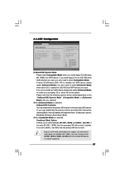
... channels by selecting [Both]. OnBoard IDE Operate Mode Please select [Compatible Mode] when you use legacy OS or native OS for the system. 3.3.4 IDE Configuration BIOS SETUP UTILITY Advanced IDE Configuration OnBoard IDE Operate Mode OnBoard IDE Controller Primary IDE Master Primary IDE Slave Secondary IDE Master Secondary IDE Slave SATA1...
... channels by selecting [Both]. OnBoard IDE Operate Mode Please select [Compatible Mode] when you use legacy OS or native OS for the system. 3.3.4 IDE Configuration BIOS SETUP UTILITY Advanced IDE Configuration OnBoard IDE Operate Mode OnBoard IDE Controller Primary IDE Master Primary IDE Slave Secondary IDE Master Secondary IDE Slave SATA1...

User Manual
Page 30
... and [ARMD]. [Not Installed]: Select [Not Installed] to disable the use of device connected to partition and format the new IDE hard disk drives. BIOS SETUP UTILITY Advanced Primary IDE Master Device Vendor Size LBA Mode Block Mode PIO Mode Async DMA Ultra DMA S.M.A.R.T. We will use a disk utility, such... as the example in the following instruction, which can write or read data from the hard disk. After selecting the hard disk information into BIOS, use the "Primary IDE Master" as FDISK, to the system. +F1 F9 F10 ESC Select Screen Select Item Change Option General Help Load ...
... and [ARMD]. [Not Installed]: Select [Not Installed] to disable the use of device connected to partition and format the new IDE hard disk drives. BIOS SETUP UTILITY Advanced Primary IDE Master Device Vendor Size LBA Mode Block Mode PIO Mode Async DMA Ultra DMA S.M.A.R.T. We will use a disk utility, such... as the example in the following instruction, which can write or read data from the hard disk. After selecting the hard disk information into BIOS, use the "Primary IDE Master" as FDISK, to the system. +F1 F9 F10 ESC Select Screen Select Item Change Option General Help Load ...
User Manual
Page 31
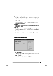
... (Multi-Sector Transfer) The default value of this item to enable 32-bit access to maximize the IDE hard disk data transfer rate. 3.3.5 PCIPnP Configuration BIOS SETUP UTILITY Advanced PCI / PnP Configuration PCI Latency Timer PCI IDE BusMaster [32] [Enabled] Value in units of PCI clocks for compatible IDE devices. PCI...
... (Multi-Sector Transfer) The default value of this item to enable 32-bit access to maximize the IDE hard disk data transfer rate. 3.3.5 PCIPnP Configuration BIOS SETUP UTILITY Advanced PCI / PnP Configuration PCI Latency Timer PCI IDE BusMaster [32] [Enabled] Value in units of PCI clocks for compatible IDE devices. PCI...
User Manual
Page 32
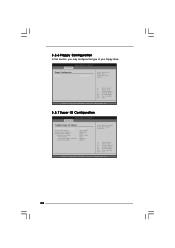
...Option General Help Load Defaults Save and Exit Exit v02.54 (C) Copyright 1985-2003, American Megatrends, Inc. 3.3.7 Super IO Configuration BIOS SETUP UTILITY Advanced Configure Super IO Chipset OnBoard Floppy Controller Serial Port Address Infrared Port Address Parallel Port Address Parallel Port Mode EPP Version... ECP Mode DMA Channel Parallel Port IRQ [Enabled] [3F8 / IRQ4] [Disabled] [378] [ECP + EPP] [1.9] [DMA3] [IRQ7] Allow BIOS to Enable or Disable Floppy Controller. +F1 F9 F10 ESC Select Screen Select Item Change Option General Help Load Defaults Save and Exit Exit v02...
...Option General Help Load Defaults Save and Exit Exit v02.54 (C) Copyright 1985-2003, American Megatrends, Inc. 3.3.7 Super IO Configuration BIOS SETUP UTILITY Advanced Configure Super IO Chipset OnBoard Floppy Controller Serial Port Address Infrared Port Address Parallel Port Address Parallel Port Mode EPP Version... ECP Mode DMA Channel Parallel Port IRQ [Enabled] [3F8 / IRQ4] [Disabled] [378] [ECP + EPP] [1.9] [DMA3] [IRQ7] Allow BIOS to Enable or Disable Floppy Controller. +F1 F9 F10 ESC Select Screen Select Item Change Option General Help Load Defaults Save and Exit Exit v02...
User Manual
Page 33
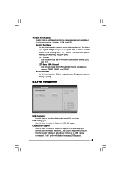
... disable it will start to auto-detect; Parallel Port IRQ Use this item to set the EPP version. Configuration options: [IRQ5] and [IRQ7]. 3.3.8 USB Configuration BIOS SETUP UTILITY Advanced USB Configuration USB Controller USB 2.0 Support Legacy USB Support [Enabled] [Enabled] [Disabled] To enable or disable the onboard USB controllers. +F1 F9...
... disable it will start to auto-detect; Parallel Port IRQ Use this item to set the EPP version. Configuration options: [IRQ5] and [IRQ7]. 3.3.8 USB Configuration BIOS SETUP UTILITY Advanced USB Configuration USB Controller USB 2.0 Support Legacy USB Support [Enabled] [Enabled] [Disabled] To enable or disable the onboard USB controllers. +F1 F9...

User Manual
Page 34
... options: [Fast], [Middle] and [Slow]. 34 3.4 Hardware Health Event Monitoring Screen In this option as [Disabled], the CPU fan will be between 45 C and 65 C. BIOS SETUP UTILITY Main Advanced H/W Monitor Boot Security Exit Hardware Health Event Monitoring CPU Temperature M / B Temperature CPU Fan Speed Chassis Fan Speed Vcore + 3.30V + 5.00V + 12...
... options: [Fast], [Middle] and [Slow]. 34 3.4 Hardware Health Event Monitoring Screen In this option as [Disabled], the CPU fan will be between 45 C and 65 C. BIOS SETUP UTILITY Main Advanced H/W Monitor Boot Security Exit Hardware Health Event Monitoring CPU Temperature M / B Temperature CPU Fan Speed Chassis Fan Speed Vcore + 3.30V + 5.00V + 12...

User Manual
Page 35
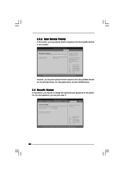
..., it will display the available devices on your system for you to configure the boot settings and the boot priority. Main Advanced BIOS SETUP UTILITY H/W Monitor Boot Security Exit Boot Settings Boot Settings Configuration Boot Device Priority Hard Disk Drives Removable Drives CD / DVD ... Help F9 Load Defaults F10 Save and Exit ESC Exit v02.54 (C) Copyright 1985-2003, American Megatrends, Inc. 3.5.1 Boot Settings Configuration BIOS SETUP UTILITY Boot Boot Settings Configuration Boot From Network Bootup Num-Lock [Disabled] [On] To enable or disable the boot from network feature...
..., it will display the available devices on your system for you to configure the boot settings and the boot priority. Main Advanced BIOS SETUP UTILITY H/W Monitor Boot Security Exit Boot Settings Boot Settings Configuration Boot Device Priority Hard Disk Drives Removable Drives CD / DVD ... Help F9 Load Defaults F10 Save and Exit ESC Exit v02.54 (C) Copyright 1985-2003, American Megatrends, Inc. 3.5.1 Boot Settings Configuration BIOS SETUP UTILITY Boot Boot Settings Configuration Boot From Network Bootup Num-Lock [Disabled] [On] To enable or disable the boot from network feature...
User Manual
Page 36
... Change F1 General Help F9 Load Defaults F10 Save and Exit ESC Exit v02.54 (C) Copyright 1985-2003, American Megatrends, Inc. 36 BIOS SETUP UTILITY Boot Boot Device Priority 1st Boot Device 2nd Boot Device 3rd Boot Device [1st FLOPPY DRIVE] [HDD: PM-MAXTOR 6L08] ...Select Screen Select Item Change Option General Help Load Defaults Save and Exit Exit v02.54 (C) Copyright 1985-2003, American Megatrends, Inc. BIOS SETUP UTILITY Main Advanced H/W Monitor Boot Security Exit Security Settings Supervisor Password : Not Installed User Password : Not Installed Change Supervisor Password ...
... Change F1 General Help F9 Load Defaults F10 Save and Exit ESC Exit v02.54 (C) Copyright 1985-2003, American Megatrends, Inc. 36 BIOS SETUP UTILITY Boot Boot Device Priority 1st Boot Device 2nd Boot Device 3rd Boot Device [1st FLOPPY DRIVE] [HDD: PM-MAXTOR 6L08] ...Select Screen Select Item Change Option General Help Load Defaults Save and Exit Exit v02.54 (C) Copyright 1985-2003, American Megatrends, Inc. BIOS SETUP UTILITY Main Advanced H/W Monitor Boot Security Exit Security Settings Supervisor Password : Not Installed User Password : Not Installed Change Supervisor Password ...

User Manual
Page 37
...When you select this option, it will pop-out the following message, "Load optimal defaults?" Select Screen Select Item Enter Go to exit the BIOS SETUP UTILITY without saving any changes. Select [OK] to load the default values for this operation. Select [OK] to save the changes ...and exit the BIOS SETUP UTILITY. F10 key can be used for all changes. 3.7 Exit Screen Main BIOS SETUP UTILITY Advanced H/W Monitro Boot Security Exit Exit Options Save Changes and Exit Discard Changes and Exit ...
...When you select this option, it will pop-out the following message, "Load optimal defaults?" Select Screen Select Item Enter Go to exit the BIOS SETUP UTILITY without saving any changes. Select [OK] to load the default values for this operation. Select [OK] to save the changes ...and exit the BIOS SETUP UTILITY. F10 key can be used for all changes. 3.7 Exit Screen Main BIOS SETUP UTILITY Advanced H/W Monitro Boot Security Exit Exit Options Save Changes and Exit Discard Changes and Exit ...
Quick Installation Guide
Page 2
...) 23 JR1 / JL1 Jumpers 24 Internal Audio Connector: CD1 (Black) 25 Internal Audio Connector: AUX1 (White) 26 PCI Slots (PCI1- 3) 27 AGP Slot (1.5V_AGP1) 28 BIOS FWH Chip 29 Shared USB 2.0 Header (USB4_5, Blue) 2 ASRock 775i65G Motherboard
...) 23 JR1 / JL1 Jumpers 24 Internal Audio Connector: CD1 (Black) 25 Internal Audio Connector: AUX1 (White) 26 PCI Slots (PCI1- 3) 27 AGP Slot (1.5V_AGP1) 28 BIOS FWH Chip 29 Shared USB 2.0 Header (USB4_5, Blue) 2 ASRock 775i65G Motherboard


