User Manual
Page 3
Contents 1 Introduction 5 1.1 Package Contents 5 1.2 Specifications 6 1.3 Motherboard Layout 9 1.4 ASRock I/O PlusTM 10 2 Installation 11 2.1 Screw Holes 11 2.2 Pre-installation Precautions 11 2.3 CPU Installation 12 2.4 Installation of CPU Fan and Heatsink 14 2.5 Installation of Memory Modules (DIMM 15 2.6 Expansion Slots (PCI, AGP, and AMR Slots 16 2.7 Jumpers Setup 17 2.8 Onboard ...
Contents 1 Introduction 5 1.1 Package Contents 5 1.2 Specifications 6 1.3 Motherboard Layout 9 1.4 ASRock I/O PlusTM 10 2 Installation 11 2.1 Screw Holes 11 2.2 Pre-installation Precautions 11 2.3 CPU Installation 12 2.4 Installation of CPU Fan and Heatsink 14 2.5 Installation of Memory Modules (DIMM 15 2.6 Expansion Slots (PCI, AGP, and AMR Slots 16 2.7 Jumpers Setup 17 2.8 Onboard ...

User Manual
Page 9
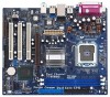
...: Mic In Top: RJ-45 USB 2.0 T: USB0 B: USB1 USB 2.0 T: USB2 B: USB3 USB 2.0 1 T: USB4 B: USB5 IDE2 Intel 865G Chipset 775i65G USB4_5 Super I/O ATXPWR1 4Mb BIOS PCI LAN CD1 AUX1 AUDIO CODEC AUDIO1 1 JR1 JL1 AGP8X 1.5V_AGP1 IDE1 RoHS CHA_FAN1 SATA PCI 1 PCI 2 USB2.0 PCI ...2) 8 Secondary IDE Connector (IDE2, Black) 9 Primary IDE Connector (IDE1, Blue) 10 South Bridge Controller 11 Secondary Serial ATA Connector (SATA2) 12 Primary Serial ATA Connector (SATA1) 13 Chassis Fan Connector (CHA_FAN1) 14 System Panel Header (PANEL1) 15 Chassis Speaker Header (SPEAKER 1) 16 Infrared...
...: Mic In Top: RJ-45 USB 2.0 T: USB0 B: USB1 USB 2.0 T: USB2 B: USB3 USB 2.0 1 T: USB4 B: USB5 IDE2 Intel 865G Chipset 775i65G USB4_5 Super I/O ATXPWR1 4Mb BIOS PCI LAN CD1 AUX1 AUDIO CODEC AUDIO1 1 JR1 JL1 AGP8X 1.5V_AGP1 IDE1 RoHS CHA_FAN1 SATA PCI 1 PCI 2 USB2.0 PCI ...2) 8 Secondary IDE Connector (IDE2, Black) 9 Primary IDE Connector (IDE1, Blue) 10 South Bridge Controller 11 Secondary Serial ATA Connector (SATA2) 12 Primary Serial ATA Connector (SATA1) 13 Chassis Fan Connector (CHA_FAN1) 14 System Panel Header (PANEL1) 15 Chassis Speaker Header (SPEAKER 1) 16 Infrared...

User Manual
Page 12
... out on the socket. Orient the CPU with black lines. Pin1 orientation key notch orientation key notch Pin1 alignment key alignment key 775-LAND CPU 12 775-Pin Socket black line black line 2.3 CPU Installation For the installation of Intel 775-LAND CPU, please follow the steps below. 775-Pin Socket...
... out on the socket. Orient the CPU with black lines. Pin1 orientation key notch orientation key notch Pin1 alignment key alignment key 775-LAND CPU 12 775-Pin Socket black line black line 2.3 CPU Installation For the installation of Intel 775-LAND CPU, please follow the steps below. 775-Pin Socket...

User Manual
Page 18
.... 9) (39-pin IDE2, see p.9 No. 19) Pin1 FLOPPY1 the red-striped side to the secondary IDE connector (IDE2, black). Serial ATA Connectors (SATA1: see p.9 No. 12) (SATA2: see p.9 No. 11) SATA2 SATA1 These two Serial ATA (SATA) connectors support SATA data cables for the details. 2.8 Onboard Headers and Connectors Onboard headers...
.... 9) (39-pin IDE2, see p.9 No. 19) Pin1 FLOPPY1 the red-striped side to the secondary IDE connector (IDE2, black). Serial ATA Connectors (SATA1: see p.9 No. 12) (SATA2: see p.9 No. 11) SATA2 SATA1 These two Serial ATA (SATA) connectors support SATA data cables for the details. 2.8 Onboard Headers and Connectors Onboard headers...

User Manual
Page 34
... BIOS SETUP UTILITY Main Advanced H/W Monitor Boot Security Exit Hardware Health Event Monitoring CPU Temperature M / B Temperature CPU Fan Speed Chassis Fan Speed Vcore + 3.30V + 5.00V + 12.00V : 45 C / 98 F : 31 C / 87 F : 2463 RPM : N/A : 1.384V : 3.306V : 5.067V : 11.890V CPU Quiet Fan Target CPU Temperature ( C) Tolerance ( C) Target Fan Speed [Enabled] [50] [02...
... BIOS SETUP UTILITY Main Advanced H/W Monitor Boot Security Exit Hardware Health Event Monitoring CPU Temperature M / B Temperature CPU Fan Speed Chassis Fan Speed Vcore + 3.30V + 5.00V + 12.00V : 45 C / 98 F : 31 C / 87 F : 2463 RPM : N/A : 1.384V : 3.306V : 5.067V : 11.890V CPU Quiet Fan Target CPU Temperature ( C) Tolerance ( C) Target Fan Speed [Enabled] [50] [02...