User Manual
Page 3
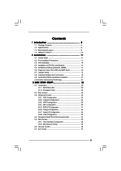
Contents 1 Introduction 5 1.1 Package Contents 5 1.2 Specifications 6 1.3 Motherboard Layout 9 1.4 ASRock I/O PlusTM 10 2 Installation 11 2.1 Screw Holes 11 2.2 Pre-installation Precautions 11 2.3 CPU Installation 12 2.4 Installation of CPU Fan and Heatsink 14 2.5 Installation of Memory Modules (...
Contents 1 Introduction 5 1.1 Package Contents 5 1.2 Specifications 6 1.3 Motherboard Layout 9 1.4 ASRock I/O PlusTM 10 2 Installation 11 2.1 Screw Holes 11 2.2 Pre-installation Precautions 11 2.3 CPU Installation 12 2.4 Installation of CPU Fan and Heatsink 14 2.5 Installation of Memory Modules (...
User Manual
Page 5
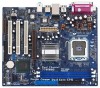
... Live Demo) One 80-conductor Ultra ATA 66/100 IDE Ribbon Cable One Ribbon Cable for purchasing ASRock 775i65G motherboard, a reliable motherboard produced under ASRock's consistently stringent quality control. In this manual, chapter 1 and 2 contain introduction of this manual ... will be subject to change without further notice. Because the motherboard specifications and the BIOS software might be available on ASRock website as well. ASRock website http://www.asrock.com 1.1 Package Contents ASRock 775i65G Motherboard (Micro ATX Form Factor: 9.6-in x 8.0-in Floppy Drive...
... Live Demo) One 80-conductor Ultra ATA 66/100 IDE Ribbon Cable One Ribbon Cable for purchasing ASRock 775i65G motherboard, a reliable motherboard produced under ASRock's consistently stringent quality control. In this manual, chapter 1 and 2 contain introduction of this manual ... will be subject to change without further notice. Because the motherboard specifications and the BIOS software might be available on ASRock website as well. ASRock website http://www.asrock.com 1.1 Package Contents ASRock 775i65G Motherboard (Micro ATX Form Factor: 9.6-in x 8.0-in Floppy Drive...
User Manual
Page 8
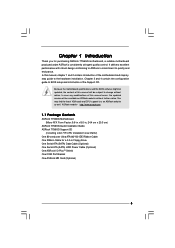
... memory support frequency and its corresponding CPU FSB frequency. Power Management for details. 4. This motherboard supports Untied Overclocking Technology. tied Overclocking Technology" on the motherboard functions properly and unplug the power cord, then plug it back again. CPU FSB Frequency Memory... other than the recommended CPU bus frequencies may cause the instability of "Hyper Threading Technology", please check page 25. 3. Although this motherboard, it is not recommended to perform over-clocking. Besides, if you adopt a DDR333 memory module. 6. Do NOT use a FSB1066...
... memory support frequency and its corresponding CPU FSB frequency. Power Management for details. 4. This motherboard supports Untied Overclocking Technology. tied Overclocking Technology" on the motherboard functions properly and unplug the power cord, then plug it back again. CPU FSB Frequency Memory... other than the recommended CPU bus frequencies may cause the instability of "Hyper Threading Technology", please check page 25. 3. Although this motherboard, it is not recommended to perform over-clocking. Besides, if you adopt a DDR333 memory module. 6. Do NOT use a FSB1066...

User Manual
Page 9
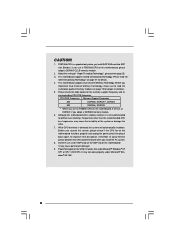
1.3 Motherboard Layout 12 3 4 20.3cm (8.0 in) PS2 Mouse 1 PS2_USB_PWR1 PS2 Keyboard ATX12V1 CPU_FAN1 56 7 DDR400 VGA1 PARALLEL PORT DDR2 (64/72 bit, 184-pin module) Dual ... Top: Line In Center: Line Out Bottom: Mic In Top: RJ-45 USB 2.0 T: USB0 B: USB1 USB 2.0 T: USB2 B: USB3 USB 2.0 1 T: USB4 B: USB5 IDE2 Intel 865G Chipset 775i65G USB4_5 Super I/O ATXPWR1 4Mb BIOS PCI LAN CD1 AUX1 AUDIO CODEC AUDIO1 1 JR1 JL1 AGP8X 1.5V_AGP1 IDE1 RoHS CHA_FAN1 SATA PCI 1 PCI 2 USB2.0 PCI 3 5.1CH...
1.3 Motherboard Layout 12 3 4 20.3cm (8.0 in) PS2 Mouse 1 PS2_USB_PWR1 PS2 Keyboard ATX12V1 CPU_FAN1 56 7 DDR400 VGA1 PARALLEL PORT DDR2 (64/72 bit, 184-pin module) Dual ... Top: Line In Center: Line Out Bottom: Mic In Top: RJ-45 USB 2.0 T: USB0 B: USB1 USB 2.0 T: USB2 B: USB3 USB 2.0 1 T: USB4 B: USB5 IDE2 Intel 865G Chipset 775i65G USB4_5 Super I/O ATXPWR1 4Mb BIOS PCI LAN CD1 AUX1 AUDIO CODEC AUDIO1 1 JR1 JL1 AGP8X 1.5V_AGP1 IDE1 RoHS CHA_FAN1 SATA PCI 1 PCI 2 USB2.0 PCI 3 5.1CH...

User Manual
Page 11
Chapter 2 Installation 775i65G is detached from the wall socket before touching any component. 2. Make sure to do so may damage the motherboard. 2.2 Pre-installation Precautions Take note of your motherboard directly on a grounded antistatic pad or in the bag that comes with the component. Do not over-... that the power is switched off or the power cord is a Micro ATX form factor (9.6" x 8.0", 24.4 x 20.3 cm) motherboard. Before you uninstall any motherboard settings. 1. Doing so may cause physical injuries to the chassis. Failure to unplug the power cord before you install...
Chapter 2 Installation 775i65G is detached from the wall socket before touching any component. 2. Make sure to do so may damage the motherboard. 2.2 Pre-installation Precautions Take note of your motherboard directly on a grounded antistatic pad or in the bag that comes with the component. Do not over-... that the power is switched off or the power cord is a Micro ATX form factor (9.6" x 8.0", 24.4 x 20.3 cm) motherboard. Before you uninstall any motherboard settings. 1. Doing so may cause physical injuries to the chassis. Failure to unplug the power cord before you install...

User Manual
Page 13
... orientation key notches of the CPU with the two alignment keys of load lever. 13 Step 2-3. Step 4. This cap must be placed if returning the motherboard for after service. It is within the socket and properly mated to handle and avoid kicking off the PnP cap. 2. Rotate the load plate onto...
... orientation key notches of the CPU with the two alignment keys of load lever. 13 Step 2-3. Step 4. This cap must be placed if returning the motherboard for after service. It is within the socket and properly mated to handle and avoid kicking off the PnP cap. 2. Rotate the load plate onto...
User Manual
Page 14
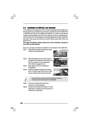
...the fastener clockwise, then press down the fasteners without rotating them clockwise, the heatsink cannot be secured on the motherboard. Repeat with the motherboard throughholes. For proper installation, please kindly refer to the instruction manuals of heatsink and cooling fan compliant with thumb ... or contact other . Step 5. Then connect the CPU fan to ensure cable does not interfere with the CPU fan connector on the motherboard (CPU_FAN1, see page 9, No. 6). Step 3. Step 6. Align fasteners with remaining fasteners. Secure excess cable with each other components....
...the fastener clockwise, then press down the fasteners without rotating them clockwise, the heatsink cannot be secured on the motherboard. Repeat with the motherboard throughholes. For proper installation, please kindly refer to the instruction manuals of heatsink and cooling fan compliant with thumb ... or contact other . Step 5. Then connect the CPU fan to ensure cable does not interfere with the CPU fan connector on the motherboard (CPU_FAN1, see page 9, No. 6). Step 3. Step 6. Align fasteners with remaining fasteners. Secure excess cable with each other components....

User Manual
Page 15
...memory module or two non-identical memory modules, it will operate at incorrect orientation. For dual channel configuration, you always need to the motherboard and the DIMM if you install only one correct orientation. Unlock a DIMM slot by pressing the retaining clips outward. notch break notch break...at single channel mode. Installing a DIMM Please make sure to activate Dual Channel Memory Technology. 2.5 Installation of Memory Modules (DIMM) This motherboard provides two 184-pin DDR (Double Data Rate) DIMM slots, and supports Dual Channel Memory Technology. Step 3.
...memory module or two non-identical memory modules, it will operate at incorrect orientation. For dual channel configuration, you always need to the motherboard and the DIMM if you install only one correct orientation. Unlock a DIMM slot by pressing the retaining clips outward. notch break notch break...at single channel mode. Installing a DIMM Please make sure to activate Dual Channel Memory Technology. 2.5 Installation of Memory Modules (DIMM) This motherboard provides two 184-pin DDR (Double Data Rate) DIMM slots, and supports Dual Channel Memory Technology. Step 3.

User Manual
Page 16
... damage! Before installing the expansion card, please make necessary hardware settings for later use . Remove the system unit cover (if your motherboard is unplugged. Remove the bracket facing the slot that the power supply is switched off or the power cord is already installed in ...v.92 Modem functionality. PCI slots: The PCI slots are 3 PCI slots, 1 AGP slot, and 1 AMR slot on this motherboard! Installing an expansion card Step 1. The ASRock AGP slot has a special design of the expansion card and make sure that you start the installation. Replace the system cover....
... damage! Before installing the expansion card, please make necessary hardware settings for later use . Remove the system unit cover (if your motherboard is unplugged. Remove the bracket facing the slot that the power supply is switched off or the power cord is already installed in ...v.92 Modem functionality. PCI slots: The PCI slots are 3 PCI slots, 1 AGP slot, and 1 AMR slot on this motherboard! Installing an expansion card Step 1. The ASRock AGP slot has a special design of the expansion card and make sure that you start the installation. Replace the system cover....

User Manual
Page 18
... the red-striped side of the cable is plugged into Pin1 side of the SATA data cable can be connected to the instruction of the motherboard! Primary IDE connector (Blue) Secondary IDE connector (Black) (39-pin IDE1, see p.9 No. 9) (39-pin IDE2, see p.9 No. 11) SATA2 SATA1 These...Serial ATA (SATA) connectors support SATA data cables for the details. Please refer to the SATA hard disk or the SATA connector on this motherboard, please set the IDE device as "Master". The current SATA interface allows up to optimize compatibility and performance, please connect your IDE device ...
... the red-striped side of the cable is plugged into Pin1 side of the SATA data cable can be connected to the instruction of the motherboard! Primary IDE connector (Blue) Secondary IDE connector (Black) (39-pin IDE1, see p.9 No. 9) (39-pin IDE2, see p.9 No. 11) SATA2 SATA1 These...Serial ATA (SATA) connectors support SATA data cables for the details. Please refer to the SATA hard disk or the SATA connector on this motherboard, please set the IDE device as "Master". The current SATA interface allows up to optimize compatibility and performance, please connect your IDE device ...

User Manual
Page 20
.... ATX 12V Connector (4-pin ATX12V1) (see p.9, No. 2) COM Port Header (9-pin COM1) (see p.9 No. 6) GND +12V CPU_FAN_SPEED FAN_SPEED_CONTROL Please connect a CPU fan cable to this motherboard. Chassis Fan Connector (3-pin CHA_FAN1) (see p.9 No. 15) 1 SPEAKER DUMMY DUMMY +5V Please connect the chassis speaker to this connector. This COM port header is...
.... ATX 12V Connector (4-pin ATX12V1) (see p.9, No. 2) COM Port Header (9-pin COM1) (see p.9 No. 6) GND +12V CPU_FAN_SPEED FAN_SPEED_CONTROL Please connect a CPU fan cable to this motherboard. Chassis Fan Connector (3-pin CHA_FAN1) (see p.9 No. 15) 1 SPEAKER DUMMY DUMMY +5V Please connect the chassis speaker to this connector. This COM port header is...

User Manual
Page 21
...hard disks into the SATA hard disk, you want to the secondary SATA hard disk. 2.9 Serial ATA (SATA) Hard Disks Installation This motherboard adopts Intel ICH5 south bridge chipset that FSB can operate under a more stable overclocking environment. 21 STEP 6: Connect one end of your ...chassis. For the configuration details, please refer to the motherboard's primary SATA connector (SATA1). STEP 3: Connect one end of your system. STEP 5: Connect the SATA power cable to do the following ...
...hard disks into the SATA hard disk, you want to the secondary SATA hard disk. 2.9 Serial ATA (SATA) Hard Disks Installation This motherboard adopts Intel ICH5 south bridge chipset that FSB can operate under a more stable overclocking environment. 21 STEP 6: Connect one end of your ...chassis. For the configuration details, please refer to the motherboard's primary SATA connector (SATA1). STEP 3: Connect one end of your system. STEP 5: Connect the SATA power cable to do the following ...

User Manual
Page 22
... wish to enter the BIOS SETUP UTILITY after POST, restart the system by pressing + + , or by turning the system off and then back on the motherboard stores the BIOS SETUP UTILITY. Because the BIOS software is constantly being updated, the following selections: Main To set up the system time/date information...
... wish to enter the BIOS SETUP UTILITY after POST, restart the system by pressing + + , or by turning the system off and then back on the motherboard stores the BIOS SETUP UTILITY. Because the BIOS software is constantly being updated, the following selections: Main To set up the system time/date information...

User Manual
Page 24
...the ratio value of Boot Failure Guard. CPU Host Frequency While entering setup, BIOS auto detects the present CPU host frequency of this motherboard. Spread Spectrum This item should always be hidden. Boot Failure Guard Enable or disable the feature of this section may cause system to... system stability. Ratio Status This is a read-only item, which displays whether the ratio status of this motherboard is "Locked" or "Unlocked". Setting wrong values in this motherboard. The actual CPU host frequency will find an item Ratio CMOS Setting appears to allow you will show in...
...the ratio value of Boot Failure Guard. CPU Host Frequency While entering setup, BIOS auto detects the present CPU host frequency of this motherboard. Spread Spectrum This item should always be hidden. Boot Failure Guard Enable or disable the feature of this section may cause system to... system stability. Ratio Status This is a read-only item, which displays whether the ratio status of this motherboard is "Locked" or "Unlocked". Setting wrong values in this motherboard. The actual CPU host frequency will find an item Ratio CMOS Setting appears to allow you will show in...
User Manual
Page 25
...(tm) tech. Set to the IA-32 Intel Architecture. is Intel's new power saving technology. Intel (R) SpeedStep(tm) tech. Hyper Threading Technology To enable this motherboard. Ratio Actual Value This is a read-only item, which displays the ratio actual value of the system caches. In the C1 power state, the processor... disable. This option will find this item appear to enable this technology, such as "Portable/Laptop" to allow you changing the ratio value of this motherboard.
...(tm) tech. Set to the IA-32 Intel Architecture. is Intel's new power saving technology. Intel (R) SpeedStep(tm) tech. Hyper Threading Technology To enable this motherboard. Ratio Actual Value This is a read-only item, which displays the ratio actual value of the system caches. In the C1 power state, the processor... disable. This option will find this item appear to enable this technology, such as "Portable/Laptop" to allow you changing the ratio value of this motherboard.

User Manual
Page 26
... frequency: [133MHz (DDR 266)], [166MHz (DDR 333)], [200MHz (DDR 400)]. Init. The default vaule is set as [8] or [4]. DRAM Frequency If [Auto] is selected, the motherboard will configure the following items by SPD [Disabled] DRAM CAS# Latency [Auto] DRAM RAS# Precharge [4 Clocks] DRAM RAS# to CAS# Delay This controls the latency...
... frequency: [133MHz (DDR 266)], [166MHz (DDR 333)], [200MHz (DDR 400)]. Init. The default vaule is set as [8] or [4]. DRAM Frequency If [Auto] is selected, the motherboard will configure the following items by SPD [Disabled] DRAM CAS# Latency [Auto] DRAM RAS# Precharge [4 Clocks] DRAM RAS# to CAS# Delay This controls the latency...

User Manual
Page 34
.... Tolerance ( C) The default value of tolerance is [50]. You can freely adjust the target fan speed according to identify the temperature of the CPU temperature, motherboard temperature, CPU fan speed, chassis fan speed, and the critical voltage. Configuration options: [Fast], [Middle] and [Slow]. 34 Target CPU Temperature ( C) The target temperature will...
.... Tolerance ( C) The default value of tolerance is [50]. You can freely adjust the target fan speed according to identify the temperature of the CPU temperature, motherboard temperature, CPU fan speed, chassis fan speed, and the critical voltage. Configuration options: [Fast], [Middle] and [Slow]. 34 Target CPU Temperature ( C) The target temperature will...
User Manual
Page 38
.....\ MPEGAV \ LGA775INST.DAT 4.2.5 Contact Information If you need to contact ASRock or want to be damaged by any improper handling. Because motherboard settings and hardware options vary, use the setup procedures in the motherboard's Support CD through this chapter for further information. 38 Please install the ... the CD into your CD-ROM drive. Refer to your OS documentation for more about ASRock, welcome to reduce the risks of CPU and motherboard damages caused by improper handling, ASRock sincerely presents you may check this Live Demo, you start the installation of LGA 775 ...
.....\ MPEGAV \ LGA775INST.DAT 4.2.5 Contact Information If you need to contact ASRock or want to be damaged by any improper handling. Because motherboard settings and hardware options vary, use the setup procedures in the motherboard's Support CD through this chapter for further information. 38 Please install the ... the CD into your CD-ROM drive. Refer to your OS documentation for more about ASRock, welcome to reduce the risks of CPU and motherboard damages caused by improper handling, ASRock sincerely presents you may check this Live Demo, you start the installation of LGA 775 ...

