User Manual
Page 3
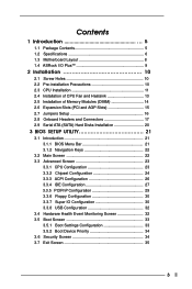
Contents 1 Introduction 5 1.1 Package Contents 5 1.2 Specifications 6 1.3 Motherboard Layout 8 1.4 ASRock I/O PlusTM 9 2 Installation 10 2.1 Screw Holes 10 2.2 Pre-installation Precautions 10 2.3 CPU Installation 11 2.4 Installation of CPU Fan and Heatsink 13 2.5 Installation of Memory Modules (DIMM ...
Contents 1 Introduction 5 1.1 Package Contents 5 1.2 Specifications 6 1.3 Motherboard Layout 8 1.4 ASRock I/O PlusTM 9 2 Installation 10 2.1 Screw Holes 10 2.2 Pre-installation Precautions 10 2.3 CPU Installation 11 2.4 Installation of CPU Fan and Heatsink 13 2.5 Installation of Memory Modules (DIMM ...
User Manual
Page 5
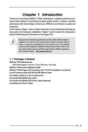
... modifications of this manual will be subject to BIOS setup and information of the Support CD. ASRock website http://www.asrock.com 1.1 Package Contents ASRock 775i48 Motherboard (ATX Form Factor: 12.0-in x 7.2-in, 30.5 cm x 18.3 cm) ASRock 775i48 Quick Installation Guide ASRock 775i48 Support CD (including LGA 775 CPU Installation Live Demo) One 80-conductor Ultra ATA 66...
... modifications of this manual will be subject to BIOS setup and information of the Support CD. ASRock website http://www.asrock.com 1.1 Package Contents ASRock 775i48 Motherboard (ATX Form Factor: 12.0-in x 7.2-in, 30.5 cm x 18.3 cm) ASRock 775i48 Quick Installation Guide ASRock 775i48 Support CD (including LGA 775 CPU Installation Live Demo) One 80-conductor Ultra ATA 66...

User Manual
Page 7
...7) Microsoft® Windows® 98 SE / ME / 2000 / XP compliant CAUTION! 1. However, if you use an FSB800-CPU on this motherboard! About the setting of FSB1 is detected, the system will run at DDR320 if you have adjusted the jumpers correctly. Power Management for USB 2.0 works... below for the memory support frequency and its corresponding CPU FSB frequency. To support FSB1066, please use a 3.3V AGP card on the motherboard functions properly and unplug the power cord, then plug it will automatically shutdown. Before you install the PC system. 5. Before installing FSB1066 ...
...7) Microsoft® Windows® 98 SE / ME / 2000 / XP compliant CAUTION! 1. However, if you use an FSB800-CPU on this motherboard! About the setting of FSB1 is detected, the system will run at DDR320 if you have adjusted the jumpers correctly. Power Management for USB 2.0 works... below for the memory support frequency and its corresponding CPU FSB frequency. To support FSB1066, please use a 3.3V AGP card on the motherboard functions properly and unplug the power cord, then plug it will automatically shutdown. Before you install the PC system. 5. Before installing FSB1066 ...

User Manual
Page 8
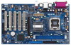
1.3 Motherboard Layout 12 34 5 18.3cm (7.2 in) PS2 Mouse Ps2 Keyboard 1 PS2_USB_PWR1 ATX12V1 PARALLEL PORT COM1 FSB800 DDR1 (64/72 bit, 184-pin module) DDR2 (64/... B: USB5 CPU_FAN1 USB4_5 ATXPWR1 Intel 848P Chipset Super I/O IDE1 1 FSB1 AGP 8X 1.5V_AGP1 2Mb BIOS LAN PHY Audio CODEC JR1 JL1 1 AUDIO1 AUX1 CD1 PCI 1 775i48 PCI 2 PCI 3 5.1 CH USB2.0 PCI 4 PCI 5 GAME1 FLOPPY1 Intel ICH5 SATA1 SATA2 CMOS Battery S ATA CLRCMOS0 1 USB67 CHA_FAN1 1 IR1 1 SPEAKER1 PLED PWRBTN 1 HDLED RESET PANEL...
1.3 Motherboard Layout 12 34 5 18.3cm (7.2 in) PS2 Mouse Ps2 Keyboard 1 PS2_USB_PWR1 ATX12V1 PARALLEL PORT COM1 FSB800 DDR1 (64/72 bit, 184-pin module) DDR2 (64/... B: USB5 CPU_FAN1 USB4_5 ATXPWR1 Intel 848P Chipset Super I/O IDE1 1 FSB1 AGP 8X 1.5V_AGP1 2Mb BIOS LAN PHY Audio CODEC JR1 JL1 1 AUDIO1 AUX1 CD1 PCI 1 775i48 PCI 2 PCI 3 5.1 CH USB2.0 PCI 4 PCI 5 GAME1 FLOPPY1 Intel ICH5 SATA1 SATA2 CMOS Battery S ATA CLRCMOS0 1 USB67 CHA_FAN1 1 IR1 1 SPEAKER1 PLED PWRBTN 1 HDLED RESET PANEL...
User Manual
Page 10
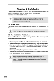
... switched off or the power cord is an ATX form factor (12.0" x 7.2", 30.5 x 18.3 cm) motherboard. Chapter 2 Installation 775i48 is detached from the wall socket before touching any motherboard settings. 1. Unplug the power cord from the power supply. To avoid damaging the motherboard components due to static electricity, NEVER place your chassis to the...
... switched off or the power cord is an ATX form factor (12.0" x 7.2", 30.5 x 18.3 cm) motherboard. Chapter 2 Installation 775i48 is detached from the wall socket before touching any motherboard settings. 1. Unplug the power cord from the power supply. To avoid damaging the motherboard components due to static electricity, NEVER place your chassis to the...
User Manual
Page 13
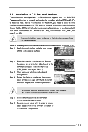
...page 8, No. 27). Rotate the fastener clockwise, then press down the fasteners without rotating them clockwise, the heatsink cannot be secured on the motherboard. Connect fan header with 775-Pin socket that the CPU and the heatsink are oriented on side closest to the CPU_FAN connector (CPU_FAN1, see ...page 8, No. 27). 2.4 Installation of CPU Fan and Heatsink This motherboard is an example to dissipate heat. Step 5. Please adopt the type of your CPU fan and heatsink. Step 4. If you need to spray ...
...page 8, No. 27). Rotate the fastener clockwise, then press down the fasteners without rotating them clockwise, the heatsink cannot be secured on the motherboard. Connect fan header with 775-Pin socket that the CPU and the heatsink are oriented on side closest to the CPU_FAN connector (CPU_FAN1, see ...page 8, No. 27). 2.4 Installation of CPU Fan and Heatsink This motherboard is an example to dissipate heat. Step 5. Please adopt the type of your CPU fan and heatsink. Step 4. If you need to spray ...
User Manual
Page 14
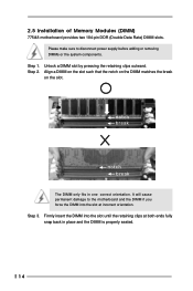
... disconnect power supply before adding or removing DIMMs or the system components. 2.5 Installation of Memory Modules (DIMM) 775i48 motherboard provides two 184-pin DDR (Double Data Rate) DIMM slots. Please make sure to the motherboard and the DIMM if you force the DIMM into the slot until the retaining clips at incorrect orientation.
... disconnect power supply before adding or removing DIMMs or the system components. 2.5 Installation of Memory Modules (DIMM) 775i48 motherboard provides two 184-pin DDR (Double Data Rate) DIMM slots. Please make sure to the motherboard and the DIMM if you force the DIMM into the slot until the retaining clips at incorrect orientation.
User Manual
Page 15
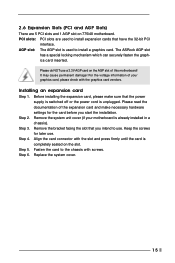
... Keep the screws for the card before you intend to use. Step 5. PCI slots: PCI slots are 5 PCI slots and 1 AGP slot on 775i48 motherboard. Step 4. Step 6. 2.6 Expansion Slots (PCI and AGP Slots) There are used to the chassis with screws. Installing an expansion card Step 1. ...expansion cards that you start the installation. Step 2. Remove the bracket facing the slot that have the 32-bit PCI interface. The ASRock AGP slot has a special locking mechanism which can securely fasten the graphics card inserted. Before installing the expansion card, please make necessary...
... Keep the screws for the card before you intend to use. Step 5. PCI slots: PCI slots are 5 PCI slots and 1 AGP slot on 775i48 motherboard. Step 4. Step 6. 2.6 Expansion Slots (PCI and AGP Slots) There are used to the chassis with screws. Installing an expansion card Step 1. ...expansion cards that you start the installation. Step 2. Remove the bracket facing the slot that have the 32-bit PCI interface. The ASRock AGP slot has a special locking mechanism which can securely fasten the graphics card inserted. Before installing the expansion card, please make necessary...
User Manual
Page 17
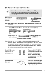
... FLOPPY1 the red-striped side to the IDE devices 80-conductor ATA 66/100 cable Note: If you use only one IDE device on the motherboard. 17 FDD connector (33-pin FLOPPY1) (see p.8 No. 6) PIN1 IDE1 PIN1 IDE2 connect the blue end connect the black end to the... motherboard to Pin1 Note: Make sure the red-striped side of the cable is plugged into Pin1 side of your hard disk drive to the primary ...
... FLOPPY1 the red-striped side to the IDE devices 80-conductor ATA 66/100 cable Note: If you use only one IDE device on the motherboard. 17 FDD connector (33-pin FLOPPY1) (see p.8 No. 6) PIN1 IDE1 PIN1 IDE2 connect the blue end connect the black end to the... motherboard to Pin1 Note: Make sure the red-striped side of the cable is plugged into Pin1 side of your hard disk drive to the primary ...
User Manual
Page 20
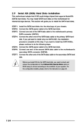
... SATA HDDs, please continue to the instruction on this step. STEP 3: Connect one SATA HDD, the installation process is correct according to the motherboard's primary SATA connector (SATA1). If you need to check and ensure the configuration of the OnBoard IDE Operate Mode option in BIOS setup is ...complete at this motherboard for internal storage devices. STEP 5: Connect the SATA power cable to the SATA hard disk. STEP 7: Connect the other end of the second...
... SATA HDDs, please continue to the instruction on this step. STEP 3: Connect one SATA HDD, the installation process is correct according to the motherboard's primary SATA connector (SATA1). If you need to check and ensure the configuration of the OnBoard IDE Operate Mode option in BIOS setup is ...complete at this motherboard for internal storage devices. STEP 5: Connect the SATA power cable to the SATA hard disk. STEP 7: Connect the other end of the second...
User Manual
Page 21
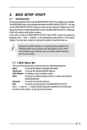
... press to enter the BIOS SETUP UTILITY after POST, restart the system by pressing + + , or by turning the system off and then back on the motherboard stores the BIOS SETUP UTILITY. 3. The BIOS FWH chip on . You may also restart by pressing the reset button on your system. You may not...
... press to enter the BIOS SETUP UTILITY after POST, restart the system by pressing + + , or by turning the system off and then back on the motherboard stores the BIOS SETUP UTILITY. 3. The BIOS FWH chip on . You may also restart by pressing the reset button on your system. You may not...
User Manual
Page 23
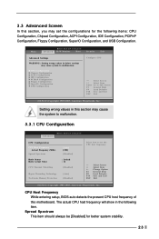
... to set the configurations for better system stability. 23 CPU Host Frequency While entering setup, BIOS auto detects the present CPU host frequency of this motherboard. Setting wrong values in the following items: CPU Configuration, Chipset Configuration, ACPI Configuration, IDE Configuration, PCIPnP Configuration, Floppy Configuration, SuperIO Configuration, and USB Configuration. The...
... to set the configurations for better system stability. 23 CPU Host Frequency While entering setup, BIOS auto detects the present CPU host frequency of this motherboard. Setting wrong values in the following items: CPU Configuration, Chipset Configuration, ACPI Configuration, IDE Configuration, PCIPnP Configuration, Floppy Configuration, SuperIO Configuration, and USB Configuration. The...
User Manual
Page 24
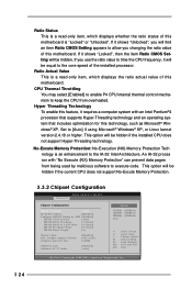
... ratio value to allow you will be hidden if the installed CPU does not support Hyper-Threading technology. Set to the core speed of this motherboard. CPU Thermal Throttling You may select [Enabled] to enable P4 CPU internal thermal control mechanism to keep the CPU from being used by SPD [Disabled..., Inc. 24 No-Excute Memory Protection: No-Execution (NX) Memory Protection Tech nology is a read -only item, which displays the ratio actual value of this motherboard is "Locked" or "Unlocked". Ratio Status This is a read -only item, which displays whether the ratio status of this...
... ratio value to allow you will be hidden if the installed CPU does not support Hyper-Threading technology. Set to the core speed of this motherboard. CPU Thermal Throttling You may select [Enabled] to enable P4 CPU internal thermal control mechanism to keep the CPU from being used by SPD [Disabled..., Inc. 24 No-Excute Memory Protection: No-Execution (NX) Memory Protection Tech nology is a read -only item, which displays the ratio actual value of this motherboard is "Locked" or "Unlocked". Ratio Status This is a read -only item, which displays whether the ratio status of this...
User Manual
Page 25
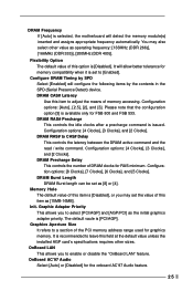
... PCI memory address range used for the onboard AC'97 Audio feature. 25 Please note that the configuration option [3] is [Disabled]. It is selected, the motherboard will detect the memory module(s) inserted and assigns appropriate frequency automatically. The default vaule is issued. Configuration options: [Auto], [2.5], [2], and [3]. DRAM RAS# Precharge This controls...
... PCI memory address range used for the onboard AC'97 Audio feature. 25 Please note that the configuration option [3] is [Disabled]. It is selected, the motherboard will detect the memory module(s) inserted and assigns appropriate frequency automatically. The default vaule is issued. Configuration options: [Auto], [2.5], [2], and [3]. DRAM RAS# Precharge This controls...
User Manual
Page 32
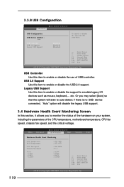
... such as mouse, keyboard,... if there is no USB device connected, "Auto" option will start to enable or disable the use of the CPU temperature, motherboard temperature, CPU fan speed, chassis fan speed, and the critical voltage. 32 Main Advanced BIOS SETUP UTILITY H/W Monitor Boot Security Exit Hardware Health Event Monitoring...
... such as mouse, keyboard,... if there is no USB device connected, "Auto" option will start to enable or disable the use of the CPU temperature, motherboard temperature, CPU fan speed, chassis fan speed, and the critical voltage. 32 Main Advanced BIOS SETUP UTILITY H/W Monitor Boot Security Exit Hardware Health Event Monitoring...
User Manual
Page 36
... install the necessary drivers to reduce the risks of CPU and motherboard damages caused by step. Since it . 4.2.4 ASRock "PC-DIY Live Demo" Program ASRock presents you a multimedia PC-DIY live demo program before you need to contact ASRock or want to know more information. 4.2 Support CD Information The... Support CD that enhance the motherboard features. 4.2.1 Running The Support CD To begin using the support CD, insert the CD into your computer....
... install the necessary drivers to reduce the risks of CPU and motherboard damages caused by step. Since it . 4.2.4 ASRock "PC-DIY Live Demo" Program ASRock presents you a multimedia PC-DIY live demo program before you need to contact ASRock or want to know more information. 4.2 Support CD Information The... Support CD that enhance the motherboard features. 4.2.1 Running The Support CD To begin using the support CD, insert the CD into your computer....

