User Manual
Page 3
... 9 1.4 Supported PCI Express VGA Card List for AGI Express Slot (PCI Express x4 10 1.5 Motherboard Layout 11 1.6 ASRock 8CH_eSATAII I/O 12 2 Installation 13 2.1 Screw Holes 13 2.2 Pre-installation Precautions 13 2.3 CPU Installation 14 2.4 Installation of Heatsink and CPU fan 16 2.5 Installation of Memory Modules (DIMM 17 2.6 Expansion Slots 19 2.7 CrossFireTM Operation Guide 20 2.8 Surround...
... 9 1.4 Supported PCI Express VGA Card List for AGI Express Slot (PCI Express x4 10 1.5 Motherboard Layout 11 1.6 ASRock 8CH_eSATAII I/O 12 2 Installation 13 2.1 Screw Holes 13 2.2 Pre-installation Precautions 13 2.3 CPU Installation 14 2.4 Installation of Heatsink and CPU fan 16 2.5 Installation of Memory Modules (DIMM 17 2.6 Expansion Slots 19 2.7 CrossFireTM Operation Guide 20 2.8 Surround...

User Manual
Page 4
3.1.1 BIOS Menu Bar 41 3.1.2 Navigation Keys 42 3.2 Main Screen 42 3.3 Advanced Screen 42 3.3.1 CPU Configuration 43 3.3.2 Chipset Configuration 45 3.3.3 ACPI Configuration 47 3.3.4 IDE Configuration 48 3.3.5 PCIPnP Configuration 50 3.3.6 Floppy Configuration 51 3.3.7 Super IO Configuration 51 3.3.8 USB Configuration 53 3.4 ... 56 4 Software Support 57 4.1 Install Operating System 57 4.2 Support CD Information 57 4.2.1 Running Support CD 57 4.2.2 Drivers Menu 57 4.2.3 Utilities Menu 57 4.2.4 "LGA 775 CPU Installation Live Demo" Program .. 57 4.2.5 Contact Information 57 4
3.1.1 BIOS Menu Bar 41 3.1.2 Navigation Keys 42 3.2 Main Screen 42 3.3 Advanced Screen 42 3.3.1 CPU Configuration 43 3.3.2 Chipset Configuration 45 3.3.3 ACPI Configuration 47 3.3.4 IDE Configuration 48 3.3.5 PCIPnP Configuration 50 3.3.6 Floppy Configuration 51 3.3.7 Super IO Configuration 51 3.3.8 USB Configuration 53 3.4 ... 56 4 Software Support 57 4.1 Install Operating System 57 4.2 Support CD Information 57 4.2.1 Running Support CD 57 4.2.2 Drivers Menu 57 4.2.3 Utilities Menu 57 4.2.4 "LGA 775 CPU Installation Live Demo" Program .. 57 4.2.5 Contact Information 57 4
User Manual
Page 5
... further notice. Chapter 3 and 4 contain the configuration guide to quality and endurance. ASRock website http://www.asrock.com 1.1 Package Contents ASRock 775XFire-eSATA2+ Motherboard (ATX Form Factor: 12.0-in x 8.6-in, 30.5 cm x 21.8 cm) ASRock 775XFire-eSATA2+ Quick Installation Guide ASRock 775XFire-eSATA2+ Support CD (including LGA 775 CPU Installation Live Demo) One 80-conductor Ultra ATA 66/100 IDE Ribbon Cable...
... further notice. Chapter 3 and 4 contain the configuration guide to quality and endurance. ASRock website http://www.asrock.com 1.1 Package Contents ASRock 775XFire-eSATA2+ Motherboard (ATX Form Factor: 12.0-in x 8.6-in, 30.5 cm x 21.8 cm) ASRock 775XFire-eSATA2+ Quick Installation Guide ASRock 775XFire-eSATA2+ Support CD (including LGA 775 CPU Installation Live Demo) One 80-conductor Ultra ATA 66/100 IDE Ribbon Cable...

User Manual
Page 6
...D, supporting Conroe, Presler and Cedar Mill processors (in , 30.5 cm x 21.8 cm - Supports Untied Overclocking Technology (see CAUTION 6) - ASRock U-COP (see CAUTION 2) - Realtek ALC888 7.1 channel CODEC with High Definition Audio - Dual Channel DDRII Memory Technology (see CAUTION 4) - capacity... 1 x PCI Express x16 slot - 1 x AGI Express slot (PCI Express x4) (see CAUTION 5) - Supports EM64T CPU - Supports Wake-On-LAN ASRock 8CH_eSATAII I /O - CPU Frequency Stepless Control (see CAUTION 7) - 1 x PCI Express x1 slot - Supports Hyper-Threading Technology (see CAUTION 8) 6...
...D, supporting Conroe, Presler and Cedar Mill processors (in , 30.5 cm x 21.8 cm - Supports Untied Overclocking Technology (see CAUTION 6) - ASRock U-COP (see CAUTION 2) - Realtek ALC888 7.1 channel CODEC with High Definition Audio - Dual Channel DDRII Memory Technology (see CAUTION 4) - capacity... 1 x PCI Express x16 slot - 1 x AGI Express slot (PCI Express x4) (see CAUTION 5) - Supports EM64T CPU - Supports Wake-On-LAN ASRock 8CH_eSATAII I /O - CPU Frequency Stepless Control (see CAUTION 7) - 1 x PCI Express x1 slot - Supports Hyper-Threading Technology (see CAUTION 8) 6...
User Manual
Page 7
...connectors), support "Hot Plug" function (see CAUTION 12) - AMI Legal BIOS - Drivers, Utilities, AntiVirus Software (Trial Version) - CPU Quiet Fan - FCC, CE, WHQL 7 Chassis Temperature Sensing - SMBIOS 2.3.1 Support - CD in header - Microsoft® Windows&#...1 x HDMI_SPDIF header - Voltage Monitoring: +12V, +5V, +3.3V, Vcore - Chassis Fan Tachometer - CPU/Chassis FAN connector - 20 pin ATX power connector - 4 pin 12V power connector - Supports "Plug and Play" - CPU Temperature Sensing - Front panel audio connector - 3 x USB 2.0 headers (support 6 USB 2.0 ports)...
...connectors), support "Hot Plug" function (see CAUTION 12) - AMI Legal BIOS - Drivers, Utilities, AntiVirus Software (Trial Version) - CPU Quiet Fan - FCC, CE, WHQL 7 Chassis Temperature Sensing - SMBIOS 2.3.1 Support - CD in header - Microsoft® Windows&#...1 x HDMI_SPDIF header - Voltage Monitoring: +12V, +5V, +3.3V, Vcore - Chassis Fan Tachometer - CPU/Chassis FAN connector - 20 pin ATX power connector - 4 pin 12V power connector - Supports "Plug and Play" - CPU Temperature Sensing - Front panel audio connector - 3 x USB 2.0 headers (support 6 USB 2.0 ports)...

User Manual
Page 8
...CPU overheat is not ready yet. For audio output, this motherboard supports both stereo and mono modes. Before installing SATAII hard disk to SATAII connector, please read "Un- You can also connect SATA hard disk to our website in the future. Power Management for details. 3. ASRock website http://www.asrock..." on page 31 for AGI Express Slot (PCI Express x4)" on page 17 for proper installation. 4. Frequencies other than the recommended CPU bus frequencies may cause the instability of PCI Express VGA card, please refer to SATAII mode. Before you install the PC system. 7....
...CPU overheat is not ready yet. For audio output, this motherboard supports both stereo and mono modes. Before installing SATAII hard disk to SATAII connector, please read "Un- You can also connect SATA hard disk to our website in the future. Power Management for details. 3. ASRock website http://www.asrock..." on page 31 for AGI Express Slot (PCI Express x4)" on page 17 for proper installation. 4. Frequencies other than the recommended CPU bus frequencies may cause the instability of PCI Express VGA card, please refer to SATAII mode. Before you install the PC system. 7....
User Manual
Page 9
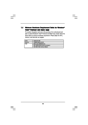
Please adopt the CPU, memory, and VGA that we suggest. CPU Memory VGA Celeron D 326 512MB Single Channel DX9.0 with WDDM Driver with 128bit VGA memory (Premium) with 64bit VGA memory (Basic) 9 1.3 Minimum Hardware Requirement Table for Windows® VistaTM Premium and Basic Logo For system integrators and users who purchase this motherboard and plan to submit Windows® VistaTM Premium and Basic logo, please follow the below table for minimum hardware requirement.
Please adopt the CPU, memory, and VGA that we suggest. CPU Memory VGA Celeron D 326 512MB Single Channel DX9.0 with WDDM Driver with 128bit VGA memory (Premium) with 64bit VGA memory (Basic) 9 1.3 Minimum Hardware Requirement Table for Windows® VistaTM Premium and Basic Logo For system integrators and users who purchase this motherboard and plan to submit Windows® VistaTM Premium and Basic logo, please follow the below table for minimum hardware requirement.

User Manual
Page 14
... 1-3. Step 2. Pin1 orientation key notch orientation key notch Pin1 alignment key alignment key 775-LAND CPU 775-Pin Socket 14 black line black line Open the socket: Step 1-1. Hold the CPU by depressing down and out on the socket. Do not force to fully open position at approximately... at approximately 135 degrees. Step 1. Insert the 775-LAND CPU: Step 2-1. 2.3 CPU Installation For the installation of Intel 775-LAND CPU, please follow the steps below. 775-Pin Socket Overview Before you insert the 775-LAND CPU into the socket if above situation is any bent pin on...
... 1-3. Step 2. Pin1 orientation key notch orientation key notch Pin1 alignment key alignment key 775-LAND CPU 775-Pin Socket 14 black line black line Open the socket: Step 1-1. Hold the CPU by depressing down and out on the socket. Do not force to fully open position at approximately... at approximately 135 degrees. Step 1. Insert the 775-LAND CPU: Step 2-1. 2.3 CPU Installation For the installation of Intel 775-LAND CPU, please follow the steps below. 775-Pin Socket Overview Before you insert the 775-LAND CPU into the socket if above situation is any bent pin on...

User Manual
Page 15
Carefully place the CPU into the socket by using a purely vertical motion. Step 3. Close the socket: Step 4-1. For proper inserting, please ensure to handle and avoid kicking off the ... be placed if returning the motherboard for after service. Secure load lever with the two alignment keys of load lever. 15 Step 2-4. Verify that the CPU is recommended to use the cap tab to match the two orientation key notches of the...
Carefully place the CPU into the socket by using a purely vertical motion. Step 3. Close the socket: Step 4-1. For proper inserting, please ensure to handle and avoid kicking off the ... be placed if returning the motherboard for after service. Secure load lever with the two alignment keys of load lever. 15 Step 2-4. Verify that the CPU is recommended to use the cap tab to match the two orientation key notches of the...

User Manual
Page 16
...with remaining fasteners. Step 5. Step 6. Before you installed the heatsink, you press down on fastener caps with Intel 775-LAND CPU to dissipate heat. For proper installation, please kindly refer to the instruction manuals of heatsink and cooling fan compliant with thumb to ...improve heat dissipation. Step 4. Step 2. Repeat with the motherboard throughholes. Please adopt the type of your CPU fan and heatsink. Place the heatsink onto the socket. Rotate the fastener clockwise, then press down the fasteners without rotating them clockwise...
...with remaining fasteners. Step 5. Step 6. Before you installed the heatsink, you press down on fastener caps with Intel 775-LAND CPU to dissipate heat. For proper installation, please kindly refer to the instruction manuals of heatsink and cooling fan compliant with thumb to ...improve heat dissipation. Step 4. Step 2. Repeat with the motherboard throughholes. Please adopt the type of your CPU fan and heatsink. Place the heatsink onto the socket. Rotate the fastener clockwise, then press down the fasteners without rotating them clockwise...
User Manual
Page 27
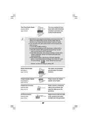
... of audio devices. 1. Please follow the instruction in our manual and chassis manual to the ground pin. 27 CPU Fan Connector (4-pin CPU_FAN1) (see p.11 No. 6) +12V CPU_FAN_SPEED GND FAN_SPEED_CONTROL Please connect a CPU fan cable to this connector and match the black wire to install your system. 2. Set the Front Panel Control...
... of audio devices. 1. Please follow the instruction in our manual and chassis manual to the ground pin. 27 CPU Fan Connector (4-pin CPU_FAN1) (see p.11 No. 6) +12V CPU_FAN_SPEED GND FAN_SPEED_CONTROL Please connect a CPU fan cable to this connector and match the black wire to install your system. 2. Set the Front Panel Control...
User Manual
Page 40
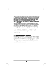
After reading the floppy disk, the driver will show you the actual CPU host frequency in the fixed mode so that FSB can start to fixed PCI bus....Windows XP64)" for details. (If you select AHCI mode and plan to install Windows® VistaTM on your system. Therefore, CPU FSB is in the following item. At the beginning of BIOS setup to make a SATA driver diskette. STEP 3: Install Windows&#... to install according to install a third-party SCSI or RAID driver. If you set "CPU Host Frequency" option of Windows® setup, press F6 to the mode you choose and the OS you install.
After reading the floppy disk, the driver will show you the actual CPU host frequency in the fixed mode so that FSB can start to fixed PCI bus....Windows XP64)" for details. (If you select AHCI mode and plan to install Windows® VistaTM on your system. Therefore, CPU FSB is in the following item. At the beginning of BIOS setup to make a SATA driver diskette. STEP 3: Install Windows&#... to install according to install a third-party SCSI or RAID driver. If you set "CPU Host Frequency" option of Windows® setup, press F6 to the mode you choose and the OS you install.

User Manual
Page 42
...date. 3.3 Advanced Screen In this item to specify the system time. 3.1.2 Navigation Keys Please check the following items: CPU Configuration, Chipset Configuration, ACPI Configuration, IDE Configuration, PCIPnP Configuration, Floppy Configuration, SuperIO Configuration, and USB Configuration. 42 System...Boot Security Exit System Overview System Time System Date [14:00:09] [Fri 04/21/2006] BIOS Version : 775XFire-eSATA2+ BIOS P1.00 Processor Type : Intel (R) CPU 3.40 GHz (64bit supported) Processor Speed : 3400 MHz Microcode Update : F34/17 Cache Size : 1024KB Total ...
...date. 3.3 Advanced Screen In this item to specify the system time. 3.1.2 Navigation Keys Please check the following items: CPU Configuration, Chipset Configuration, ACPI Configuration, IDE Configuration, PCIPnP Configuration, Floppy Configuration, SuperIO Configuration, and USB Configuration. 42 System...Boot Security Exit System Overview System Time System Date [14:00:09] [Fri 04/21/2006] BIOS Version : 775XFire-eSATA2+ BIOS P1.00 Processor Type : Intel (R) CPU 3.40 GHz (64bit supported) Processor Speed : 3400 MHz Microcode Update : F34/17 Cache Size : 1024KB Total ...

User Manual
Page 43
... Load Defaults Save and Exit Exit v02.54 (C) Copyright 1985-2005, American Megatrends, Inc. Setting wrong values in this motherboard. CPU Thermal Throttling No-Excute Memory Protection Hyper Threading Technology Intel (R) SpeedStep(tm) tech. [Disabled] [Disabled] [Enabled] [Enabled]...Boot Security Exit Advanced Settings WARNING : Setting wrong values in below sections may cause the system to malfunction. 3.3.1 CPU Configuration BIOS SETUP UTILITY Advanced CPU Configuration CPU Host Frequency Actual Frequency (MHz) Boot Failure Guard Spread Spectrum [Auto] [200] [Enabled] [Auto] Ratio...
... Load Defaults Save and Exit Exit v02.54 (C) Copyright 1985-2005, American Megatrends, Inc. Setting wrong values in this motherboard. CPU Thermal Throttling No-Excute Memory Protection Hyper Threading Technology Intel (R) SpeedStep(tm) tech. [Disabled] [Disabled] [Enabled] [Enabled]...Boot Security Exit Advanced Settings WARNING : Setting wrong values in below sections may cause the system to malfunction. 3.3.1 CPU Configuration BIOS SETUP UTILITY Advanced CPU Configuration CPU Host Frequency Actual Frequency (MHz) Boot Failure Guard Spread Spectrum [Auto] [200] [Enabled] [Auto] Ratio...

User Manual
Page 44
... MWAIT and requires no hardware support from the chipset. Ratio CMOS Setting If the ratio status is unlocked, you will be hidden if the installed CPU does not support Hyper-Threading technology. This option will be enabled in order to execute code. Intel (R) SpeedStep(tm) tech. If you select [Auto... (NX) Memory Protection Technology is set the "Power Schemes" as Microsoft® Windows® XP. This option will be hidden if the installed CPU does not support Intel (R) Virtualization Technology. Set to the IA-32 Intel Architecture. This should be hidden if the current...
... MWAIT and requires no hardware support from the chipset. Ratio CMOS Setting If the ratio status is unlocked, you will be hidden if the installed CPU does not support Hyper-Threading technology. This option will be enabled in order to execute code. Intel (R) SpeedStep(tm) tech. If you select [Auto... (NX) Memory Protection Technology is set the "Power Schemes" as Microsoft® Windows® XP. This option will be hidden if the installed CPU does not support Intel (R) Virtualization Technology. Set to the IA-32 Intel Architecture. This should be hidden if the current...

User Manual
Page 53
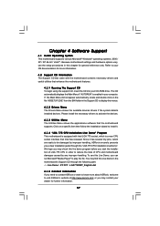
...Copyright 1985-2005, American Megatrends, Inc. etc. BIOS SETUP UTILITY Main Advanced H/W Monitor Boot Security Exit Hardware Health Event Monitoring CPU Temperature M / B Temperature : 37 C / 98 F : 31 C / 87 F Target Fan Speed Fast Middle Slow CPU Fan Speed Chassis Fan Speed : 3400 RPM : N/A Vcore + 3.30V + 5.00V + 12.00V : 1.629V :... 3.306V : 5.067V : 11.890V CPU Quiet Fan Target CPU Temperature ( C) Tolerance ( C) Target Fan Speed [Enabled] [50] [02] [Fast] F1 F9 F10 ESC Select Screen Select Item General...
...Copyright 1985-2005, American Megatrends, Inc. etc. BIOS SETUP UTILITY Main Advanced H/W Monitor Boot Security Exit Hardware Health Event Monitoring CPU Temperature M / B Temperature : 37 C / 98 F : 31 C / 87 F Target Fan Speed Fast Middle Slow CPU Fan Speed Chassis Fan Speed : 3400 RPM : N/A Vcore + 3.30V + 5.00V + 12.00V : 1.629V :... 3.306V : 5.067V : 11.890V CPU Quiet Fan Target CPU Temperature ( C) Tolerance ( C) Target Fan Speed [Enabled] [50] [02] [Fast] F1 F9 F10 ESC Select Screen Select Item General...

User Manual
Page 54
...-2005, American Megatrends, Inc. 54 HDS722580VL] [CD / DVD: 3S - Target Fan Speed Use this option as [Disabled], the CPU fan will operate in full speed. Main Advanced BIOS SETUP UTILITY H/W Monitor Boot Security Exit Boot Settings Boot Settings Configuration Configure Settings during... Speed" appear to configure the boot settings and the boot priority. The default value is [2], which means the error of CPU fan. If you adjusting them. Target CPU Temperature ( C) The target temperature will be between 45 C and 65 C. Tolerance ( C) The default value of tolerance is...
...-2005, American Megatrends, Inc. 54 HDS722580VL] [CD / DVD: 3S - Target Fan Speed Use this option as [Disabled], the CPU fan will operate in full speed. Main Advanced BIOS SETUP UTILITY H/W Monitor Boot Security Exit Boot Settings Boot Settings Configuration Configure Settings during... Speed" appear to configure the boot settings and the boot priority. The default value is [2], which means the error of CPU fan. If you adjusting them. Target CPU Temperature ( C) The target temperature will be between 45 C and 65 C. Tolerance ( C) The default value of tolerance is...
User Manual
Page 57
... in the motherboard's Support CD through this Live Demo, you can run Microsoft® Media Player® to reduce the risks of CPU and motherboard damages caused by improper handling, ASRock sincerely presents you a clear installation guide through the following path: ..\ Live Demo \ PC DIY \ LGA775INST_English.dat 4.2.5 Contact Information If you start...
... in the motherboard's Support CD through this Live Demo, you can run Microsoft® Media Player® to reduce the risks of CPU and motherboard damages caused by improper handling, ASRock sincerely presents you a clear installation guide through the following path: ..\ Live Demo \ PC DIY \ LGA775INST_English.dat 4.2.5 Contact Information If you start...
Quick Installation Guide
Page 2
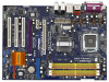
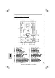
...eSATAII Connector (eSATAII_BOTTOM) 16 Serial ATAII Connector (SATAII_BLUE (PORT0)) 35 eSATAII Connector (eSATAII_TOP) 17 Chassis Fan Connector (CHA_FAN1) 2 ASRock 775XFire-eSATA2+ Motherboard Motherboard Layout English 1 PS2_USB_PWR1 Jumper 18 System Panel Header (PANEL1) 2 ATX 12V Connector (ATX12V1) 19 Chassis Speaker Header ...1) 3 SLI / XFIRE Power Connector 20 USB 2.0 Header (USB67, Blue) 4 775-Pin CPU Socket 21 South Bridge Controller 5 North Bridge Controller 22 USB 2.0 Header (USB45, Blue) 6 CPU Fan Connector (CPU_FAN1) 23 USB 2.0 Header (USB23, Blue) 7 2 x 240-pin DDRII...
...eSATAII Connector (eSATAII_BOTTOM) 16 Serial ATAII Connector (SATAII_BLUE (PORT0)) 35 eSATAII Connector (eSATAII_TOP) 17 Chassis Fan Connector (CHA_FAN1) 2 ASRock 775XFire-eSATA2+ Motherboard Motherboard Layout English 1 PS2_USB_PWR1 Jumper 18 System Panel Header (PANEL1) 2 ATX 12V Connector (ATX12V1) 19 Chassis Speaker Header ...1) 3 SLI / XFIRE Power Connector 20 USB 2.0 Header (USB67, Blue) 4 775-Pin CPU Socket 21 South Bridge Controller 5 North Bridge Controller 22 USB 2.0 Header (USB45, Blue) 6 CPU Fan Connector (CPU_FAN1) 23 USB 2.0 Header (USB23, Blue) 7 2 x 240-pin DDRII...
Quick Installation Guide
Page 4
... Installation Guide contains introduction of this manual occur, the updated version will be found in the user manual presented in , 30.5 cm x 21.8 cm) ASRock 775XFire-eSATA2+ Quick Installation Guide ASRock 775XFire-eSATA2+ Support CD (including LGA 775 CPU Installation Live Demo) One 80-conductor Ultra ATA 66/100 IDE Ribbon Cable One Ribbon Cable for purchasing...
... Installation Guide contains introduction of this manual occur, the updated version will be found in the user manual presented in , 30.5 cm x 21.8 cm) ASRock 775XFire-eSATA2+ Quick Installation Guide ASRock 775XFire-eSATA2+ Support CD (including LGA 775 CPU Installation Live Demo) One 80-conductor Ultra ATA 66/100 IDE Ribbon Cable One Ribbon Cable for purchasing...


