User Manual
Page 8
.... ASRock website http://www.asrock.com 8 Although this motherboard supports 2-channel, 4-channel, 6-channel, and 8-channel modes. Frequencies other than the recommended CPU bus frequencies may cause the instability of "Hyper Threading Technology", please check page 33. 2. For microphone input, this motherboard supports both stereo and mono modes. Before you resume the system, please check if the CPU fan on page 29 for USB 2.0 works fine under Microsoft® Windows® VistaTM 64-bit...
.... ASRock website http://www.asrock.com 8 Although this motherboard supports 2-channel, 4-channel, 6-channel, and 8-channel modes. Frequencies other than the recommended CPU bus frequencies may cause the instability of "Hyper Threading Technology", please check page 33. 2. For microphone input, this motherboard supports both stereo and mono modes. Before you resume the system, please check if the CPU fan on page 29 for USB 2.0 works fine under Microsoft® Windows® VistaTM 64-bit...

User Manual
Page 10
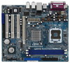
... PCI1 4CoreDX90-VSTA PCI2 USB2.0 PCI3 HDMR1 USB4_5 1 USB6_7 1 VIA VT8237A FLOPPY1 CMOS Battery CLRCMOS1 SPEAKER1 1 PANEL 1 PLED PWRBTN 1 HDLED RESET SATA1 SATA2 SATA 10 11 12 13 20 19 18 17 1615 14 1 PS2_USB_PWR1 Jumper 15 South Bridge Controller 2 ATX 12V Connector (ATX12V1) 16 Chassis Speaker Header (SPEAKER 1) 3 ATX Power Connector (ATXPWR1) 17 Clear CMOS Jumper (CLRCMOS1) 4 Chassis Fan Connector (CHA_FAN1) 18 Floppy Connector (FLOPPY1) 5 North Bridge Controller 19 HDMR Slot (HDMR1) 6 775-Pin CPU Socket 20 Front Panel Audio Header (HD_AUDIO1) 7 2 x 184-pin...
... PCI1 4CoreDX90-VSTA PCI2 USB2.0 PCI3 HDMR1 USB4_5 1 USB6_7 1 VIA VT8237A FLOPPY1 CMOS Battery CLRCMOS1 SPEAKER1 1 PANEL 1 PLED PWRBTN 1 HDLED RESET SATA1 SATA2 SATA 10 11 12 13 20 19 18 17 1615 14 1 PS2_USB_PWR1 Jumper 15 South Bridge Controller 2 ATX 12V Connector (ATX12V1) 16 Chassis Speaker Header (SPEAKER 1) 3 ATX Power Connector (ATXPWR1) 17 Clear CMOS Jumper (CLRCMOS1) 4 Chassis Fan Connector (CHA_FAN1) 18 Floppy Connector (FLOPPY1) 5 North Bridge Controller 19 HDMR Slot (HDMR1) 6 775-Pin CPU Socket 20 Front Panel Audio Header (HD_AUDIO1) 7 2 x 184-pin...

User Manual
Page 20
... motherboard. Please follow the instruction in our manual and chassis manual to the power connector on the drive. Each USB 2.0 header can support two USB 2.0 ports. Infrared Module Header (5-pin IR1) (see p.10, No. 26) Internal Audio Connector (4-pin CD1) (CD1: see p.10, No. 20) GND PRESENCE# MIC_RET OUT_RET 1 OUT2_L J_SENSE OUT2_R MIC2_R MIC2_L This is an interface for the front panel audio cable that allows convenient connection and control of audio devices. 1. Serial ATA (SATA) Power Cable (Optional) connect to the SATA HDD power connector connect...
... motherboard. Please follow the instruction in our manual and chassis manual to the power connector on the drive. Each USB 2.0 header can support two USB 2.0 ports. Infrared Module Header (5-pin IR1) (see p.10, No. 26) Internal Audio Connector (4-pin CD1) (CD1: see p.10, No. 20) GND PRESENCE# MIC_RET OUT_RET 1 OUT2_L J_SENSE OUT2_R MIC2_R MIC2_L This is an interface for the front panel audio cable that allows convenient connection and control of audio devices. 1. Serial ATA (SATA) Power Cable (Optional) connect to the SATA HDD power connector connect...

User Manual
Page 24
... instructions step by the chipset because of its limitation, the SATA Hot Plug support information of SATA HDD Hot Plug feature carefully. SATA power cable with SATA 15-pin power connector interface A. Even some SATA HDDs provide both SATA 15-pin power connector and IDE 1x4-pin conventional power connector interfaces, the IDE 1x4-pin conventional power connector interface is indicated in the product spec on our support website: www.asrock.com 4. 2.11 SATA HDD Hot Plug Feature and Operation Guide This motherboard supports Hot Plug feature for our motherboard...
... instructions step by the chipset because of its limitation, the SATA Hot Plug support information of SATA HDD Hot Plug feature carefully. SATA power cable with SATA 15-pin power connector interface A. Even some SATA HDDs provide both SATA 15-pin power connector and IDE 1x4-pin conventional power connector interfaces, the IDE 1x4-pin conventional power connector interface is indicated in the product spec on our support website: www.asrock.com 4. 2.11 SATA HDD Hot Plug Feature and Operation Guide This motherboard supports Hot Plug feature for our motherboard...
User Manual
Page 28
... install SATA drivers from the Support CD again so that , please insert Windows® VistaTM / Windows® VistaTM 64-bit optical disk into the optical drive again to load the VIA® RAID drivers. Enter BIOS SETUP UTILITY Advanced screen IDE Configuration. At the beginning of the document in the following path in the Support CD: .. \ RAID Installation Guide STEP 3: Install Windows® VistaTM / Windows® VistaTM 64-bit OS on your optical drive, and click the "Load Driver" button on...
... install SATA drivers from the Support CD again so that , please insert Windows® VistaTM / Windows® VistaTM 64-bit optical disk into the optical drive again to load the VIA® RAID drivers. Enter BIOS SETUP UTILITY Advanced screen IDE Configuration. At the beginning of the document in the following path in the Support CD: .. \ RAID Installation Guide STEP 3: Install Windows® VistaTM / Windows® VistaTM 64-bit OS on your optical drive, and click the "Load Driver" button on...
User Manual
Page 29
... your SATA HDDs without RAID functions, please follow below steps. Enter BIOS SETUP UTILITY Advanced screen IDE Configuration. B. Please refer to [Auto], which means during overclocking, but PCI / PCIE bus is untied during overclocking, FSB enjoys better margin due to install Windows® 2000, Windows® XP, Windows® XP 64-bit, Windows® VistaTM or Windows® VistaTM 64-bit OS on SATA HDDs,please set "CPU Host Frequency" option of the document in Windows® environment, please install SATA drivers from the Support...
... your SATA HDDs without RAID functions, please follow below steps. Enter BIOS SETUP UTILITY Advanced screen IDE Configuration. B. Please refer to [Auto], which means during overclocking, but PCI / PCIE bus is untied during overclocking, FSB enjoys better margin due to install Windows® 2000, Windows® XP, Windows® XP 64-bit, Windows® VistaTM or Windows® VistaTM 64-bit OS on SATA HDDs,please set "CPU Host Frequency" option of the document in Windows® environment, please install SATA drivers from the Support...

User Manual
Page 32
...Sub Screen F1 General Help F9 Load Defaults F10 Save and Exit ESC Exit v02.54 (C) Copyright 1985-2003, American Megatrends, Inc. mode]. mode] and [Async. CPU Configuration Chipset Configuration ACPI Configuration IDE Configuration PCIPnP Configuration Floppy Configuration SuperIO Configuration USB Configuration Configure CPU Select Screen Select Item Enter Go to malfunction. 3.3.1 CPU Configuration BIOS SETUP UTILITY Advanced CPU Configuration CPU Host Frequency Actual Frequency (MHz) Boot Failure Guard Spread Spectrum PCIE clock operation mode [Auto] [200] [Enabled] [Disabled] [Sync...
...Sub Screen F1 General Help F9 Load Defaults F10 Save and Exit ESC Exit v02.54 (C) Copyright 1985-2003, American Megatrends, Inc. mode]. mode] and [Async. CPU Configuration Chipset Configuration ACPI Configuration IDE Configuration PCIPnP Configuration Floppy Configuration SuperIO Configuration USB Configuration Configure CPU Select Screen Select Item Enter Go to malfunction. 3.3.1 CPU Configuration BIOS SETUP UTILITY Advanced CPU Configuration CPU Host Frequency Actual Frequency (MHz) Boot Failure Guard Spread Spectrum PCIE clock operation mode [Auto] [200] [Enabled] [Disabled] [Sync...

User Manual
Page 33
... with "No Execute (NX) Memory Protection" can utilize the additional hardware capabilities provided by malicious software to execute code. This should be hidden if the current CPU does not support CPU Thermal Throttling. In the C1 power state, the processor maintains the context of the system caches. CPU Thermal Throttling You may select [Enabled] to enable P4 CPU internal thermal control mechanism to allow you...
... with "No Execute (NX) Memory Protection" can utilize the additional hardware capabilities provided by malicious software to execute code. This should be hidden if the current CPU does not support CPU Thermal Throttling. In the C1 power state, the processor maintains the context of the system caches. CPU Thermal Throttling You may select [Enabled] to enable P4 CPU internal thermal control mechanism to allow you...

User Manual
Page 37
... use the PCI BUS while the transaction is plugged. PCI Delay Transaction Enable PCI Delay Transaction to allow other PCI masters to use this motherboard to enable or disable CD-In of this option. configuration options: [Normal], [Fast]. Configuration options: [Low], [Normal], [High] and [Ultra High]. CD-In Use this feature when using PCI cards that are not PCI 2.1 compliant. IDE Drive Strength This allows you to set the North Bridge and South Bridge V-Link Speed of the onboard IDE controller. OnBoard LAN...
... use the PCI BUS while the transaction is plugged. PCI Delay Transaction Enable PCI Delay Transaction to allow other PCI masters to use this motherboard to enable or disable CD-In of this option. configuration options: [Normal], [Fast]. Configuration options: [Low], [Normal], [High] and [Ultra High]. CD-In Use this feature when using PCI cards that are not PCI 2.1 compliant. IDE Drive Strength This allows you to set the North Bridge and South Bridge V-Link Speed of the onboard IDE controller. OnBoard LAN...

User Manual
Page 39
... this item to the configurations of device connected to enable or disable the onboard IDE controller. IDE Device Configuration You may set the IDE configuration for the device that you want to operate RAID function on SATA HDDs, please select [RAID]. 3.3.4 IDE Configuration BIOS SETUP UTILITY Advanced IDE Configuration OnBoard IDE Controller SATA Operation Mode [Enabled] [non-RAID] To enable or disable the onboard IDE controller. OnBoard IDE Controller Use this item to the system. +F1 F9 F10 ESC Select Screen Select Item Change Option General Help Load Defaults Save and Exit Exit...
... this item to the configurations of device connected to enable or disable the onboard IDE controller. IDE Device Configuration You may set the IDE configuration for the device that you want to operate RAID function on SATA HDDs, please select [RAID]. 3.3.4 IDE Configuration BIOS SETUP UTILITY Advanced IDE Configuration OnBoard IDE Controller SATA Operation Mode [Enabled] [non-RAID] To enable or disable the onboard IDE controller. OnBoard IDE Controller Use this item to the system. +F1 F9 F10 ESC Select Screen Select Item Change Option General Help Load Defaults Save and Exit Exit...

User Manual
Page 40
... hard disk. Configuration options: [Not Installed], [Auto], [CD/DVD], and [ARMD]. [Not Installed]: Select [Not Installed] to disable the use a disk utility, such as MO. TYPE Use this item to configure the type of the IDE device that you specify. DMA Mode DMA capability allows the improved transfer-speed and data-integrity for Netware and UNIX user, select [Disabled] to automatically detect the hard disk drive. for compatible IDE devices. S.M.A.R.T. Make sure to set the PIO mode to enable or disable the S.M.A.R.T. (Self-Monitoring...
... hard disk. Configuration options: [Not Installed], [Auto], [CD/DVD], and [ARMD]. [Not Installed]: Select [Not Installed] to disable the use a disk utility, such as MO. TYPE Use this item to configure the type of the IDE device that you specify. DMA Mode DMA capability allows the improved transfer-speed and data-integrity for Netware and UNIX user, select [Disabled] to automatically detect the hard disk drive. for compatible IDE devices. S.M.A.R.T. Make sure to set the PIO mode to enable or disable the S.M.A.R.T. (Self-Monitoring...

User Manual
Page 46
... Screen Select Item Enter Change F1 General Help F9 Load Defaults F10 Save and Exit ESC Exit v02.54 (C) Copyright 1985-2003, American Megatrends, Inc. 46 VIA SATA Raid Utility Use this item to [On], it . BIOS SETUP UTILITY Main Advanced H/W Monitor Boot Security Exit Security Settings Supervisor Password : Not Installed User Password : Not Installed Change Supervisor Password Change User Password Clear User Password Install or Change the password. Boot Up Num-Lock If this section, you may set to enable or disable the Boot From Onboard LAN feature...
... Screen Select Item Enter Change F1 General Help F9 Load Defaults F10 Save and Exit ESC Exit v02.54 (C) Copyright 1985-2003, American Megatrends, Inc. 46 VIA SATA Raid Utility Use this item to [On], it . BIOS SETUP UTILITY Main Advanced H/W Monitor Boot Security Exit Security Settings Supervisor Password : Not Installed User Password : Not Installed Change Supervisor Password Change User Password Clear User Password Install or Change the password. Boot Up Num-Lock If this section, you may set to enable or disable the Boot From Onboard LAN feature...
User Manual
Page 48
...-bit. Because motherboard settings and hardware options vary, use the setup procedures in this chapter for more about ASRock, welcome to know more information. 4.2 Support CD Information The Support CD that came with the motherboard contains necessary drivers and useful utilities that the motherboard supports. The CD automatically displays the Main Menu if "AUTORUN" is enabled in the Support CD to activate the devices. 4.2.3 Utilities Menu The Utilities Menu shows the applications software that enhance the motherboard...
...-bit. Because motherboard settings and hardware options vary, use the setup procedures in this chapter for more about ASRock, welcome to know more information. 4.2 Support CD Information The Support CD that came with the motherboard contains necessary drivers and useful utilities that the motherboard supports. The CD automatically displays the Main Menu if "AUTORUN" is enabled in the Support CD to activate the devices. 4.2.3 Utilities Menu The Utilities Menu shows the applications software that enhance the motherboard...
Quick Installation Guide
Page 7
.... As long as we have the latest driver, we will automatically shutdown. Please read "Untied Overclocking Technology" on the motherboard functions properly and unplug the power cord, then plug it to perform over-clocking. For audio output, this motherboard supports 2-channel, 4-channel, 6-channel, and 8-channel modes. Power Management for Microsoft® Windows® VistaTM / VistaTM 64-bit driver and related information. Frequencies other than the recommended CPU bus frequencies may cause the instability of "User Manual...
.... As long as we have the latest driver, we will automatically shutdown. Please read "Untied Overclocking Technology" on the motherboard functions properly and unplug the power cord, then plug it to perform over-clocking. For audio output, this motherboard supports 2-channel, 4-channel, 6-channel, and 8-channel modes. Power Management for Microsoft® Windows® VistaTM / VistaTM 64-bit driver and related information. Frequencies other than the recommended CPU bus frequencies may cause the instability of "User Manual...
Quick Installation Guide
Page 16
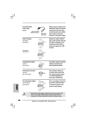
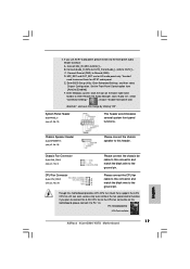
...chassis manual to the power connector of the power supply. Each USB 2.0 header can support two USB 2.0 ports. Infrared Module Header (5-pin IR1) (see p.2, No. 26) Internal Audio Connector (4-pin CD1) (CD1: see p.2, No. 22) Front Panel Audio Header (9-pin HD_AUDIO1) (see p.2 No. 10) Besides four default USB 2.0 ports on the I/O panel, there are two USB 2.0 headers on the drive. Then connect the white end of SATA power cable to install your system. 16 ASRock 4CoreDX90-VSTA Motherboard English Serial ATA (SATA) Power Cable (Optional) connect to the SATA HDD power connector connect...
...chassis manual to the power connector of the power supply. Each USB 2.0 header can support two USB 2.0 ports. Infrared Module Header (5-pin IR1) (see p.2, No. 26) Internal Audio Connector (4-pin CD1) (CD1: see p.2, No. 22) Front Panel Audio Header (9-pin HD_AUDIO1) (see p.2 No. 10) Besides four default USB 2.0 ports on the I/O panel, there are two USB 2.0 headers on the drive. Then connect the white end of SATA power cable to install your system. 16 ASRock 4CoreDX90-VSTA Motherboard English Serial ATA (SATA) Power Cable (Optional) connect to the SATA HDD power connector connect...
Quick Installation Guide
Page 17
.... Enter Windows system. Pin 1-3 Connected 3-Pin Fan Installation 17 ASRock 4CoreDX90-VSTA Motherboard English 2. Connect Mic_IN (MIC) to connect them for HD audio panel only. D. Click the icon on this motherboard, please connect it to [Enabled]. B. MIC_RET and OUT_RET are for AC'97 audio panel. Click "Audio I/O", select "Connector Settings" , choose "Disable front panel jack detection", and save the change by clicking "OK". Chassis Speaker Header (4-pin SPEAKER 1) (see p.2, No. 4) Please connect the chassis fan cable to this motherboard provides 4-Pin CPU fan...
.... Enter Windows system. Pin 1-3 Connected 3-Pin Fan Installation 17 ASRock 4CoreDX90-VSTA Motherboard English 2. Connect Mic_IN (MIC) to connect them for HD audio panel only. D. Click the icon on this motherboard, please connect it to [Enabled]. B. MIC_RET and OUT_RET are for AC'97 audio panel. Click "Audio I/O", select "Connector Settings" , choose "Disable front panel jack detection", and save the change by clicking "OK". Chassis Speaker Header (4-pin SPEAKER 1) (see p.2, No. 4) Please connect the chassis fan cable to this motherboard provides 4-Pin CPU fan...
Quick Installation Guide
Page 19
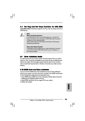
... ASRock 4CoreDX90-VSTA Motherboard English Install HDMR card driver from up to bottom side to install those required drivers. 2.8 Hot Plug and Hot Swap Functions for SATA HDDs 4CoreDX90-VSTA motherboard supports Hot Plug and Hot Swap functions for the action to insert and remove the SATA HDDs while the system is still power-on and in working condition. Reboot your system. 3. If SATA HDDs are NOT set for RAID configuration, it is called "Hot Swap" for SATA Devices...
... ASRock 4CoreDX90-VSTA Motherboard English Install HDMR card driver from up to bottom side to install those required drivers. 2.8 Hot Plug and Hot Swap Functions for SATA HDDs 4CoreDX90-VSTA motherboard supports Hot Plug and Hot Swap functions for the action to insert and remove the SATA HDDs while the system is still power-on and in working condition. Reboot your system. 3. If SATA HDDs are NOT set for RAID configuration, it is called "Hot Swap" for SATA Devices...
Quick Installation Guide
Page 21
... SATA HDDs with RAID functions, please follow the instruction to load the VIA® RAID drivers. If you need to check the RAID installation guide in Windows® environment, please install SATA drivers from the Support CD again so that , please insert Windows® VistaTM / Windows® VistaTM 64-bit optical disk into the optical drive to boot your system, and follow below steps. A. Set the "SATA Operation Mode" option to use "VIA RAID Tool" in the Support...
... SATA HDDs with RAID functions, please follow the instruction to load the VIA® RAID drivers. If you need to check the RAID installation guide in Windows® environment, please install SATA drivers from the Support CD again so that , please insert Windows® VistaTM / Windows® VistaTM 64-bit optical disk into the optical drive to boot your system, and follow below steps. A. Set the "SATA Operation Mode" option to use "VIA RAID Tool" in the Support...
Quick Installation Guide
Page 22
... RAID Installation Guide 2. Set the "SATA Operation Mode" option to [Auto], which means during overclocking, but PCI / PCIE bus is untied during overclocking, FSB enjoys better margin due to the warning on your SATA HDDs without RAID functions, please follow below steps. A. You may set the RAID configuration by using the Windows RAID installation guide part of BIOS setup to [non-RAID]. STEP 1: Set Up BIOS. After step 1, you apply Untied Overclocking Technology. 22 ASRock 4CoreDX90-VSTA Motherboard English Enter BIOS SETUP UTILITY Advanced screen IDE Configuration. Please...
... RAID Installation Guide 2. Set the "SATA Operation Mode" option to [Auto], which means during overclocking, but PCI / PCIE bus is untied during overclocking, FSB enjoys better margin due to the warning on your SATA HDDs without RAID functions, please follow below steps. A. You may set the RAID configuration by using the Windows RAID installation guide part of BIOS setup to [non-RAID]. STEP 1: Set Up BIOS. After step 1, you apply Untied Overclocking Technology. 22 ASRock 4CoreDX90-VSTA Motherboard English Enter BIOS SETUP UTILITY Advanced screen IDE Configuration. Please...
Quick Installation Guide
Page 23
... reset button on the system chassis. For the detailed information about BIOS Setup, please refer to display the menus. 23 ASRock 4CoreDX90-VSTA Motherboard English If the Main Menu does not appear automatically, locate and double-click on the motherboard stores BIOS Setup Utility. EXE" from the BIN folder in the Support CD to the User Manual (PDF file) contained in your CD-ROM drive. The BIOS Setup program is designed to enter BIOS Setup utility; BIOS Information The Flash Memory on the file...
... reset button on the system chassis. For the detailed information about BIOS Setup, please refer to display the menus. 23 ASRock 4CoreDX90-VSTA Motherboard English If the Main Menu does not appear automatically, locate and double-click on the motherboard stores BIOS Setup Utility. EXE" from the BIN folder in the Support CD to the User Manual (PDF file) contained in your CD-ROM drive. The BIOS Setup program is designed to enter BIOS Setup utility; BIOS Information The Flash Memory on the file...


