RAID Installation Guide
Page 2
Guide to create RAID on this guide carefully according to the Intel southbridge chipset that your motherboard adopts. For SATA installation guide, please refer to Serial ATA (SATA) Hard Disks Installation of "User Manual" in this motherboard for internal storage devices. Please read the RAID configurations in the support CD. You may install...
Guide to create RAID on this guide carefully according to the Intel southbridge chipset that your motherboard adopts. For SATA installation guide, please refer to Serial ATA (SATA) Hard Disks Installation of "User Manual" in this motherboard for internal storage devices. Please read the RAID configurations in the support CD. You may install...

RAID Installation Guide
Page 3
... rate. Guide to read and write data in the other drive if one drive fails. 3 For optimal performance, please install identical drives of RAID This motherboard adopts Intel southbridge chipset that integrates RAID controller supporting RAID 0 / RAID 1/ Intel Matrix Storage / RAID 10 / RAID 5 function with four independent Serial ATA (SATA) channels...
... rate. Guide to read and write data in the other drive if one drive fails. 3 For optimal performance, please install identical drives of RAID This motherboard adopts Intel southbridge chipset that integrates RAID controller supporting RAID 0 / RAID 1/ Intel Matrix Storage / RAID 10 / RAID 5 function with four independent Serial ATA (SATA) channels...
RAID Installation Guide
Page 8
... prompted. Select the driver to install according to the mode you choose and the OS you will need another SATA / SATAII hard drive with your motherboard or after downloading it as the source hard drive when initiating the migration. 2. You may also use this , you install.
... prompted. Select the driver to install according to the mode you choose and the OS you will need another SATA / SATAII hard drive with your motherboard or after downloading it as the source hard drive when initiating the migration. 2. You may also use this , you install.
User Manual
Page 2
... of this manual, ASRock does not provide warranty...product. ASRock assumes no event shall ASRock, its directors, officers, employees, or agents be constructed as a commitment by ASRock. This device complies with Part 15 of ASRock Inc....including interference that may apply, see www.dtsc.ca.gov/hazardouswaste/perchlorate" ASRock Website: http://www.asrock.com 2 In no responsibility for a particular purpose. When you discard ...business, loss of data, interruption of business and the like), even if ASRock has been advised of the possibility of merchantability or fitness for any errors or...
... of this manual, ASRock does not provide warranty...product. ASRock assumes no event shall ASRock, its directors, officers, employees, or agents be constructed as a commitment by ASRock. This device complies with Part 15 of ASRock Inc....including interference that may apply, see www.dtsc.ca.gov/hazardouswaste/perchlorate" ASRock Website: http://www.asrock.com 2 In no responsibility for a particular purpose. When you discard ...business, loss of data, interruption of business and the like), even if ASRock has been advised of the possibility of merchantability or fitness for any errors or...
User Manual
Page 3
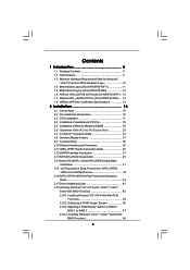
Contents 1 Introduction 5 1.1 Package Contents 5 1.2 Specifications 6 1.3 Minimum Hardware Requirement Table for Windows® VistaTM Premium 2008 and Basic Logo 10 1.4 Motherboard Layout (4Core1600P35-WiFi 11 1.5 Motherboard Layout (4Core1600P35-WiFi 12 1.6 ASRock 1394_eSATAII I/O Plus (4Core1600P35-WiFi+) . 13 1.7 ASRock 8CH_eSATAII I/O Plus (4Core1600P35-WiFi) .... 14 1.8 ASRock WiFi-802.11g Module Specifications 15 2 Installation 16 2.1 Screw Holes 16 2.2 Pre-installation Precautions 16 2.3 CPU Installation 17 2.4 Installation of Heatsink and CPU...
Contents 1 Introduction 5 1.1 Package Contents 5 1.2 Specifications 6 1.3 Minimum Hardware Requirement Table for Windows® VistaTM Premium 2008 and Basic Logo 10 1.4 Motherboard Layout (4Core1600P35-WiFi 11 1.5 Motherboard Layout (4Core1600P35-WiFi 12 1.6 ASRock 1394_eSATAII I/O Plus (4Core1600P35-WiFi+) . 13 1.7 ASRock 8CH_eSATAII I/O Plus (4Core1600P35-WiFi) .... 14 1.8 ASRock WiFi-802.11g Module Specifications 15 2 Installation 16 2.1 Screw Holes 16 2.2 Pre-installation Precautions 16 2.3 CPU Installation 17 2.4 Installation of Heatsink and CPU...

User Manual
Page 5
..., please visit our website for purchasing ASRock 4Core1600P35-WiFi+ / 4Core1600P35-WiFi motherboard, a reliable motherboard produced under ASRock's consistently stringent quality control. www.asrock.com/support/index.asp 1.1 Package Contents ASRock 4Core1600P35-WiFi+ / 4Core1600P35-WiFi Motherboard (ATX Form Factor: 12.0-in x 9.6-in, 30.5 cm x 24.4 cm) ASRock 4Core1600P35-WiFi+ / 4Core1600P35-WiFi Quick Installation Guide ASRock 4Core1600P35-WiFi+ / 4Core1600P35-WiFi Support CD ASRock WiFi-802.11g Module Operation Guide Motherboard Accessories One 80-conductor Ultra ATA 66/100/133 IDE...
..., please visit our website for purchasing ASRock 4Core1600P35-WiFi+ / 4Core1600P35-WiFi motherboard, a reliable motherboard produced under ASRock's consistently stringent quality control. www.asrock.com/support/index.asp 1.1 Package Contents ASRock 4Core1600P35-WiFi+ / 4Core1600P35-WiFi Motherboard (ATX Form Factor: 12.0-in x 9.6-in, 30.5 cm x 24.4 cm) ASRock 4Core1600P35-WiFi+ / 4Core1600P35-WiFi Quick Installation Guide ASRock 4Core1600P35-WiFi+ / 4Core1600P35-WiFi Support CD ASRock WiFi-802.11g Module Operation Guide Motherboard Accessories One 80-conductor Ultra ATA 66/100/133 IDE...

User Manual
Page 9
... module and adopt a FSB1333- Due to page 29 for proper jumper settings. Please refer to adjust the jumpers. For microphone input, this motherboard, please remove the AC power cord from your PC in advance. 2. Please read the installation guide of "Hyper Threading Technology", please check page... 56. 3. Please check the table on this motherboard, it will run at DDR3 960 if you want to page 29 for proper jumper settings. 6. About the setting of memory modules ...
... module and adopt a FSB1333- Due to page 29 for proper jumper settings. Please refer to adjust the jumpers. For microphone input, this motherboard, please remove the AC power cord from your PC in advance. 2. Please read the installation guide of "Hyper Threading Technology", please check page... 56. 3. Please check the table on this motherboard, it will run at DDR3 960 if you want to page 29 for proper jumper settings. 6. About the setting of memory modules ...
User Manual
Page 10
...refer to page 62 for detailed setup. 1.3 Minimum Hardware Requirement Table for details about eSATAII and eSATAII installation procedures. 11. WiFi header supports WiFi+AP function with 64bit VGA memory (Basic) * After June 1, 2008, all Windows® VistaTM systems are not supported... -use IDE mode under Windows® environment. While CPU overheat is not recommended to SATAII mode. ASRock website: http://www.asrock.com 14. This motherboard supports eSATAII interface, the external SATAII specification. Before you to SATAII connector directly. 10. 9. Before ...
...refer to page 62 for detailed setup. 1.3 Minimum Hardware Requirement Table for details about eSATAII and eSATAII installation procedures. 11. WiFi header supports WiFi+AP function with 64bit VGA memory (Basic) * After June 1, 2008, all Windows® VistaTM systems are not supported... -use IDE mode under Windows® environment. While CPU overheat is not recommended to SATAII mode. ASRock website: http://www.asrock.com 14. This motherboard supports eSATAII interface, the external SATAII specification. Before you to SATAII connector directly. 10. 9. Before ...
User Manual
Page 11
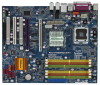
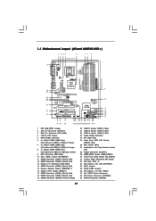
... x16 Slot (PCIE1) 37 SLI / XFIRE Power Connector 38 ATX Power Connector (ATXPWR1) 39 eSATAII Connector (eSATAII) 11 1.4 Motherboard Layout (4Core1600P35-WiFi+) 1 2 34 5 67 8 24.4cm (9.6 in) PS2 Mouse PS2 Keyboard 39 1 PS2_USB_PWR1 ATX12V1 RoHS Yorkfield Wolfdale DDR2 1066...Super I/O AUDIO CODEC PCIE1 RAID FSB2 1 1 FSB3 FSB1 1 AGI_EXPRESS1 PCI1 PCI EXPRESS 8Mb BIOS PCI2 1 WIFI PCI3 CD1 HD_AUDIO1 HDMI_SPDIF1 1 1 FLOPPY1 IR1 1 FRONT_1394 1 4Core1600P35-WiFi+ FSB1600 Dual Channel Quad Core CPU IDE1 1 CLRCMOS1 CMOS Battery Intel ICH9R SATAII_5 (Port4) SATAII_6 (Port5)...
... x16 Slot (PCIE1) 37 SLI / XFIRE Power Connector 38 ATX Power Connector (ATXPWR1) 39 eSATAII Connector (eSATAII) 11 1.4 Motherboard Layout (4Core1600P35-WiFi+) 1 2 34 5 67 8 24.4cm (9.6 in) PS2 Mouse PS2 Keyboard 39 1 PS2_USB_PWR1 ATX12V1 RoHS Yorkfield Wolfdale DDR2 1066...Super I/O AUDIO CODEC PCIE1 RAID FSB2 1 1 FSB3 FSB1 1 AGI_EXPRESS1 PCI1 PCI EXPRESS 8Mb BIOS PCI2 1 WIFI PCI3 CD1 HD_AUDIO1 HDMI_SPDIF1 1 1 FLOPPY1 IR1 1 FRONT_1394 1 4Core1600P35-WiFi+ FSB1600 Dual Channel Quad Core CPU IDE1 1 CLRCMOS1 CMOS Battery Intel ICH9R SATAII_5 (Port4) SATAII_6 (Port5)...
User Manual
Page 12
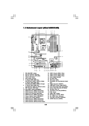
1.5 Motherboard Layout (4Core1600P35-WiFi) 1 2 34 5 24.4cm (9.6 in) 67 8 PS2 Mouse PS2 Keyboard 38 1 PS2_USB_PWR1 ATX12V1 RoHS Yorkfield Wolfdale DDR2 1066 DDR3 1333 PARALLEL PORT COM1 DDRII_3 (64 bit,...Center: FRONT Bottom: MIC IN LAN PHY Super I/O AUDIO CODEC PCIE1 RAID FSB2 1 1 FSB3 FSB1 1 AGI_EXPRESS1 PCI1 PCI EXPRESS 8Mb BIOS PCI2 1 WIFI PCI3 CD1 HD_AUDIO1 HDMI_SPDIF1 1 1 FLOPPY1 IR1 1 4Core1600P35-WiFi FSB1600 Dual Channel Quad Core CPU IDE1 1 CLRCMOS1 CMOS Battery Intel ICH9R SATAII_5 (Port4) SATAII_6 (Port5) SATAII SATAII_1 (Port0) SATAII_2 (Port1) CHA_FAN1...
1.5 Motherboard Layout (4Core1600P35-WiFi) 1 2 34 5 24.4cm (9.6 in) 67 8 PS2 Mouse PS2 Keyboard 38 1 PS2_USB_PWR1 ATX12V1 RoHS Yorkfield Wolfdale DDR2 1066 DDR3 1333 PARALLEL PORT COM1 DDRII_3 (64 bit,...Center: FRONT Bottom: MIC IN LAN PHY Super I/O AUDIO CODEC PCIE1 RAID FSB2 1 1 FSB3 FSB1 1 AGI_EXPRESS1 PCI1 PCI EXPRESS 8Mb BIOS PCI2 1 WIFI PCI3 CD1 HD_AUDIO1 HDMI_SPDIF1 1 1 FLOPPY1 IR1 1 4Core1600P35-WiFi FSB1600 Dual Channel Quad Core CPU IDE1 1 CLRCMOS1 CMOS Battery Intel ICH9R SATAII_5 (Port4) SATAII_6 (Port5) SATAII SATAII_1 (Port0) SATAII_2 (Port1) CHA_FAN1...

User Manual
Page 15
...- Indoor: 80ft (30m) Outdoor: 200ft (60m) * The range varies in the following path of ASRock motherboard support CD: ..\ ASRock WiFi-802.11g \ Vista64_Vista_XP64_XP 15 You can easily create a wireless environment and enjoy the convenience of wireless network connectivity. With...WLAN) adapter to use ASRock WiFi-802.11g module on this motherboard, please carefully read the document in different environments Number of - ASRock WiFi-802.11g omni-directional antenna LED - Standard - ASRock WiFi-802.11g Wizard If you can also read "ASRock WiFi-802.11g Module Operation...
...- Indoor: 80ft (30m) Outdoor: 200ft (60m) * The range varies in the following path of ASRock motherboard support CD: ..\ ASRock WiFi-802.11g \ Vista64_Vista_XP64_XP 15 You can easily create a wireless environment and enjoy the convenience of wireless network connectivity. With...WLAN) adapter to use ASRock WiFi-802.11g module on this motherboard, please carefully read the document in different environments Number of - ASRock WiFi-802.11g omni-directional antenna LED - Standard - ASRock WiFi-802.11g Wizard If you can also read "ASRock WiFi-802.11g Module Operation...

User Manual
Page 16
...may cause severe damage to ensure that comes with the component. Failure to do so may cause physical injuries to you install the motherboard, study the configuration of the following precautions before you install or remove any component, ensure that the power is switched off or the... or change any component, place it . Do not over-tighten the screws! Hold components by circles to secure the motherboard to static electricity, NEVER place your chassis to the motherboard, peripherals, and/or components. 16 Failure to do not touch the ICs. 4. Make sure to use a grounded wrist ...
...may cause severe damage to ensure that comes with the component. Failure to do so may cause physical injuries to you install the motherboard, study the configuration of the following precautions before you install or remove any component, ensure that the power is switched off or the... or change any component, place it . Do not over-tighten the screws! Hold components by circles to secure the motherboard to static electricity, NEVER place your chassis to the motherboard, peripherals, and/or components. 16 Failure to do not touch the ICs. 4. Make sure to use a grounded wrist ...

User Manual
Page 18
... vertical motion. Verify that the CPU is recommended to use the cap tab to assist in removal. 1. This cap must be placed if returning the motherboard for after service. While pressing down lightly on center of PnP cap to handle and avoid kicking off the PnP cap. 2. It is within the...
... vertical motion. Verify that the CPU is recommended to use the cap tab to assist in removal. 1. This cap must be placed if returning the motherboard for after service. While pressing down lightly on center of PnP cap to handle and avoid kicking off the PnP cap. 2. It is within the...
User Manual
Page 19
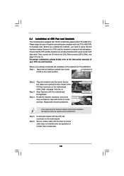
...CPU fan to the CPU_FAN connector (CPU_FAN1, see page 11/12, No. 3). Step 5. 2.4 Installation of CPU Fan and Heatsink This motherboard is an example to illustrate the installation of the heatsink for 775-LAND CPU. Please adopt the type of heatsink and cooling fan compliant...other components. 19 Connect fan header with the CPU fan connector on fastener caps with thumb to the instruction manuals of IHS on the motherboard. For proper installation, please kindly refer to install and lock. Apply thermal interface material onto center of your CPU fan and heatsink. Below...
...CPU fan to the CPU_FAN connector (CPU_FAN1, see page 11/12, No. 3). Step 5. 2.4 Installation of CPU Fan and Heatsink This motherboard is an example to illustrate the installation of the heatsink for 775-LAND CPU. Please adopt the type of heatsink and cooling fan compliant...other components. 19 Connect fan header with the CPU fan connector on fastener caps with thumb to the instruction manuals of IHS on the motherboard. For proper installation, please kindly refer to install and lock. Apply thermal interface material onto center of your CPU fan and heatsink. Below...

User Manual
Page 20
Orange slots; Green slots; see p.11/12 No.7), or identical DDR3 DIMM pair in Dual Channel B (DDRII_2 and DDRII_4; This motherboard also allows you to install identical DDR2 DIMM pair in Dual Channel A (DDRII_1 and DDRII_3; Yellow slots; see p.11/12 No. 6), identical DDR2 DIMM pair..., you have to install four DDR2 DIMMs for dual channel configuration, and please install identical DDR2 DIMMs in the slots of Memory Modules (DIMM) This motherboard provides four 240-pin DDR2 (Double Data Rate 2) DIMM slots and two 240-pin DDR3 (Double Data Rate 3) DIMM slots, and supports Dual Channel ...
Orange slots; Green slots; see p.11/12 No.7), or identical DDR3 DIMM pair in Dual Channel B (DDRII_2 and DDRII_4; This motherboard also allows you to install identical DDR2 DIMM pair in Dual Channel A (DDRII_1 and DDRII_3; Yellow slots; see p.11/12 No. 6), identical DDR2 DIMM pair..., you have to install four DDR2 DIMMs for dual channel configuration, and please install identical DDR2 DIMMs in the slots of Memory Modules (DIMM) This motherboard provides four 240-pin DDR2 (Double Data Rate 2) DIMM slots and two 240-pin DDR3 (Double Data Rate 3) DIMM slots, and supports Dual Channel ...

User Manual
Page 21
If only one memory module is installed in the DDR3 DIMM slots on this motherboard at the same time. 21 It is unable to activate the Dual Channel Memory Technology. 3. If only one memory module or three memory modules are ... activate the Dual Channel Memory Technology. DDR2 and DDR3 memory modules cannot be damaged. 5. otherwise, this motherboard and DIMM may be installed on this motherboard, it is NOT installed in the DDR2 DIMM slots on this motherboard, it is not allowed to activate the Dual Channel Memory Technology . 4. If a pair of memory modules...
If only one memory module is installed in the DDR3 DIMM slots on this motherboard at the same time. 21 It is unable to activate the Dual Channel Memory Technology. 3. If only one memory module or three memory modules are ... activate the Dual Channel Memory Technology. DDR2 and DDR3 memory modules cannot be damaged. 5. otherwise, this motherboard and DIMM may be installed on this motherboard, it is NOT installed in the DDR2 DIMM slots on this motherboard, it is not allowed to activate the Dual Channel Memory Technology . 4. If a pair of memory modules...

User Manual
Page 22
... orientation. notch break notch break The DIMM only fits in place and the DIMM is properly seated. 22 Installing a DIMM Please make sure to the motherboard and the DIMM if you force the DIMM into the slot until the retaining clips at incorrect orientation. Step 1. It will cause permanent damage to...
... orientation. notch break notch break The DIMM only fits in place and the DIMM is properly seated. 22 Installing a DIMM Please make sure to the motherboard and the DIMM if you force the DIMM into the slot until the retaining clips at incorrect orientation. Step 1. It will cause permanent damage to...
User Manual
Page 23
... installation. PCI slots: PCI slots are 3 PCI slots, 1 PCI Express slot, and 1 AGI Express slot (PCI Express x4) on this motherboard, please install it on the slot. PCIE slots: PCIE1 (PCIE x16 slot) is used for ATITM CrossFireTM driver updates. 23 If you intend... to the chassis with screws. 2.7 CrossFireTM Operation Guide This motherboard supports CrossFireTM feature. Fasten the card to use . Align the card connector with intelligent software design and an innovative interconnect mechanism, CrossFireTM ...
... installation. PCI slots: PCI slots are 3 PCI slots, 1 PCI Express slot, and 1 AGI Express slot (PCI Express x4) on this motherboard, please install it on the slot. PCIE slots: PCIE1 (PCIE x16 slot) is used for ATITM CrossFireTM driver updates. 23 If you intend... to the chassis with screws. 2.7 CrossFireTM Operation Guide This motherboard supports CrossFireTM feature. Fasten the card to use . Align the card connector with intelligent software design and an innovative interconnect mechanism, CrossFireTM ...

User Manual
Page 24
...CrossFireTM cards that ATITM has released or will operate as the example graphics card. Connect to SLI/XFIRE Power connector on this motherboard. If you install. Enjoy the benefit of its partners. Please refer to below procedures, we use 500-Watt power supply or... they will not see the performance benefits of CrossFireTM feature. 24 All three CrossFireTM components, a CrossFireTM Ready graphics card, a CrossFireTM Ready motherboard and a CrossFireTM Edition co-processor graphics card, must be installed correctly to benefit from the same series, or two CrossFireTM Ready cards....
...CrossFireTM cards that ATITM has released or will operate as the example graphics card. Connect to SLI/XFIRE Power connector on this motherboard. If you install. Enjoy the benefit of its partners. Please refer to below procedures, we use 500-Watt power supply or... they will not see the performance benefits of CrossFireTM feature. 24 All three CrossFireTM components, a CrossFireTM Ready graphics card, a CrossFireTM Ready motherboard and a CrossFireTM Edition co-processor graphics card, must be installed correctly to benefit from the same series, or two CrossFireTM Ready cards....

User Manual
Page 25
... the Radeon graphics card on the top of Radeon graphics cards. (CrossFireTM Bridge is provided with the graphics card you purchase, not bundled with this motherboard. For the proper installation procedures, please refer to D-Sub adapter.) 25 Step 4. For the proper installation procedures, please refer to your graphics card vendor for...
... the Radeon graphics card on the top of Radeon graphics cards. (CrossFireTM Bridge is provided with the graphics card you purchase, not bundled with this motherboard. For the proper installation procedures, please refer to D-Sub adapter.) 25 Step 4. For the proper installation procedures, please refer to your graphics card vendor for...

