
User Manual
Page 6
LGA 775 for Intel® CoreTM 2 Extreme / CoreTM 2 Quad / CoreTM 2 Duo / Pentium...- ATX Form Factor: 12.0-in x 9.6-in, 30.5 cm x 24.4 cm - Supports Hyper-Threading Technology (see CAUTION 7) 4Core1600P35-WiFi - 7.1 CH Windows® VistaTM Premium Level HD Audio with 110dB dynamic range (ALC890 Audio Codec) - Supports EM64T CPU - Support... CrossFireTM - 1 x PCI Express x16 slot - 1 x AGI Express slot (PCI Express x4) - 3 x PCI slots 4Core1600P35-WiFi+ - 7.1 CH Windows® VistaTM Premium Level HD Audio with 110dB dynamic range (ALC890 Audio Codec) - DAC with Content Protection - Supports ...
LGA 775 for Intel® CoreTM 2 Extreme / CoreTM 2 Quad / CoreTM 2 Duo / Pentium...- ATX Form Factor: 12.0-in x 9.6-in, 30.5 cm x 24.4 cm - Supports Hyper-Threading Technology (see CAUTION 7) 4Core1600P35-WiFi - 7.1 CH Windows® VistaTM Premium Level HD Audio with 110dB dynamic range (ALC890 Audio Codec) - Supports EM64T CPU - Support... CrossFireTM - 1 x PCI Express x16 slot - 1 x AGI Express slot (PCI Express x4) - 3 x PCI slots 4Core1600P35-WiFi+ - 7.1 CH Windows® VistaTM Premium Level HD Audio with 110dB dynamic range (ALC890 Audio Codec) - DAC with Content Protection - Supports ...
User Manual
Page 11
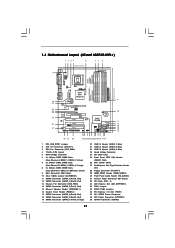
... FSB3 Jumpers 36 PCI Express x16 Slot (PCIE1) 37 SLI / XFIRE Power Connector 38 ATX Power Connector (ATXPWR1) 39 eSATAII Connector (eSATAII) 11 1.4 Motherboard Layout (4Core1600P35-WiFi+) 1 2 34 5 67 8 24.4cm (9.6 in) PS2 Mouse PS2 Keyboard 39 1 PS2_USB_PWR1 ATX12V1 RoHS Yorkfield Wolfdale DDR2 1066 DDR3 1333 PARALLEL PORT COM1 DDRII_3 ...14 15 16 30 29 28 27 26 2524 23 22212019 1817 1 PS2_USB_PWR1 Jumper 2 ATX 12V Connector (ATX12V1) 3 CPU Fan Connector (CPU_FAN1) 4 775-Pin CPU Socket 5 North Bridge Controller 6 2 x 240-pin DDR2 DIMM Slots (Dual Channel A: DDRII_1, DDRII_3;
... FSB3 Jumpers 36 PCI Express x16 Slot (PCIE1) 37 SLI / XFIRE Power Connector 38 ATX Power Connector (ATXPWR1) 39 eSATAII Connector (eSATAII) 11 1.4 Motherboard Layout (4Core1600P35-WiFi+) 1 2 34 5 67 8 24.4cm (9.6 in) PS2 Mouse PS2 Keyboard 39 1 PS2_USB_PWR1 ATX12V1 RoHS Yorkfield Wolfdale DDR2 1066 DDR3 1333 PARALLEL PORT COM1 DDRII_3 ...14 15 16 30 29 28 27 26 2524 23 22212019 1817 1 PS2_USB_PWR1 Jumper 2 ATX 12V Connector (ATX12V1) 3 CPU Fan Connector (CPU_FAN1) 4 775-Pin CPU Socket 5 North Bridge Controller 6 2 x 240-pin DDR2 DIMM Slots (Dual Channel A: DDRII_1, DDRII_3;
User Manual
Page 12
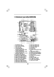
...LAN PHY Super I/O AUDIO CODEC PCIE1 RAID FSB2 1 1 FSB3 FSB1 1 AGI_EXPRESS1 PCI1 PCI EXPRESS 8Mb BIOS PCI2 1 WIFI PCI3 CD1 HD_AUDIO1 HDMI_SPDIF1 1 1 FLOPPY1 IR1 1 4Core1600P35-WiFi FSB1600 Dual Channel Quad Core CPU IDE1 1 CLRCMOS1 CMOS Battery Intel ICH9R SATAII_5 (Port4) SATAII_6 (Port5) SATAII SATAII_1 (... 15 16 29 28 27 26 25 24 23 22212019 1817 1 PS2_USB_PWR1 Jumper 2 ATX 12V Connector (ATX12V1) 3 CPU Fan Connector (CPU_FAN1) 4 775-Pin CPU Socket 5 North Bridge Controller 6 2 x 240-pin DDR2 DIMM Slots (Dual Channel A: DDRII_1, DDRII_3; Green) 9 IDE1 Connector (IDE1...
...LAN PHY Super I/O AUDIO CODEC PCIE1 RAID FSB2 1 1 FSB3 FSB1 1 AGI_EXPRESS1 PCI1 PCI EXPRESS 8Mb BIOS PCI2 1 WIFI PCI3 CD1 HD_AUDIO1 HDMI_SPDIF1 1 1 FLOPPY1 IR1 1 4Core1600P35-WiFi FSB1600 Dual Channel Quad Core CPU IDE1 1 CLRCMOS1 CMOS Battery Intel ICH9R SATAII_5 (Port4) SATAII_6 (Port5) SATAII SATAII_1 (... 15 16 29 28 27 26 25 24 23 22212019 1817 1 PS2_USB_PWR1 Jumper 2 ATX 12V Connector (ATX12V1) 3 CPU Fan Connector (CPU_FAN1) 4 775-Pin CPU Socket 5 North Bridge Controller 6 2 x 240-pin DDR2 DIMM Slots (Dual Channel A: DDRII_1, DDRII_3; Green) 9 IDE1 Connector (IDE1...

User Manual
Page 17
... Socket 17 black line black line Step 1-2. Rotate the load lever to fully open position at approximately 135 degrees. Insert the 775-LAND CPU: Step 2-1. Do not force to insert the CPU into the socket, please check if the CPU surface is unclean or if there is ... the two orientation key notches. Orient the CPU with black lines. 2.3 CPU Installation For the installation of Intel 775-LAND CPU, please follow the steps below. 775-Pin Socket Overview Before you insert the 775-LAND CPU into the socket if above situation is any bent pin on the hook to clear retention...
... Socket 17 black line black line Step 1-2. Rotate the load lever to fully open position at approximately 135 degrees. Insert the 775-LAND CPU: Step 2-1. Do not force to insert the CPU into the socket, please check if the CPU surface is unclean or if there is ... the two orientation key notches. Orient the CPU with black lines. 2.3 CPU Installation For the installation of Intel 775-LAND CPU, please follow the steps below. 775-Pin Socket Overview Before you insert the 775-LAND CPU into the socket if above situation is any bent pin on the hook to clear retention...
User Manual
Page 19
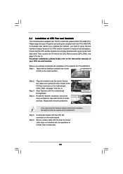
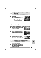
... to improve heat dissipation. Step 6. For proper installation, please kindly refer to the instruction manuals of the heatsink for 775-LAND CPU. Below is equipped with Intel 775-LAND CPU to dissipate heat. Apply thermal interface material onto center of heatsink and cooling fan compliant with...interfere with the CPU fan connector on the socket surface. Step 4. Repeat with each other components. 19 Ensure that supports Intel 775-LAND CPU. 2.4 Installation of CPU Fan and Heatsink This motherboard is an example to illustrate the installation of your CPU fan and heatsink...
... to improve heat dissipation. Step 6. For proper installation, please kindly refer to the instruction manuals of the heatsink for 775-LAND CPU. Below is equipped with Intel 775-LAND CPU to dissipate heat. Apply thermal interface material onto center of heatsink and cooling fan compliant with...interfere with the CPU fan connector on the socket surface. Step 4. Repeat with each other components. 19 Ensure that supports Intel 775-LAND CPU. 2.4 Installation of CPU Fan and Heatsink This motherboard is an example to illustrate the installation of your CPU fan and heatsink...

Quick Installation Guide
Page 2
... Red) 38 ATX Power Connector (ATXPWR1) 19 SATAII Connector (SATAII_6 (Port5), Orange) 39 eSATAII Connector (eSATAII) 2 ASRock 4Core1600P35-WiFi+ / 4Core1600P35-WiFi Motherboard Motherboard Layout (4Core1600P35-WiFi+) English 1 PS2_USB_PWR1 Jumper 20 USB 2.0 Header (USB6_7, Blue) 2 ATX 12V Connector (ATX12V1) 21 USB 2.0 Header ...(USB4_5, Blue) 3 CPU Fan Connector (CPU_FAN1) 22 USB 2.0 Header (USB8_9, Blue) 4 775-Pin CPU Socket 23...
... Red) 38 ATX Power Connector (ATXPWR1) 19 SATAII Connector (SATAII_6 (Port5), Orange) 39 eSATAII Connector (eSATAII) 2 ASRock 4Core1600P35-WiFi+ / 4Core1600P35-WiFi Motherboard Motherboard Layout (4Core1600P35-WiFi+) English 1 PS2_USB_PWR1 Jumper 20 USB 2.0 Header (USB6_7, Blue) 2 ATX 12V Connector (ATX12V1) 21 USB 2.0 Header ...(USB4_5, Blue) 3 CPU Fan Connector (CPU_FAN1) 22 USB 2.0 Header (USB8_9, Blue) 4 775-Pin CPU Socket 23...

Quick Installation Guide
Page 3
...4Core1600P35-WiFi) English 1 PS2_USB_PWR1 Jumper 20 USB 2.0 Header (USB6_7, Blue) 2 ATX 12V Connector (ATX12V1) 21 USB 2.0 Header (USB4_5, Blue) 3 CPU Fan Connector (CPU_FAN1) 22 USB 2.0 Header (USB8_9, Blue) 4 775-Pin CPU Socket 23 South Bridge Controller 5 North Bridge Controller 24 SPI BIOS Chip 6 2 x 240-pin DDR2 DIMM Slots 25 WiFi Header (WiFi... (Port3), Red) 19 SATAII Connector (SATAII_6 (Port5), Orange) 3 ASRock 4Core1600P35-WiFi+ / 4Core1600P35-WiFi Motherboard Yellow) 26 DeskExpress Hot Plug Detection Header 7 2 x 240-pin DDR2 DIMM Slots (IR1) (Dual Channel ...
...4Core1600P35-WiFi) English 1 PS2_USB_PWR1 Jumper 20 USB 2.0 Header (USB6_7, Blue) 2 ATX 12V Connector (ATX12V1) 21 USB 2.0 Header (USB4_5, Blue) 3 CPU Fan Connector (CPU_FAN1) 22 USB 2.0 Header (USB8_9, Blue) 4 775-Pin CPU Socket 23 South Bridge Controller 5 North Bridge Controller 24 SPI BIOS Chip 6 2 x 240-pin DDR2 DIMM Slots 25 WiFi Header (WiFi... (Port3), Red) 19 SATAII Connector (SATAII_6 (Port5), Orange) 3 ASRock 4Core1600P35-WiFi+ / 4Core1600P35-WiFi Motherboard Yellow) 26 DeskExpress Hot Plug Detection Header 7 2 x 240-pin DDR2 DIMM Slots (IR1) (Dual Channel ...

Quick Installation Guide
Page 8
Realtek RTL8111B/RTL8111C - LGA 775 for Intel® CoreTM 2 Extreme / CoreTM 2 Quad / CoreTM 2 Duo / Pentium® Dual Core / Celeron®, supporting Penryn Quad Core Yorkfield and Dual Core Wolfdale processors - Compatible with Content Protection - Dual Channel DDR3/DDR2 Memory Technology (see CAUTION 3) - Supports Wake-On-LAN English 8 ASRock 4Core1600P35-WiFi+ / 4Core1600P35-WiFi Motherboard All Solid Capacitor design...
Realtek RTL8111B/RTL8111C - LGA 775 for Intel® CoreTM 2 Extreme / CoreTM 2 Quad / CoreTM 2 Duo / Pentium® Dual Core / Celeron®, supporting Penryn Quad Core Yorkfield and Dual Core Wolfdale processors - Compatible with Content Protection - Dual Channel DDR3/DDR2 Memory Technology (see CAUTION 3) - Supports Wake-On-LAN English 8 ASRock 4Core1600P35-WiFi+ / 4Core1600P35-WiFi Motherboard All Solid Capacitor design...

Quick Installation Guide
Page 13
...Otherwise, the CPU will be seriously damaged. 13 ASRock 4Core1600P35-WiFi+ / 4Core1600P35-WiFi Motherboard English Failure to do so may damage the motherboard. 2.1 CPU Installation For the installation of the following precautions before you insert the 775-LAND CPU into the socket, please check if ... grounded object before touching any motherboard settings. 1. Installation Pre-installation Precautions Take note of Intel 775-LAND CPU, please follow the steps below. 775-Pin Socket Overview Before you install motherboard components or change any component. Doing so may cause severe...
...Otherwise, the CPU will be seriously damaged. 13 ASRock 4Core1600P35-WiFi+ / 4Core1600P35-WiFi Motherboard English Failure to do so may damage the motherboard. 2.1 CPU Installation For the installation of the following precautions before you insert the 775-LAND CPU into the socket, please check if ... grounded object before touching any motherboard settings. 1. Installation Pre-installation Precautions Take note of Intel 775-LAND CPU, please follow the steps below. 775-Pin Socket Overview Before you install motherboard components or change any component. Doing so may cause severe...

Quick Installation Guide
Page 14
... notches of the CPU with right hand thumb and peel the cap from the socket while pressing on the hook to assist in removal. 14 ASRock 4Core1600P35-WiFi+ / 4Core1600P35-WiFi Motherboard Insert the 775-LAND CPU: Step 2-1. Step 2-4. Step 2. Rotate the load lever to the orient keys. Step 3.
... notches of the CPU with right hand thumb and peel the cap from the socket while pressing on the hook to assist in removal. 14 ASRock 4Core1600P35-WiFi+ / 4Core1600P35-WiFi Motherboard Insert the 775-LAND CPU: Step 2-1. Step 2-4. Step 2. Rotate the load lever to the orient keys. Step 3.
Quick Installation Guide
Page 15
...to handle and avoid kicking off the PnP cap. 2. Step 4-2. Step 3. Step 4. Align fasteners with fan operation or contact other components. 15 ASRock 4Core1600P35-WiFi+ / 4Core1600P35-WiFi Motherboard English Secure load lever with load plate tab under retention tab of load lever. 2.2 Installation of the heatsink for after service. Below is recommended... the IHS. While pressing down the fasteners without rotating them clockwise, the heatsink cannot be placed if returning the motherboard for 775-LAND CPU. Ensure fan cables are oriented on the socket surface. Step 6.
...to handle and avoid kicking off the PnP cap. 2. Step 4-2. Step 3. Step 4. Align fasteners with fan operation or contact other components. 15 ASRock 4Core1600P35-WiFi+ / 4Core1600P35-WiFi Motherboard English Secure load lever with load plate tab under retention tab of load lever. 2.2 Installation of the heatsink for after service. Below is recommended... the IHS. While pressing down the fasteners without rotating them clockwise, the heatsink cannot be placed if returning the motherboard for 775-LAND CPU. Ensure fan cables are oriented on the socket surface. Step 6.