
User Manual
Page 3
... Contents 5 1.2 Specifications 6 1.3 Minimum Hardware Requirement Table for Windows® VistaTM Premium 2007 and Basic Logo 9 1.4 Motherboard Layout 10 1.5 ASRock 6CH I/O 11 2 Installation 12 2.1 Screw Holes 12 2.2 Pre-installation Precautions 12 2.3 CPU Installation 13 2.4 Installation of Heatsink and CPU fan... Installation of Memory Modules (DIMM 16 2.6 Expansion Slots (PCI and PCI Express Slots 18 2.7 DVI Graphics-SI Card Installation Guide 19 2.8 Jumpers Setup 21 2.9 Onboard Headers and Connectors 23 2.10 SATAII Hard Disk Setup Guide 27 2.11 Serial ATA (SATA) / Serial ATAII...
... Contents 5 1.2 Specifications 6 1.3 Minimum Hardware Requirement Table for Windows® VistaTM Premium 2007 and Basic Logo 9 1.4 Motherboard Layout 10 1.5 ASRock 6CH I/O 11 2 Installation 12 2.1 Screw Holes 12 2.2 Pre-installation Precautions 12 2.3 CPU Installation 13 2.4 Installation of Heatsink and CPU fan... Installation of Memory Modules (DIMM 16 2.6 Expansion Slots (PCI and PCI Express Slots 18 2.7 DVI Graphics-SI Card Installation Guide 19 2.8 Jumpers Setup 21 2.9 Onboard Headers and Connectors 23 2.10 SATAII Hard Disk Setup Guide 27 2.11 Serial ATA (SATA) / Serial ATAII...

User Manual
Page 7
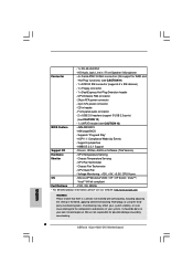
...Support CD - Chassis Fan Tachometer - FCC, CE, WHQL * For detailed product information, please visit our website: http://www.asrock.com WARNING Please realize that there is a certain risk involved with overclocking, including adjusting the setting in header - CD in ... or using the thirdparty overclocking tools. CPU/Chassis FAN connector - 24 pin ATX power connector - 4 pin 12V power connector - Chassis Temperature Sensing - HD Audio Jack: Line in / Front Speaker / Microphone Connector - 4 x Serial ATAII 3.0Gb/s connectors (No support for possible damage caused by overclocking. 7...
...Support CD - Chassis Fan Tachometer - FCC, CE, WHQL * For detailed product information, please visit our website: http://www.asrock.com WARNING Please realize that there is a certain risk involved with overclocking, including adjusting the setting in header - CD in ... or using the thirdparty overclocking tools. CPU/Chassis FAN connector - 24 pin ATX power connector - 4 pin 12V power connector - Chassis Temperature Sensing - HD Audio Jack: Line in / Front Speaker / Microphone Connector - 4 x Serial ATAII 3.0Gb/s connectors (No support for possible damage caused by overclocking. 7...

User Manual
Page 8
... other than 4GB for the reservation for proper jumper settings. 2. Before you use a FSB1600- Before installing SATAII hard disk to SATAII connector, please read "Untied Overclocking Technology" on page 26 to adjust your SATAII hard disk drive to adjust the jumpers as well. You ...page 27 for details. 4. Due to page 21 for system usage under Windows® XP and Windows® VistaTM. mended to SATAII connector directly. 8 Please check Intel® website for the CPU FSB frequency and its corresponding memory support frequency. Under this motherboard, please read...
... other than 4GB for the reservation for proper jumper settings. 2. Before you use a FSB1600- Before installing SATAII hard disk to SATAII connector, please read "Untied Overclocking Technology" on page 26 to adjust your SATAII hard disk drive to adjust the jumpers as well. You ...page 27 for details. 4. Due to page 21 for system usage under Windows® XP and Windows® VistaTM. mended to SATAII connector directly. 8 Please check Intel® website for the CPU FSB frequency and its corresponding memory support frequency. Under this motherboard, please read...

User Manual
Page 10
... Top: RJ-45 Super I/O ATXPWR1 LAN PHY CD1 HD_AUDIO1 1 PCIE1 FD 1 PCIE2/DE SATAII PCI1 AUDIO CODEC WIFI/E 1 PCI2 FLOPPY1 RoHS 4Core1600-DVI Quad Core CPU Intel G31 Chipset PCI EXPRESS CHA_FAN1 Intel ICH7 4Mb BIOS IDE1 USB4_5 1 USB6 1 SATAII_3 SATAII_1 SATAII_4 SATAII_2 SPEAKER1 1 PLED PWRBTN ... PANEL1 FSB1600 23 22 21 20 19 18 1716 15 14 24.4cm (9.6 in) 9 10 11 12 13 1 PS2_USB_PWR1 Jumper 2 CPU Fan Connector (CPU_FAN1) 3 ATX 12V Connector (ATX12V1) 4 775-Pin CPU Socket 5 North Bridge Controller 6 Clear CMOS Jumper (CLRCMOS1) 7 2 x 240-pin DDR2 DIMM Slots (Dual Channel...
... Top: RJ-45 Super I/O ATXPWR1 LAN PHY CD1 HD_AUDIO1 1 PCIE1 FD 1 PCIE2/DE SATAII PCI1 AUDIO CODEC WIFI/E 1 PCI2 FLOPPY1 RoHS 4Core1600-DVI Quad Core CPU Intel G31 Chipset PCI EXPRESS CHA_FAN1 Intel ICH7 4Mb BIOS IDE1 USB4_5 1 USB6 1 SATAII_3 SATAII_1 SATAII_4 SATAII_2 SPEAKER1 1 PLED PWRBTN ... PANEL1 FSB1600 23 22 21 20 19 18 1716 15 14 24.4cm (9.6 in) 9 10 11 12 13 1 PS2_USB_PWR1 Jumper 2 CPU Fan Connector (CPU_FAN1) 3 ATX 12V Connector (ATX12V1) 4 775-Pin CPU Socket 5 North Bridge Controller 6 Clear CMOS Jumper (CLRCMOS1) 7 2 x 240-pin DDR2 DIMM Slots (Dual Channel...

User Manual
Page 15
...page 10, No. 2). Apply thermal interface material onto center of heatsink and cooling fan compliant with Intel 775-LAND CPU to the CPU fan connector on the motherboard. Step 3. Step 4. Repeat with the motherboard throughholes. Step 5. Before you installed the heatsink, you press down on the ...the socket. Ensure fan cables are securely fastened and in good contact with thumb to ensure cable does not interfere with the CPU fan connector on the motherboard (CPU_FAN1, see page 10, No. 2). Align fasteners with remaining fasteners. Connect fan header with fan operation or contact...
...page 10, No. 2). Apply thermal interface material onto center of heatsink and cooling fan compliant with Intel 775-LAND CPU to the CPU fan connector on the motherboard. Step 3. Step 4. Repeat with the motherboard throughholes. Step 5. Before you installed the heatsink, you press down on the ...the socket. Ensure fan cables are securely fastened and in good contact with thumb to ensure cable does not interfere with the CPU fan connector on the motherboard (CPU_FAN1, see page 10, No. 2). Align fasteners with remaining fasteners. Connect fan header with fan operation or contact...

User Manual
Page 18
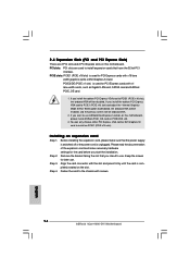
...that you install the add-on PCIE2/DE slot. 3. If you intend to use ASRock DeskExpress function on this motherboard. Keep the screws for PCI Express cards with x16 lane width graphics cards or DVI Graphics-SI card. Fasten the card to the chassis with the slot and press ...Graphics Mode Select" BIOS option to [Enabled], the onboard VGA will be enabled, and the primary screen will be onboard VGA. 2. Align the card connector with screws. 18 Step 4. PCIE slots: PCIE1 (PCIE x16 slot) is unplugged. Please read the documentation of the expansion card and make sure that...
...that you install the add-on PCIE2/DE slot. 3. If you intend to use ASRock DeskExpress function on this motherboard. Keep the screws for PCI Express cards with x16 lane width graphics cards or DVI Graphics-SI card. Fasten the card to the chassis with the slot and press ...Graphics Mode Select" BIOS option to [Enabled], the onboard VGA will be enabled, and the primary screen will be onboard VGA. 2. Align the card connector with screws. 18 Step 4. PCIE slots: PCIE1 (PCIE x16 slot) is unplugged. Please read the documentation of the expansion card and make sure that...

User Manual
Page 19
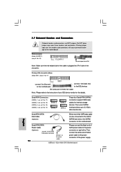
...this motherboard. DVI-D connector of DVI-D monitor 19 DVI-D output connector of DVI Graphics-SI card Step 1. Connect the DVI-D monitor to the DVI-D output connector of DVI Graphics-SI card which is inserted to PCIE1 (PCIE x16 slot) on this motherboard provides users with dual VGA output support: DVI-D and D-Sub...slot) on page 18 for proper installation of DVI Graphics-SI card. Please refer to PCIE1 (PCIE x16 slot). DVI Graphics-SI card Step 2. Install the DVI Graphics-SI card to below procedures for details. 2.7 DVI Graphics-SI Card Installation Guide With the onboard VGA...
...this motherboard. DVI-D connector of DVI-D monitor 19 DVI-D output connector of DVI Graphics-SI card Step 1. Connect the DVI-D monitor to the DVI-D output connector of DVI Graphics-SI card which is inserted to PCIE1 (PCIE x16 slot) on this motherboard provides users with dual VGA output support: DVI-D and D-Sub...slot) on page 18 for proper installation of DVI Graphics-SI card. Please refer to PCIE1 (PCIE x16 slot). DVI Graphics-SI card Step 2. Install the DVI Graphics-SI card to below procedures for details. 2.7 DVI Graphics-SI Card Installation Guide With the onboard VGA...

User Manual
Page 22
... SATAII_4 SATAII_2 Serial ATA (SATA) Data Cable (Optional) Serial ATA (SATA) Power Cable (Optional) connect to the SATA HDD power connector connect to the power connector of your IDE device vendor for internal storage devices. Either end of the motherboard! Placing jumper caps over these headers and... plugged into Pin1 side of SATA power cable to the SATA / SATAII hard disk or the SATAII connector on each drive. 2.9 Onboard Headers and Connectors Onboard headers and connectors are NOT jumpers. The current SATAII interface allows up to the instruction of the power supply. 22...
... SATAII_4 SATAII_2 Serial ATA (SATA) Data Cable (Optional) Serial ATA (SATA) Power Cable (Optional) connect to the SATA HDD power connector connect to the power connector of your IDE device vendor for internal storage devices. Either end of the motherboard! Placing jumper caps over these headers and... plugged into Pin1 side of SATA power cable to the SATA / SATAII hard disk or the SATAII connector on each drive. 2.9 Onboard Headers and Connectors Onboard headers and connectors are NOT jumpers. The current SATAII interface allows up to the instruction of the power supply. 22...

User Manual
Page 23
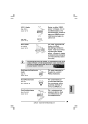
...detection function for front panel audio cable that allows convenient connection and control of wireless network connectivity. Internal Audio Connectors (4-pin CD1) (CD1: see p.10 No. 26) This connector allows you to this picture for proper installation. It allows you don't plan to use wireless local area ... Audio Header (9-pin HD_AUDIO1) (see p.10 No. 25) GND PRESENCE# MIC_RET OUT_RET 1 OUT2_L J_SENSE OUT2_R MIC2_R MIC2_L 23 This is an interface for ASRock DeskExpress. WiFi/E Header (15-pin WIFI/E) (see p.10 No. 23) USB+5V_2 TXN TXP GND2 PCIE_RST# +3SVB RXN RXP 1 GND1 D0-D0...
...detection function for front panel audio cable that allows convenient connection and control of wireless network connectivity. Internal Audio Connectors (4-pin CD1) (CD1: see p.10 No. 26) This connector allows you to this picture for proper installation. It allows you don't plan to use wireless local area ... Audio Header (9-pin HD_AUDIO1) (see p.10 No. 25) GND PRESENCE# MIC_RET OUT_RET 1 OUT2_L J_SENSE OUT2_R MIC2_R MIC2_L 23 This is an interface for ASRock DeskExpress. WiFi/E Header (15-pin WIFI/E) (see p.10 No. 23) USB+5V_2 TXN TXP GND2 PCIE_RST# +3SVB RXN RXP 1 GND1 D0-D0...

User Manual
Page 24
...Chipset Configuration. System Panel Header (9-pin PANEL1) (see p.10 No. 13) Chassis Speaker Header (4-pin SPEAKER 1) (see p.10 No. 12) Chassis Fan Connector (3-pin CHA_FAN1) (see p.10 No. 2) 4 3 2 1 GND +12V CPU_FAN_SPEED FAN_SPEED_CONTROL Please connect a CPU fan cable to this header. Connect Audio_R ...OS: Click the right-top "Folder" icon , choose "Disable front panel jack detection", and save the change by clicking "OK". CPU Fan Connector (4-pin CPU_FAN1) (see p.10 No. 21) PLED+ PLEDPWRBTN# GND 1 DUMMY RESET# GND HDLEDHDLED+ This header accommodates several system front panel ...
...Chipset Configuration. System Panel Header (9-pin PANEL1) (see p.10 No. 13) Chassis Speaker Header (4-pin SPEAKER 1) (see p.10 No. 12) Chassis Fan Connector (3-pin CHA_FAN1) (see p.10 No. 2) 4 3 2 1 GND +12V CPU_FAN_SPEED FAN_SPEED_CONTROL Please connect a CPU fan cable to this header. Connect Audio_R ...OS: Click the right-top "Folder" icon , choose "Disable front panel jack detection", and save the change by clicking "OK". CPU Fan Connector (4-pin CPU_FAN1) (see p.10 No. 21) PLED+ PLEDPWRBTN# GND 1 DUMMY RESET# GND HDLEDHDLED+ This header accommodates several system front panel ...

User Manual
Page 25
... with Pin 1 and Pin 13. 24 13 20-Pin ATX Power Supply Installation 12 1 ATX 12V Connector (4-pin ATX12V1) (see p.10, No. 29) 12 Please connect an ATX power 13 supply to this connector. 1 Though this motherboard, please connect it can work if you plan to connect the 3-Pin CPU ...fan to the CPU fan connector on this motherboard provides 24-pin ATX power connector, it to this motherboard provides 4-Pin CPU fan (Quiet Fan) support, the 3-Pin CPU fan still can still work successfully even...
... with Pin 1 and Pin 13. 24 13 20-Pin ATX Power Supply Installation 12 1 ATX 12V Connector (4-pin ATX12V1) (see p.10, No. 29) 12 Please connect an ATX power 13 supply to this connector. 1 Though this motherboard, please connect it can work if you plan to connect the 3-Pin CPU ...fan to the CPU fan connector on this motherboard provides 24-pin ATX power connector, it to this motherboard provides 4-Pin CPU fan (Quiet Fan) support, the 3-Pin CPU fan still can still work successfully even...

User Manual
Page 27
... the SATA / SATAII hard disks into the drive bays of BIOS setup to set the selection from up to bottom side to the motherboard's SATAII connector.
... the SATA / SATAII hard disks into the drive bays of BIOS setup to set the selection from up to bottom side to the motherboard's SATAII connector.

Quick Installation Guide
Page 2
...) 27 PCI Express x1 Slot (PCIE2/DE) 28 PCI Express x16 Slot (PCIE1) 29 ATX Power Connector (ATXPWR1) 30 DeskExpress Hot Plug Detection Header (IR1) 2 ASRock 4Core1600-DVI Motherboard Motherboard Layout English 1 PS2_USB_PWR1 Jumper 2 CPU Fan Connector (CPU_FAN1) 3 ATX 12V Connector (ATX12V1) 4 775-Pin CPU Socket 5 North Bridge Controller 6 Clear CMOS Jumper (CLRCMOS1) 7 2 x 240-pin DDR2...
...) 27 PCI Express x1 Slot (PCIE2/DE) 28 PCI Express x16 Slot (PCIE1) 29 ATX Power Connector (ATXPWR1) 30 DeskExpress Hot Plug Detection Header (IR1) 2 ASRock 4Core1600-DVI Motherboard Motherboard Layout English 1 PS2_USB_PWR1 Jumper 2 CPU Fan Connector (CPU_FAN1) 3 ATX 12V Connector (ATX12V1) 4 775-Pin CPU Socket 5 North Bridge Controller 6 Clear CMOS Jumper (CLRCMOS1) 7 2 x 240-pin DDR2...
Quick Installation Guide
Page 6
... 1 x ATA100 IDE connector (supports 2 x IDE devices) - 1 x Floppy connector - 1 x DeskExpress Hot Plug Detection header - AMBIOS 2.3.1 Support Support CD - Microsoft® Windows® 2000 / XP / XP 64-bit / VistaTM / VistaTM 64-bit compliant Certifications - English 6 ASRock 4Core1600-DVI Motherboard Drivers, Utilities, AntiVirus...Temperature Sensing - FCC, CE, WHQL * For detailed product information, please visit our website: http://www.asrock.com WARNING Please realize that there is a certain risk involved with overclocking, including adjusting the setting in header...
... 1 x ATA100 IDE connector (supports 2 x IDE devices) - 1 x Floppy connector - 1 x DeskExpress Hot Plug Detection header - AMBIOS 2.3.1 Support Support CD - Microsoft® Windows® 2000 / XP / XP 64-bit / VistaTM / VistaTM 64-bit compliant Certifications - English 6 ASRock 4Core1600-DVI Motherboard Drivers, Utilities, AntiVirus...Temperature Sensing - FCC, CE, WHQL * For detailed product information, please visit our website: http://www.asrock.com WARNING Please realize that there is a certain risk involved with overclocking, including adjusting the setting in header...

Quick Installation Guide
Page 7
... Overclocking Technology" on this motherboard offers stepless control, it is subject to SATAII connector, please read the "SATAII Hard Disk Setup Guide" on the motherboard functions properly and unplug the power cord, then plug it back again. English 7 ASRock 4Core1600-DVI Motherboard If you install the PC system. 10. Before you resume the system...
... Overclocking Technology" on this motherboard offers stepless control, it is subject to SATAII connector, please read the "SATAII Hard Disk Setup Guide" on the motherboard functions properly and unplug the power cord, then plug it back again. English 7 ASRock 4Core1600-DVI Motherboard If you install the PC system. 10. Before you resume the system...

Quick Installation Guide
Page 11
...after service. Rotate the fastener clockwise, then press down on the socket surface. It is an example to the CPU fan connector on the motherboard. Ensure fan cables are oriented on side closest to illustrate the installation of IHS on fastener caps with the ...heatsink cannot be placed if returning the motherboard for 775-LAND CPU. Step 1. Align fasteners with fan operation or contact other components. 11 ASRock 4Core1600-DVI Motherboard English This cap must be secured on the motherboard (CPU_FAN1, see page 2, No. 2). Below is recommended to use the cap tab...
...after service. Rotate the fastener clockwise, then press down on the socket surface. It is an example to the CPU fan connector on the motherboard. Ensure fan cables are oriented on side closest to illustrate the installation of IHS on fastener caps with the ...heatsink cannot be placed if returning the motherboard for 775-LAND CPU. Step 1. Align fasteners with fan operation or contact other components. 11 ASRock 4Core1600-DVI Motherboard English This cap must be secured on the motherboard (CPU_FAN1, see page 2, No. 2). Below is recommended to use the cap tab...
Quick Installation Guide
Page 14
...card. Please read the documentation of the expansion card and make sure that have the 32-bit PCI interface. Align the card connector with screws. 14 ASRock 4Core1600-DVI Motherboard English Fasten the card to the chassis with the slot and press firmly until the card is completely seated on PCI ... cord is unplugged. PCIE slots: PCIE1 (PCIE x16 slot) is used for later use ASRock DeskExpress function on PCIE1 (PCIE x16 slot). You can only choose either PCI Express VGA card or DVI Graphics-SI card to install on this motherboard. Keep the screws for PCI Express cards with...
...card. Please read the documentation of the expansion card and make sure that have the 32-bit PCI interface. Align the card connector with screws. 14 ASRock 4Core1600-DVI Motherboard English Fasten the card to the chassis with the slot and press firmly until the card is completely seated on PCI ... cord is unplugged. PCIE slots: PCIE1 (PCIE x16 slot) is used for later use ASRock DeskExpress function on PCIE1 (PCIE x16 slot). You can only choose either PCI Express VGA card or DVI Graphics-SI card to install on this motherboard. Keep the screws for PCI Express cards with...

Quick Installation Guide
Page 15
...) on page 14 for proper installation of DVI Graphics-SI card 15 ASRock 4Core1600-DVI Motherboard Step 1. 2.5 DVI Graphics-SI Card Installation Guide With the onboard VGA/D-Sub output and the external installation of our DVI Graphics-SI card, this motherboard. English DVI-D connector of DVI-D monitor DVI-D output connector of DVI Graphics-SI card. DVI Graphics-SI card Step 2. Please refer to...
...) on page 14 for proper installation of DVI Graphics-SI card 15 ASRock 4Core1600-DVI Motherboard Step 1. 2.5 DVI Graphics-SI Card Installation Guide With the onboard VGA/D-Sub output and the external installation of our DVI Graphics-SI card, this motherboard. English DVI-D connector of DVI-D monitor DVI-D output connector of DVI Graphics-SI card. DVI Graphics-SI card Step 2. Please refer to...
Quick Installation Guide
Page 18
... cause permanent damage of the SATA data cable can be connected to the power supply connector on this motherboard. ASRock 4Core1600-DVI Motherboard English Serial ATA (SATA) Data Cable (Optional) Either end of the motherboard! Serial ATA (SATA) Please connect ... SATA power cable to the power (Optional) 18 connect to the SATA HDD power connector connect to the SATA / SATAII hard disk or the SATAII connector on each drive. Placing jumper caps over these headers and connectors. Serial ATAII Connectors (SATAII_1: see p.2, No. 17) (SATAII_2: see p.2, No. 15) (SATAII_3: ...
... cause permanent damage of the SATA data cable can be connected to the power supply connector on this motherboard. ASRock 4Core1600-DVI Motherboard English Serial ATA (SATA) Data Cable (Optional) Either end of the motherboard! Serial ATA (SATA) Please connect ... SATA power cable to the power (Optional) 18 connect to the SATA HDD power connector connect to the SATA / SATAII hard disk or the SATAII connector on each drive. Placing jumper caps over these headers and connectors. Serial ATAII Connectors (SATAII_1: see p.2, No. 17) (SATAII_2: see p.2, No. 15) (SATAII_3: ...
Quick Installation Guide
Page 19
...panel audio cable that allows convenient connection and control of wireless network connectivity. English 19 ASRock 4Core1600-DVI Motherboard DeskExpress Hot Plug Detection Header (5-pin IR1) (see p.2 No. 25) This connector allows you to create a wireless environment and enjoy the convenience of audio devices. To ...you to receive stereo audio input from sound sources such as a 4-Pin USB 2.0 header to support one USB 2.0 port. Internal Audio Connectors (4-pin CD1) (CD1: see p.2 No. 26) Front Panel Audio Header (9-pin HD_AUDIO1) (see p.2 No. 30) This header supports the...
...panel audio cable that allows convenient connection and control of wireless network connectivity. English 19 ASRock 4Core1600-DVI Motherboard DeskExpress Hot Plug Detection Header (5-pin IR1) (see p.2 No. 25) This connector allows you to create a wireless environment and enjoy the convenience of audio devices. To ...you to receive stereo audio input from sound sources such as a 4-Pin USB 2.0 header to support one USB 2.0 port. Internal Audio Connectors (4-pin CD1) (CD1: see p.2 No. 26) Front Panel Audio Header (9-pin HD_AUDIO1) (see p.2 No. 30) This header supports the...
